Note: Descriptions are shown in the official language in which they were submitted.
CA 02575766 2007-01-31
WO 2006/044678 PCT/US2005/037047
SOLID PRODUCT DISPENSER AND METHOD AND APPARATUS
TO CONTROL DISPENSING RATE OF A SOLID PRODUCT WITH
CHANGING TEMPERATURE
Background of the Invention
1. Field of the Invention
This invention relates genetally to the invention of dispensing a
solid product with a diluent, and more particularly to a method and
apparatus of controlling the dispensing rate when the diluent changes
temperature.
2. Description of the Prior Art
Dispensers that utilize a diluent to erode a product, such as a
sanitizer or detergent, are well known. The product being dispensed is
typically a solid product and can take the form of either a solid block of
chemicals, pellets or a cast product. One example of such a dispenser is
found in U.S. Patent 4,826,661 by Copeland et al. This patent discloses a
solid block chemical dispenser for cleaning systems. The dispenser
includes a spray nozzle for directing a uniform dissolving spray on to a
surface of a solid block of cleaning composition. The nozzle sprays on the
exposed surface of the solid block, dissolving a portion of the block and
forming a use solution. This is just one example of a dispenser that uses a
diluent and further just one example of the type of products that may be
dispensed. It is recognized that there are many different dispensers which
utilize diluents to erode and dispense a portion of a product, which may
also have any number of forms.
1
CA 02575766 2007-01-31
WO 2006/044678 PCT/US2005/037047
When dispensing a use solution, it is often important to maintain a
certain concentration of the use solution. Prior art dispensers that have
done this by controlling the amount of water being sprayed on the solid and
added to the use solution have typically used electronics in controlling the
valves. Still further, when the additional diluent is added to the use
solution, in prior art dispensers, there is often a problem of foaming.
With certain products that are dispensed, it is desired to keep the
concentration of the use solution within a certain range. However, when
the temperature of the diluent, typically water, increases, the amount of
erosion on the solid increases, thereby increasing the concentration of the
use solution. This is particularly common with certain sanitizers, such as
those containing quaternary salts, sold by the assignee of the present
application, Ecolab Inc., of St. Paul, Minnesota and Kay Chemical.
However, the present invention is useful with other chemicals that may
erode at different rates, depending on the temperature of the diluent being
sprayed on the chemical.
The present invention addresses the problems associated with the
prior art dispensers and provides for a method and apparatus for controlling
the dispensing rate of a solid product with changing temperature of a
diluent.
Summary of the Invention
In one embodiment the invention is a dispenser for supplying or
spraying a diluent onto a solid to create a use solution. The dispenser
includes a housing for holding the solid. A spray nozzle is used for
2
CA 02575766 2007-01-31
WO 2006/044678 PCT/US2005/037047
impinging a diluent on a solid to form a use solution. The dispenser has a
first incoming diluent passageway in fluid communication with the spray
nozzle and a first flow control, positioned in the first incoming diluent
passageway, for maintaining a first flow range independent of the diluent's
pressure within a pressure range. The dispenser also has a second incoming
diluent passageway in fluid communication with the use solution and a
second flow control, positioned in the second incoming diluent
passageway, for maintaining a second flow range independent of the
diluent's pressure within the pressure range, wherein the use solution's
concentration is maintained over the pressure range.
In another embodiment, the invention is a dispenser for supplying a
diluent to a solid and creating a use solution. The dispenser includes a
housing for holding the solid. A spray nozzle is provided for use in
impinging the diluent to form the use solution. An incoming diluent
passageway is operatively connected to the spray nozzle. A dispenser
outlet passageway, having a dispenser outlet, is positioned below the spray
nozzle for providing a pathway for the use solution. A bypass valve is
operatively connected to the diluent passageway. The bypass valve having
a temperature control valve. The temperature control valve has a bypass
passageway. The bypass passageway is operatively connected to the
diluent passageway to the dispenser outlet, wherein additional diluent is
added to the use solution, thereby controlling the use solution's
concentration.
3
CA 02575766 2007-01-31
WO 2006/044678 PCT/US2005/037047
In another embodiment, the invention is a dispenser for spraying a
diluent onto a solid to create a use solution. The dispenser includes a
housing for holding the solids and a spray nozzle for use in impinging the
diluent on a solid to form the use solution. An incoming diluent
passageway is operatively connected to the spray nozzle. A dispenser
outlet passageway, having a dispenser outlet, is positioned below the spray
nozzle for providing a pathway for the use solution. An additional
incoming diluent passageway is provided. A foam control member
includes a chamber and an exit conduit, having an opening in fluid
communication with the chamber. The exit conduit extending generally
downward in the dispenser outlet passageway. The foam control member
also includes the additional incoming diluent passageway in fluid
communication with the chamber, wherein diluent exits from the exit
conduit and mixes with the use solution, when both the use solution and the
diluent are moving generally downward.
In another embodiment, the invention is a dispenser for spraying a
diluent on to a solid to create a use solution. The dispenser includes a
housing for holding the solid. A spray nozzle is used for impinging a
diluent on a solid to form a use solution. A first incoming diluent
passageway is in fluid communication with the spray nozzle. A first flow
control, positioned in the first incoming diluent passageway, is provided for
maintaining a flow rate range independent of the diluent's pressure within a
pressure range. A second incoming diluent passageway is in fluid
communication with the use solution. A second flow control, positioned in
4
CA 02575766 2007-01-31
WO 2006/044678 PCT/US2005/037047
the second incoming diluent passageway, is provided for maintaining a
second flow rate range independent of the diluent's pressure within the
pressure range, wherein the use solution's concentration is maintained over
the pressure range. A dispenser outlet passageway, having a dispenser
outlet, is positioned below the spray nozzle for providing a pathway for the
use solution. A third incoming diluent passageway is in fluid
communication with the use solution. A third flow control, positioned in
the third diluent passageway, is provided for maintaining a third flow rate
range independent of the diluent pressure within the pressure range. A
bypass valve is operatively connected to the third incoming diluent
passageway, the bypass valve having a temperature control valve. The
temperature control valve having a bypass passageway. The bypass
passageway operatively connecting the third incoming diluent passageway
to the dispenser outlet, wherein additional diluent is added to the use
solution, thereby controlling the use solution's concentration.
In another embodiment, the invention is a method of dispensing a
use solution by impinging a diluent on a solid. The method includes
selecting a nozzle on a flow rate of diluent sufficient to dissolve a solid to
provide an amount of dissolved solid. A dynamic flow control is
positioned in an incoming diluent passageway, the first dynamic flow
control for maintaining a first flow rate independent of the diluent's
pressure within a first pressure range. An additional amount of diluent
needed to provide a desired concentration of use solution is determined. A
second dynamic flow control is positioned in a first supplemental incoming
5
CA 02575766 2007-01-31
WO 2006/044678 PCT/US2005/037047
diluent passageway, the second dynamic flow control for maintaining a
second flow rate range within a second pressure range, the second flow rate
range sufficient to provide the desired concentration of use solution.
The method includes supplying a diluent, having a temperature, to
act on a solid chemical to form a use solution. The temperature of the
diluent is sensed. A bypass valve is activated when the temperature of the
diluent reaches a predetermined temperature and allows the mixing of the
diluent with the use solution, thereby reducing the use solution's
concentration and maintaining the concentration below an upper limit.
Brief Description of the Drawings
Figure 1 is a front perspective view of a dispenser according to the
present invention;
Figure 2 is a perspective view, shown generally from the rear with
the back and bottom removed, of the dispenser shown in Figure 1;
Figure 3 is an enlarged view of one embodiment of the present
invention that is utilized with the dispenser shown in Figure 1;
Figure 4 is an exploded front elevational view of a portion of the
invention shown in Figure 3;
Figure 5 is a cross sectional view of a portion of Section 3, talcen
generally along the lines 5--5;
Figure 6 is an enlarged perspective view, with portions broken away
of a portion of the dispenser shown in Figure 2;
Figure 7 is an exploded perspective view of the manifold shown in
Figure 6;
6
CA 02575766 2007-01-31
WO 2006/044678 PCT/US2005/037047
Figure 8 is a bottom plan view of the assembled manifold shown in
Figure 7;
Figure 9 is a chart showing flow rates verses pressure for various
flow controls used in the invention;
Figure 10 is a chart showing grams dispensed for a 20-gallon fill
utilizing the thermal valve of the present invention;
Figure 11 is a chart showing the concentration of the use solution
under various conditions; and
Figure 12 is a chart showing concentrations of a use solution
utilizing different parameters than the chart in Figure 11.
Detailed Description of a Preferred Embodiment
Referring to the drawing, wherein like numerals represent like parts
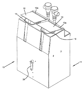
throughout the several views, there is generally disclosed at 10 a dispenser.
The dispenser 10 includes a housing 11. The housing 11 has two lids 12,
13 operatively connected to the housing 11 by suitable means such as a
hinges 13, 14a. The housing 11 encircles the dispenser 10. However, as
shown in Figure 2, the back and bottom have been removed for clarity.
The housing 11 has an inner cavity 11a in which two product holders 14, 15
are positioned. The product holders 14, 15 are for receiving a suitable solid
product such as a detergent, sanitizer or other suitable chemicals from
which it is desired to malce a use solution. Dispenser 10 is shown as having
two product holders 14, 15. However, it is understood that either a single
product holder or more product holders may also be incorporated in a
dispenser 10 that utilizes the present invention. The dispenser 10 has a
7
CA 02575766 2007-01-31
WO 2006/044678 PCT/US2005/037047
screen 16 that extends across the cavity 11a and is connected to the sides of
the housing 11. The product holders 14, 15 may be supported by the screen
16. The size and mesh opening of the screen 16 are dependent on the
chemical to be dispensed and the other factors, well known in the art.
Operatively positioned below each product holder 14, 15 is a conical
member 17. The conical member 17 is shown, in Figure 2, positioned
below the product holder 15. A similar conical member is positioned
underneath the product holder 14, but is obscured from view in Figure 2.
The conical member 17 forms a conical cavity. A manifold 18 is
operatively connected below the bottom of the conical member 17 by
means well known in the art. The conical member 17 sits in the cylindrical
opening or bore 18a and rests on the shelf 18b. The cylindrical opening
18a extends down to the bottom of the manifold 18, as viewed in Figure 6.
The end of the opening 18a forms the outlet for the use solution. The
conical member 17 also acts as a collection member for directing the use
solution to cylindrical opening 18a of the manifold 18. A block member 19
is suitably attached to the manifold 18 by means well known in the art such
as a screw 20. The block member 19 has three bores 19a, 19b, 19c that
extend through the block member 19. A passageway 18c is formed in the
manifold 18 and is in fluid communication with the bore 19a. The
passageway 18c has its other end in fluid communication with a nozzle 21.
An O-ring 23 is positioned between the block member 19 and manifold 18
around the bore 19a to provide for a liquid tight seal. A fitment 24, having
a first member 24a operatively connected to a second member 24b, is
8
CA 02575766 2007-01-31
WO 2006/044678 PCT/US2005/037047
positioned in the bore 19a. The fitment 24 is adapted and configured to be
connected to a conduit, as will be discussed hereafter. An 0-ring 25 is
positioned at the end of the fitment 24 inside of the bore 19a. A second
passageway 18d is formed in the manifold 18 and has one end in fluid
communication with the bore 19b and the other end opening into the
cylindrical opening 18a. An 0-ring 26 is positioned around the
passageway 18d and the bore 19b. A fitment 27, having a first member 27a
and a second member 27b, is positioned in one end of the bore 19b and is
positioned on an 0-ring 28. A third passageway 18e is formed in the
manifold 18 and is in fluid communication with the bore 19c. The second
passageway 18b opens into the cylindrical opening 18a. A fitment 29,
having a first member 29a and a second member 29b, is positioned on an
0-ring 30 in the bore 19c. An 0-ring 31 is positioned between the
manifold 18 and block member 19 proximate the bore.19c and passageway
18e. The third passageway 18e opens into the cylindrical opening 18a.
However, while the passageways 19d, 19e enter into the cylindrical
opening 18a, an insert 32 is positioned in the cylindrical opening 18a.
Three flow controls are utilized in the three passageways formed in the
manifold 18 and block 19. A first flow control 70 is positioned in an insert
71 and secured in the first passageway 18c. A second flow control 73 is
positioned in the second insert 74 and positioned in the second passageway
18d. Finally, the third flow contro175 is positioned in the second insert 76
which is positioned in turn in the third passageway 18e. An 0-ring 72 is
positioned behind the fitment 71. The flow controls 70, 73, 75 are flow
9
CA 02575766 2007-01-31
WO 2006/044678 PCT/US2005/037047
controls made of a suitable material such as EPM rubber and are flexible
and change in shape with respect to changes in pressure in the diluent. The
flow controls 70, 73, 75 control flow of the diluent independent of pressure
within a reasonable flow range and will have variable orifices 70a, 73a, 75a
that change in size dependent on the pressure of the diluent. Any suitable
flow controls may be utilized, such as those available from Vernay
Laboratories, Inc. The flow controls are referred to as dynamic flow
controls. The dynamic flow controls restrict their variable orifices based on
pressure, thereby providing a range of flow rates over a range of pressures
without the use of electronics to control the flow controls. The specific
flow controls that are utilized will be dependent upon the gallon per minute
flow rate that is desired. For instance, if a 0.3 gallon per minute flow rate
is
desired, a suitable part number such as VL3007-111 may be utilized. Other
flow controls would be used if different flow rates are required. As one
example, flow control 70 may be a 0.3 gallon per minute flow control, flow
control 73 and 2.0 gallon per minute flow control and the third flow control
75 a 3.5 gallon per minute flow control. This will be discussed more fully
hereinafter.
The insert 32, as shown in Figures 6 and 7, has a first section 32a
and a second section 32b. The second section 32b has an exit opening 32c
at its end.
The insert 32 is a water dampener and reduces turbulents that
contributes to foam generation. The first section 32a forms a housing that
receives the diluent from passageways 18d, 18e. The passageways 18d and
CA 02575766 2007-01-31
WO 2006/044678 PCT/US2005/037047
18e may enter from the side, as shown in the figures, or from other
directions, such as from the top. The first section 32a has a rectangular
opening that is sized and configured to fit around the passageways 18d, 18e
when the insert 32 is placed inside of the bore 18a. The passageway around
the insert 32 is defined by the area between the fins and the wall of the
cylindrical opening 18a. In this manner, the insert does not block the flow
of the use solution. The cylindrical opening 18a provides for the dispenser
outlet passageway and has a dispenser outlet at its end, wherein a suitable
conduit (not shown) will take the use solution and deliver it to an
appropriate end use. The first section 32a is enclosed and therefore the
diluent from passageways 18d, 18e enter into the first section 32a through
the rectangular opening 32d and exits through an opeining 32e that is in
fluid communication with the second section 32b. The second section 32b
includes a first conical section 32f operatively connected to a tubular
section 32g which is an exit conduit. Three fins 32h extend radially
outward from the first section 32a. The fins 32h form a friction fit with the
bore 18a and hold the insert 32 in position. The fins provide for a
passageway for the use solution that enters the top of the cylindrical
opening 18a. The use solution is able to go around the outside of the insert
32. Referring to Figure 8, the top portion of the insert 32 has been removed
for clarity when preparing this Figure, so that the nozzle 21 is visible.
The dispenser 10 has a main diluent inlet 33 that has an opening 33a
that is adapted and configured to receive an inlet line (not shown) that
carries the diluent, typically water. A handle 34 is used as a shut-off valve
11
CA 02575766 2007-01-31
WO 2006/044678 PCT/US2005/037047
to open and close the inlet opening 33a. The main inlet 33 has two exits
33b, only one of which is shown in Figure 2. A schematic of the flow is
shown in Figure 3. However, in the figures, for clarity, the conduit or
tubing has been replaced with lines having arrows. In Figure 3, sections of
the tubing or conduit is shown as illustrative of what the conduit may look
like. However, the insertion of the conduit into Figure 2 would obscure
several parts from view and accordingly has been replaced by the lines with
arrows. The exit 33b that is shown is in fluid communication, by suitable
means such as a conduit 35 to and inlet 36a of a vacuum breaker 36. The
other exit of the inlet 33c is in fluid communication by suitable means such
as a conduit 37 to an inlet 38a of a second vacuum breaker 38. The first
vacuum breaker 36 has an outlet 36b that is in fluid communication with a
manifold 39 by suitable means such as a conduit 40. It is understood that
the manifold 39 may take on any number of different forms, well known in
the art. The manifold 39 is for taking a single flow of diluent and dividing
it into two or more streams of diluent. The entrance opening 39a of the
manifold 39 is in fluid communication with three outlets 39a, 39b, 39c.
Outlet 39a is in fluid communication with a thermal valve 41 as will be
described more fully hereafter. The outlet 39a is in fluid communication by
suitable means such as a conduit 42. Outlet 39b is in fluid communication
with bore 19a by suitable means such as a conduit 43 and outlet 39c is in
fluid communication with the thermal valve 41 by suitable means such as a
conduit 44. Referring now, especially to Figures 4 and 5, there is shown a
thermal valve assembly 41. The thermal valve assembly 41 includes a
12
CA 02575766 2007-01-31
WO 2006/044678 PCT/US2005/037047
typical valve 45 that has an inlet 45a and an outlet 45b. A passageway 46
places the inlet 45a in fluid communication with the outlet 45b. A spring
47 is positioned inside of bore 48. The spring 47 has one end against the
valve 45 and another end against a cap 49. A rubber gasket 50 has a central
opening and is positioned around the exit 51 of the spool 52. A rod 53 is
positioned through the spool 52 and goes into the cap 49. A viewed in
Figures 4 and 5, movement to the left by the rod 53 will cause the cap 49 to
move off of the exit 51 and allowing water to pass from the inlet 45a to the
outlet 45b. It is understood that any suitable valve 45 may be utilized with
the thermal valve assembly 41. The spool 52 is operatively connected to
the valve 45 by screw threads 52a and has an 0-ring 54 positioned between
the valve 45 and the spoo152. A cylindrical housing 55 has a first end 55a
that is threaded and is adapted and configured to be operatively connected
to the valve 45 by threading on to mating grooves in the spool 52. The end
55 has an aperture through which the rod 53 is positioned. The cylindrical
housing 55 has a cavity 55b in which a thermal motor 56 is positioned. The
cavity 55a has a distal end 55c that is sized and configured to support a
first
end 56a of the thermal motor 56. The cylindrical housing has an inlet
opening 55d and an outlet opening 55e to allow water to pass therethrough.
The thermal motor 56 may be any suitable thermal sensitive member that
expands or changes in length as its temperature changes. One suitable
example is Model No. MMV by Watts Regulator Company, Laurence,
Massachusetts. The cap 57 includes a generally cylindrical member 57a
operatively connected to a disc member 57b. The cylindrical member 57a
13
CA 02575766 2007-01-31
WO 2006/044678 PCT/US2005/037047
is sized and configured to fit inside of the cavity 55a. An 0-ring 58 is
positioned between the cylindrical housing 55 and the cap 57 to provide a
water-tight seal. The cap 57 is secured to the housing 55 by suitable means
such as screws 59. An adjustment element 60 is operatively corinected to
the cap 57. The element 60 has a cylindrical body that is adapted and
configured to fit inside of the cylindrical member 57a of the cap 57. The
adjustment element 60 has a cylindrical element 60a that has a threaded
section 60b that matches with corresponding grooves formed in the cap 57.
The cylindrical member 60a is sealed against the cap 57 by an O-ring 61.
As can be seen in Figure 5, the cylindrical member 60a is sized and
configured to receive the thermal motor 56. A ball bearing or similar
device 61 is positioned in the inner cavity 60b of the cylindrical member
60a. The adjustment element 60 has an end 60b that is secured to a knob
62 by suitable means such as a screw 63. It can therefore be seen that as a
knob 62 is rotated, the adjustment element 60 will move in and cut of the
cap 57 thereby moving the thermal motor 56 closer to or further away from
the end of the rod 53 and thereby changing the temperature at which the rod
53 will open the valve 45. It is also understood that another way of
adjusting the valve assembly 41 is to change the length of rod 53.
An adapter 80 is secured to the bottom of the manifold 18. The
adapter 80 has a central bore that is in alignment with the cylindrical
opening 18a and provides for a mechanism to collect the use solution and
guide it into a suitable conduit (not shown) that is connected on the end of
the adapter 80. The conduit that would be connected to the adapter 80
14
CA 02575766 2007-01-31
WO 2006/044678 PCT/US2005/037047
would remove not only the use solution, but also the diluent exiting the
insert 32.
The product in the holder 14 does not utilize a thermal valve
assembly and therefore has a slightly different construction with respect to
the flow of the diluent or water. The water flows from the outlet 38b of the
second vacuum breaker 38 to a manifold 65. The manifold 65 is similar in
construction to the manifold 39. The manifold 65 is in fluid
communication with the outlet 38b of the second vacuum breaker by
suitable means such as a conduit 64. The manifold 65 has an inlet 65a that
is in fluid communication with three outlets 65a, 65b, 65c. However, since
a thermal valve assembly is not utilized, only two outlet ports of the
manifold 65 are utilized. The third outlet port 65c is plugged, with a
suitable plug (not shown). Similarly, a manifold 18 and block 19 are
utilized, but the third passageway 18e is not utilized. The outlet 65b is in
fluid communication by a suitable conduit 66 with the fitment 34 of block
19. The outlet 65c is in fluid communication with a suitable conduit 67
with fitment 27. Again, suitable flow controls 70, 73 are utilized in the
block 18 used with the dispenser associated with the second product holder
15.
In operation, the dispenser 10 delivers use solutions from solids
through the use of flow controls for the diluent. The diluent is split into
either two or three streams depending on whether or not the product being
dispensed is temperature sensitive for erosion. When the use solution is
desired, the handle 34 is rotated thereby allowing diluent to pass through
CA 02575766 2007-01-31
WO 2006/044678 PCT/US2005/037047
the main inlet 33. It is understood that the present invention can be utilized
with one or more different products, two of which are shown in the
drawings. Further, it is understood that the present invention may be
utilized with or without the temperature control feature of the thermal valve
assembly 41. The product being dispensed from holder 15 will be
described with respect to use of the thermal valve 41 and the product to be
dispensed from product holder 14 will be described with respect to not
using the thermal valve 41.
The water flowing into the main inlet 33 will be diverted to both the
first vacuum breaker 36 and second vacuum breaker 38, although it is
understood that only one may be utilized with the present invention. From
the first vacuum breaker 36, the water passes to the first manifold 39a
through the inlet 39a and exits the three outlets 39a, 39b, 39c. The water
exiting outlet 39b passes through the second manifold through bore 19a and
passageway 18c. There, the water will exit the nozzle 21 and form an
appropriate spray pattern and erode the product (not shown) held in the
product holder 15 and a use solution will be formed. The use solution will
fall down into the conical member 17 and enter the cylindrical opening 18a
in the manifold 18. The use solution will pass around the insert 32 in the
channels created by the fins and exit the outlet of the cylindrical opening
18a between the adapter 80 and the second section 32b of the insert 32.
The diluent exiting outlet 39a will enter the thermal valve 41 and pass
through the opening 55d and out of the opening 55e into the bore 19b. It
will then exit the second passageway 18d and empty into the first section
16
CA 02575766 2007-01-31
WO 2006/044678 PCT/US2005/037047
32a of the insert 32. The diluent exiting the outlet 39c will pass, via
conduit 44, to the inlet 45a of the valve 45. However, if the temperature of
the diluent is below a piredetermined value, the valve 45 will be closed.
The predetermined value will change dependent on the product and
concentration needed. If the diluent or water increases in temperature, the
thermal motor 56 is exposed to the diluent as it is passing through the
openings 55d, 55e. As the temperature increases, the thermal motor 56
expands in size and opens the valve 45, thereby allowing more water to
enter into the first section 32a of the insert 32 through the bore 19c and
third passageway 18e. This additional diluent reduces the concentration of
the use solution that would increase as the temperature increases.
Flow through all of the passageways 18d, 18e, 18f is controlled by
the flow controls 70, 73, 75. The flow controls 70, 73, 75 are seated
dynamic flow control devices that control the flow of the water, as will be
described more fully hereafter, to provide for a controlled reasonable flow
range of the diluent.
The diluent that enters the insert 32 does not mix immediately with
the use solution. The use solution, as it is passing outside the insert 32, is
generally in a downward direction. Similarly, the diluent in the insert 32
will be redirected so that it is not at an angle to the use solution, but will
again be flowing generally downward and parallel to the use solution.
Therefore, when the use solution mixes with the diluent from the insert 32,
the diluent and use solution are moving generally in the same direction,
thereby minimizing shear forces and thereby reducing foam.
17
CA 02575766 2007-01-31
WO 2006/044678 PCT/US2005/037047
The product to be dispensed from product holder 14 does not erode
at substantially different rates, dependent upon the temperature of the
diluent. Accordingly, it is not necessary that a thermal valve 41 is utilized.
Instead, only flow through the first passageway 18c and second passageway
18d are utilized and is the same as described with respect to the product
dispensed from product holder 15 and will not be reiterated. The flow
control members 70, 73 are utilized to again control the volume of diluent
as will be described more fully hereafter. Again, the diluent through the
second passageway 18d enters the insert 32 to reduce foaming.
The present invention is able to provide a dispenser that is able to
provide a use solution at a desired concentration without the use of
electronics or controls. The use of the dynamic flow control in the
passageway provides for flow, within a range, independent of pressure
within the system over a reasonable flow range such as from 30-100 psi.
Figure 9 is a chart of the range of the flow rate in gallons per minute verses
pressure in pounds per square inch of a dispenser that utilizes a .33 gallon
per minute flow control and a 3.0 gallon per minute flow control with a .28
nozzle. The bottom line shows that the dispensing rate of the .33 flow
control is relatively constant over the measured range of from 15 to 90 psi.
Similarly, the flow rate of the 3.0 gallon per minute flow control is
relatively constant between the pressures of 15 and 90, and especially more
consistent within the range of 30 to 90 psi. At the rate of 30 psi for both
flow controls, the flow rate is at or above the desired rate. Applicant has
18
CA 02575766 2007-01-31
WO 2006/044678 PCT/US2005/037047
also found that this relationship extends to 100 psi, even though not shown
in the chart.
Figure 10 is a chart showing use of the present invention for
dispensing quaternary salt from a detergent having 40 percent quaternary
salt. The chart is representative of a 20-gallon fill. As can be seen, the
line
for "without temperature compensation" indicates a dispenser that does not
have the thermal valve of the present invention, wherein the lower line
utilizes the thermal valve of the present invention. As shown in Figure 10,
the thermal valve assembly 41 is set to open at 120 degrees. Therefore,
since the thermal valve would open at 120 degrees, additional water would
be dispensed, thereby decreasing the time to dispense 20 gallons and
thereby deleting the total number of grams of product dispensed for a 20-
gallon fill.
Referring now to Figures 11 and 12, it can be seen how the present
invention is able to keep the concentration of the use solution within a
specified range for a range of temperatures and water pressures. Figure 11
utilizes a dispenser that has a flow contro170 of 0.33 gallons per minute, a
flow control 73 of 3.5 gallons per minute and a flow control 75 of 2.0
gallons per minute. The nozzle 21 is rated at 0.28 gallons per minute. This
is also for a quaternary salt where a desired concentration is between 150-
300 parts per million. The thermal valve 41 is set to open at 120 degrees.
It can be seen that there are certain areas that are not in the desired range
of
150-300 parts per million as represented by the lightest shade and the
darkest shade. With the present invention, it is then able to be adjusted by
19
CA 02575766 2007-01-31
WO 2006/044678 PCT/US2005/037047
simply changing one or more of the variables. For instance, it would be
possible to increase the flow rate through the thermal bypass 41, thereby
bringing down the concentration at the higher temperatures. Alternately,
the amount of product being dissolved may be controlled by reducing the
flow through the nozzle 21. Figure 12 represents a dispenser, similar to
Figure 11, expect flow contro170 was lowered to a 0.3 gallons per minute.
Then, the parts per million reading are represented by the numbers in the
chart. It can be seen that all of the numbers are within the desired range of
150-300 parts per million throughout the range of 30-100 psi and a
temperature range of from 90-140 degrees. It is recognized that two of the
readings are at 310, slightly out of the desired range. However, this is well
within experimental error in testing. One additional change with respect to
Figure 12 is that the thermal bypass was set to be activated at 117 degrees
rather 120 degrees.
It can therefore be seen that the present invention is very useful in
designing a dispenser that utilizes dynamic flow controls that does not rely
on electronics to provide for a desired concentration of a use solution.
While the examples described so far have been with respect to a quaternary
salt, it is understood that other formulations such as all-purpose cleaners,
acid floor cleaners, alkaline floor cleaners and third sink sanitizers as well
as other formulas may be utilized. In dispensing the desired concentration
from a product, it is understood that it would be dependent upon the
product being dispensed and the nozzle. Accordingly, a nozzle 21 is
selected that provides for an appropriate spray on the area of the product
CA 02575766 2007-01-31
WO 2006/044678 PCT/US2005/037047
being dispensed. The spray pattern should typically cover the entire block.
The flow control 70 for the nozzle 21 is typically sized slightly larger then
that of the capacity of the nozzle. For instance, if a 0.28 flow rate nozzle
is
desired, a 0.30 or 0.33 flow control is provided. The nozzles are typically
rated at the flow rate at 10 psi. Typically, the pressure will effect the
force
on which the water is impinged on the product and the flow rate will
determine the amount of product dissolved. One can easily measure the
amount of product that is dissolved over a targeted time. Then, it is simply
necessary to supply an additional amount of diluent through the flow
contro173 to provide the desired concentration. Alternately, if the product
being dispensed is temperature sensitive with respect to the diluent, the
thermal valve 41 may be utilized and flow is provided through the flow
contro175.
The above specification, examples and data provide a complete
description of the manufacture and use of the composition of the invention.
Since many embodiments of the invention can be made without departing
from the spirit and scope of the invention, the invention resides in the
claims hereinafter appended.
21