Note: Descriptions are shown in the official language in which they were submitted.
CA 02576061 2007-02-05
WO 2006/017603 PCT/US2005/027627
1
TAMPER-INDICATING PRINTABLE SHEET FOR SECURING DOCUMENTS
OF VALUE AND METHODS OF MAKING THE SAME
TECHNICAL FIELD
The present invention relates to a printable sheet for securing documents of
value
that is capable of indicating tampering. The present invention relates more
particularly to
a printable sheet including a retroreflective layer comprising a plurality of
microbeads
partially embedded in an inkjet receptive beadbond layer and a reflector layer
between at
least one of the microbeads and the inkjet receptive beadbond layer. The
present invention
also relates to a method of making a tamper-indicating printable sheet.
BACKGROUND OF THE INVENTION
Documents of value such as passports, identification cards, entry passes,
ownership
certificates, financial instruments, and the like, are often assigned to a
particular person by
personalization data. Personalization data, often present as printed images,
can include
photographs, signatures, fingerprints, personal alphanumeric information, and
barcodes,
and allows human or electronic verification that the person presenting the
document for
inspection is the person to whom the document is assigned. There is widespread
concern
that forgery techniques can be used to alter the personalization data on such
a document,
thus allowing non-authorized people to pass the inspection step and use the
document in a
fraudulent manner.
A number of security features have been developed to help authenticate the
document of value, thus assisting in preventing counterfeiters from altering,
duplicating or
simulating a document of value. Some of these security features may include
overt
security features or covert security features. Overt security features are
features that are
easily viewable to the unaided eye, such features may include holograms and
other
diffractive optically variable images, embossed images, and color-shifting
films. In
contrast, covert security features include images only visible under certain
conditions,
such as inspection under light of a certain wavelength, polarized light, or
retroreflected
light. One example of a laminate that includes both overt and covert security
features is
CA 02576061 2007-02-05
WO 2006/017603 PCT/US2005/027627
2
3MTM ConfirmTM Security Laminate, which is commercially available from 3M
Company
based in St. Paul, Minnesota. This security laminate may be used with
documents of
value, such as identification cards, badges and driver licenses, and assists
in providing
identification, authentication and to help protect against counterfeiting,
alteration,
duplication, and simulation. Another example of a laminate that includes both
overt and
covert security features is illustrated in U.S. Pat. Publication No.
2003/0170425 Al
"Security Laminate," (Mann et al.) Examples of some other devices are taught
in U.S.
Pat. Nos. 3,801,183 and 4,688,894.
Although the commercial success of available security features has been
impressive, as the capabilities of counterfeiters continue to evolve, it is
desirable to further
improve the ability to indicate that a security feature has been tampered with
or somehow
compromised to help protect against counterfeiting, alteration, duplication,
and simulation.
SUMMARY OF THE INVENTION
One aspect of the present invention provides a tamper-indicating printable
sheet.
The tamper-indicating printable sheet comprises: a retroreflective layer
comprising a
plurality of microbeads partially embedded in an inkjet receptive beadbond
layer; and a
reflector layer between at least one of the microbeads and the inkjet
receptive beadbond
layer. In one preferred embodiment of the above tamper-indicating printable
sheet, the
tamper-indicating printable sheet further comprises a covert indicia between
the reflector
layer and the microbead. In another aspect of this embodiment, the covert
image includes
a printed symbol, word, logo, or any combination thereof.
In another preferred embodiment of the above tamper-indicating printable
sheet,
the tamper-indicating printable sheet further comprises an image printed on
the inkjet
receptive beadbond layer. In another aspect of this embodiment, after a
portion of the
printed image is removed from the inkjet receptive beadbond layer, a plurality
of
retroreflective microbeads detach from the portion of the retroreflective
layer to indicate
tampering. In yet another aspect of this embodiment, the portion of the
printed image is
removed by image removing liquids. In another aspect of this embodiment, the
printed
image comprises inkjet ink. In yet another aspect of this embodiment, the
printed image
includes a printed image of a human face, signature, fingerprint, alphanumeric
information, a barcode, or any combination thereof.
CA 02576061 2007-02-05
WO 2006/017603 PCT/US2005/027627
3
In another preferred embodiment of the above tamper-indicating printable
sheet,
the tamper-indicating printable sheet further comprises a layer of adhesive
attached to the
inkjet receptive beadbond layer. In another aspect of this embodiment, the
tamper-
indicating printable sheet further comprises a liner attached to the layer of
adhesive. In
another aspect of this embodiment, the tamper-indicating printable sheet
further comprises
a security indicia viewable under retroreflective light conditions. In another
aspect of this
embodiment, the tamper-indicating printable sheet further comprises an overt
indicia on
the inkjet receptive beadbond layer. In another aspect of this embodiment, the
overt image
includes a printed image of a human face, signature, fingerprint, alphanumeric
information, a barcode, or any combination thereof.
In another preferred embodiment of the above tamper-indicating printable
sheet, a
plurality of microbeads detach from the inkjet receptive beadbond layer after
image
removing liquids are applied to the inkjet receptive layer and tampering is
thereby
indicated.
Another aspect of the present invention provides a security document
comprising
in combination: an embodiment of the tamper-indicating printable sheet; and a
document
of value, where the printable sheet is inserted or attached to the document of
value. In
another aspect of this embodiment, the document of value is a passport,
identification
card, financial document, entry pass, ownership certificate, a visa, birth
certificate,
resident authorization or any other security or identification-related
document.
Another aspect of the present invention provides an alternative tamper-
indicating
printable sheet. This tamper-indicating printable sheet comprises: a
retroreflective layer
comprising a plurality of microbeads partially embedded in an inkjet receptive
beadbond
layer; a reflector layer between at least one of the microbeads and the inkjet
receptive
beadbond layer; and a printed image on the inkjet receptive beadbond layer;
where after a
portion of the printed image is removed from the inkjet receptive beadbond
layer, a
plurality of retroreflective microbeads detach from the portion of the inkjet
receptive
beadbond layer to indicate tampering. In another aspect of this embodiment,
the tamper-
indicating printable sheet further comprises a covert indicia between the
reflector layer
and the microbead. In yet another aspect of this embodiment, the covert image
includes a
printed symbol, word, logo, or any combination thereof. In another aspect of
this
embodiment, the portion of the printed image is removed by image removing
liquids.
CA 02576061 2007-02-05
WO 2006/017603 PCT/US2005/027627
4
In another preferred embodiment of the above tamper-indicating printable
sheet,
the printed image comprises inkjet ink. In another preferred embodiment of the
above
tamper-indicating printable sheet, the printed image includes a printed image
of a human
face, signature, fingerprint, alphanumeric information, a barcode, or any
combination
thereof. In yet another preferred embodiment of the above tamper-indicating
printable
sheet, the tamper-indicating printable sheet further comprises a layer of
adhesive attached
to the inkjet beadbond layer. In another aspect of this embodiment, the tamper-
indicating
printable sheet further comprises a liner attached to the layer of adhesive.
In yet another preferred embodiment of the above tamper-indicating printable
sheet, the tamper-indicating printable sheet further comprises a security
indicia viewable
under retroreflective light. In another preferred embodiment of the above
tamper-
indicating printable sheet, the tamper-indicating printable sheet further
comprises an overt
indicia on the inkjet receptive beadbond layer. In another aspect of this
embodiment, the
overt image includes a printed image of a human face, signature, fingerprint,
alphanumeric
information, a barcode, or any combination thereof. In yet another preferred
embodiment
of the above tamper-indicating printable sheet, a plurality of microbeads
detach from the
inkjet receptive beadbond layer after image removing liquids are applied to
the inkjet
receptive beadbond layer and tampering is thereby indicated.
Another aspect of the present invention provides a security document
comprising
in combination: an embodiment of the tamper-indicating printable sheet; and a
document
of value, where the printable sheet is inserted or attached to the document of
value. In
another aspect of this embodiment, the document of value is a passport,
identification
card, financial document, entry pass, ownership certificate, a visa, birth
certificate,
resident authorization or any other security or identification-related
document.
Another aspect of the present invention provided yet another alternative
tamper-
indicating printable sheet. This tamper-indicating printable sheet, comprises:
a
retroreflective layer comprising a plurality of microbeads partially embedded
in an inkjet
receptive beadbond layer, where the inkjet receptive beadbond layer is
formulated such
that it indicates tampering; and a reflector layer between at least one of the
microbeads and
the inkjet receptive beadbond layer.
In another preferred embodiment of the above tamper-indicating printable
sheet,
the tamper-indicating printable sheet, further comprises a covert indicia
between the
CA 02576061 2007-02-05
WO 2006/017603 PCT/US2005/027627
reflector layer and the microbead. In another preferred embodiment of the
above tamper-
indicating printable sheet, the covert image includes a symbol, word, logo, or
any
combination thereof. In another aspect of this embodiment, the tamper-
indicating
printable sheet further comprises an image printed on the inkjet receptive
beadbond layer.
5 In another aspect of this embodiment, after a portion of the printed image
is removed from
the inkjet receptive beadbond layer, a plurality of retroreflective microbeads
detach from
the portion of the retroreflective layer to indicate tampering. In yet another
aspect of this
embodiment, the printed image comprises inkjet ink. In another aspect of this
embodiment, the printed image includes a printed image of a human face,
signature,
fingerprint, alphanumeric information, a barcode, or any combination thereof.
In another preferred embodiment of the above tamper-indicating printable
sheet,
the tamper-indicating printable sheet further comprises a layer of adhesive
attached to the
inkjet receptive beadbond layer. In another aspect of this embodiment, the
tamper-
indicating printable sheet further comprising a liner attached to the layer of
adhesive. In
another preferred embodiment of the above tamper-indicating printable sheet,
the tamper-
indicating printable sheet further comprising a security indicia viewable
under
retroreflective light. In another preferred embodiment of the above tamper-
indicating
printable sheet, the tamper-indicating printable sheet, further comprising an
overt indicia
on the inkjet receptive beadbond layer. In another aspect of this embodiment,
the overt
image includes a printed image of a human face, signature, fingerprint,
alphanumeric
information, a barcode, or any combination thereof.
In another preferred embodiment of the above tamper-indicating printable
sheet, a
plurality of microbeads detach from the inkjet receptive beadbond layer after
image
removing liquids are applied to the inkjet receptive beadbond layer and
tampering is
thereby indicated.
Another aspect of the present invention provides a security document
comprising
in combination: an embodiment of the tamper-indicating printable sheet; and a
document
of value, where the printable sheet is inserted or attached to the document of
value. In
another aspect of this embodiment, the document of value is a passport,
identification
card, financial document, entry pass, ownership certificate, a visa, birth
certificate,
resident authorization or any other security or identification-related
document.
CA 02576061 2007-02-05
WO 2006/017603 PCT/US2005/027627
6
Another aspect of the present invention provides a method of making a tamper-
indicating printable sheet. This method comprises the steps of: providing a
liner and a
plurality of microbeads; partially embedding the plurality of microbeads into
the liner;
coating a reflector layer on the plurality of microbeads; and coating an
inkjet receptive
beadbond layer on the reflector layer and plurality of microbeads. In another
preferred
embodiment of the above method, the method, further includes the step of:
printing an
image on the inkjet receptive beadbond layer. In another preferred embodiment
of the
above method, the method further including the steps of: after the partially
embedding
step, printing a covert indicia on the plurality of microbeads; and where the
first coating
step includes coating a reflector layer on the covert indicia and plurality of
microbeads. In
another aspect of this embodiment, the method further including the steps of:
removing a
portion of the printed image on the retroreflective layer from the inkjet
receptive beadbond
layer; and detaching a plurality of retroreflective microbeads from the
portion of the inkjet
receptive beadbond layer to thereby indicate tampering. In another aspect of
this
embodiment, the printed image is removed from the inkjet receptive beadbond
layer image
removing liquids. In another preferred embodiment of the above method, the
method
further includes the step of: printing an overt indicia on the inkjet
receptive beadbond
layer. In another aspect of this embodiment, the method further including the
step of:
coating a layer of adhesive on the retroreflective layer.
In another preferred embodiment of the above method, the method further
includes the
step of: applying the adhesive to a substrate; and stripping the liner from
the plurality of
microbeads such that the plurality of microbeads is partially embedded in the
inkjet
beadbond layer. In another preferred embodiment of the above method, the
method
further includes the step of: inserting or attaching the tamper-indicating
printable sheet to a
document of value. In another aspect of this embodiment, the document of value
is a
passport, identification card, financial document, entry pass, ownership
certificate, a visa,
birth certificate, resident authorization or any other security or
identification related
document.
Certain terms are used in the description and the claims that, while for the
most
part are well known, may require some explanation. The term "retroreflective"
as used
herein refers to the attribute of reflecting an incident light ray in a
direction antiparallel to
CA 02576061 2007-02-05
WO 2006/017603 PCT/US2005/027627
7
its incident direction, or nearly so, such that it returns to the light source
or the immediate
vicinity thereof.
As used herein, the term "normal lighting conditions" refers to the presence
of
ambient light that is substantially diffused, as with light typically used to
light a room.
The term "retroreflected light conditions" refers to ambient light that is
substantially
collimated, such as light cast by the headlight of an automobile or by a
flashlight, and
returns to the light source or the immediate vicinity thereof. The term
"unaided eye"
means normal (or corrected to normal) human vision not enhanced by, for
example,
magnification.
BRIEF DESCRIPTION OF THE DRAWINGS
The present invention will be further explained with reference to the appended
Figures, wherein like structure is referred to by like numerals throughout the
several
views, and wherein:
Figure 1 illustrates a cross-sectional view of one embodiment of the tamper-
indicating printable sheet of the present invention;
Figure 2 illustrates a cross-sectional view of another embodiment of the
tamper-
indicating printable sheet of the present invention;
Figure 3 illustrates the tamper-indicating printable sheet of Figure 1, where
the
detachment of the microbeads indicates tampering;
Figure 4 is a digitally recorded micrograph of a prior art security laminate
with a
portion of the printed image removed , as viewed under normal lighting
conditions;
Figure 5 is a magnified view of the prior art security laminate of Figure 4
under
retroreflective lighting conditions;
Figure 6 is digitally recorded micrograph of the tamper-indicating printable
sheet
of the present invention with a portion of the printed image removed under
normal lighting
conditions;
Figure 7 is a magnified view of the tamper-indicating printable sheet of
Figure 6
under retroreflective lighting conditions; and
CA 02576061 2007-02-05
WO 2006/017603 PCT/US2005/027627
8
Figure 8 illustrates a cross-sectional view of another embodiment of the
tamper-
indicating printable sheet of the present invention.
DETAILED DESCRIPTION OF THE INVENTION
Many countries have passport offices, which will issue passport booklets to
applicants. Typically, a passport includes multiple pages and one of the pages
within the
passport booklet is printed with personalization information about the
specific applicant,
such as their picture, full legal name, nationality, date of birth, etc., and
certain passport
identifying information, such as a machine-readable zone or barcode. After the
information is printed, some passport offices will laminate a security film
over the printed
information to assist in identifying and authenticating the passport. This
security film may
further help to indicate that the information may have been tampered with at a
later date.
This lamination process usually requires special equipment using heat and
pressure to
laminate the security film to the printed passport page. One example of such a
security
film is commercially available from 3M Company based in St. Paul, Minnesota as
3MTM
ConfirmTM Security Laminate. This security film includes covert images that
are visible
when viewed with a 3MTM Viewer, which includes a focused light, which assists
in
identifying and authenticating a valid passport. In addition, if a
counterfeiter tries to
change the printed information under the laminated security film, the 3MTM
ConfirmTM
security laminate will necessarily be peeled apart to get access to the
printed information
which results in destroying the film and disrupting the printed information
and possibly
the covert image, as well, which indicates that tampering has occurred.
Typically, normal passports are issued through a country's central passport
processing locations. To request a normal passport, a person will fill out an
application
and submit their personal information, including a current photograph or a
picture taken of
them at the processing location. The passport office will then process the
application and
make a determination whether or not to issue a passport to the applicant based
on a variety
of factors. This process from application to issuance of the passport can
typically take a
long time, such as up to four weeks or longer.
However, the passport office may receive requests for emergency or temporary
passports by applicants, where the applicant does not have time to wait four
weeks or
CA 02576061 2007-02-05
WO 2006/017603 PCT/US2005/027627
9
longer to receive the passport. For example, the applicant may have a sick
relative in
another country, or the applicant may have lost their passport while visiting
the country
and now needs a new passport to leave the country and return home. Therefore,
there is a
need to be able to issue these emergency passports very quickly, but yet still
provide the
security features necessary, such as providing proper identification,
authentication, and to
indicate whether or not the passport has been tampered with at a later date.
The printable sheet of the present invention may be used to issue emergency or
temporary passports to applicants because it may be easily printed and adhered
to one of
the pages in the emergency or temporary passport booklet by an adhesive, such
as a
pressure-sensitive adhesive. Thus, the printable sheet does not require the
special
equipment to laminate it to the passport booklet using heat and pressure. In
addition, the
printable sheet includes both overt and covert security features (described in
more detail
below), which assist in identifying and authenticating the passport as a valid
passport.
Lastly, the printable sheet is constructed so as to clearly indicate if the
passport has been
tampered with. In other words, if someone has removed the printed information
on the
sheet and replaced it with new printed information, such as a new name or
picture, to
create a fake passport, the tamper-indicating sheet of the present invention
reveals to an
inspector that the passport has been tampered with (described in more detail
below), and
the inspector may then take appropriate action, which may include stopping the
person
from either entering or leaving the country. It is possible that the tamper-
indicating,
printable sheet 10 of the present invention may also be used for issuing
normal passports
in the future or for other documents of value.
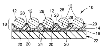
One embodiment of the tamper-indicating, printable sheet 10 of the present
invention is illustrated in Figure 1. The printable sheet 10 includes a
plurality of
retroreflective glass microbeads 12, preferably with each having a reflector
layer 20,
partially embedded in and protruding from an inkjet receptive beadbond layer
14.
Together, the retroreflective microbeads 12, reflector layers 20 and inkjet
receptive
beadbond 14 form a retroreflective layer 18. The microbeads 12 may be glass.
In one
embodiment, the microbeads 12 may range in size of from about 10 to about 200
micrometers. In another embodiment, the glass beads range in size from about
25
micrometers to about 75 micrometers. Such glass microbeads 12 typically have a
refractive index of at least about 1.8. Typically, the microbeads 12 of the
retroreflective
CA 02576061 2007-02-05
WO 2006/017603 PCT/US2005/027627
layer 18 are about hemispherically embedded into the inkjet receptive beadbond
layer 14.
However, the amount of the microbeads 12 embedded into the inkjet receptive
beadbond
layer 14 may vary from about 25 to about 75 % of the microbead diameter. The
reflector
layer 20 is preferably a transparent, high refractive index material. Examples
of useful
5 reflector layer materials include bismuth trioxide, zinc sulfide, titanium
dioxide, zirconium
oxide, and a stack of zinc sulfide/Na3A1F6. One example of a suitable
reflector layer 20 is
a transparent, high refractive index material as described in U.S. Patent No.
3,801,183,
which is hereby incorporated by reference.
The inkjet receptive beadbond layer 14 serves at least three purposes. First,
inkjet
10 receptive beadbond layer 14 is used to accept images or other information
in a discernable
or readable form. The ink 28 in the inkjet receptive beadbond layer 14 forms
this image
and other information. In one embodiment, an image 28 or other information is
inkjet
printed onto the exposed bead side of printable sheet 10, with the majority of
the printed
ink retained in the inkjet receptive layer 4. The printable sheets 10 may be
imaged using
water-based inks, solvent-based inks, and ultra violet light curable inks.
Preferably, the
printable sheets 10 may be imaged using an inkjet printer and water-based
inks. The inks
may utilize pigment or dye- based colorants. Second, inkjet receptive beadbond
layer 14
securely holds the microbeads 12 in place. Lastly, and quite unexpectedly, the
inkjet
receptive beadbond layer clearly indicates if the printable sheet has been
tampered with
after the passport office issued the passport. Specifically, if the printed
image 28 is
removed by image removing liquids, such as solvents, the printed sheet 10
indicates such
tampering by detachment or dislodgement of the microbeads 12 from inkjet
receptive
beadbond layer 14, as illustrated in Figure 3. Detachment of the microbeads 12
results in
a loss of retroreflectivity displayed by the retroreflective layer 18 in areas
in which
microbeads are detached and which appear as black areas 60 under
retroreflective lighting
conditions, which are clearly visible under retroreflective lighting
conditions, as illustrated
in Figure 7.
Preferably, the inkjet receptive beadbond layer 14 is water and abrasion
resistant.
Preferably, the inkjet receptive beadbond layer 14 is transparent. In another
embodiment,
the inkjet receptive beadbond layer may include an organosilane. Examples of
suitable
organosilanes include amino functional silanes (for example, Silquest A-1100,
Silquest
CA 02576061 2007-02-05
WO 2006/017603 PCT/US2005/027627
11
A-1120, or Silquest A-2120 from GE Silicones, Wilton, CT; or Dynasylan
CA0742 or
Dynasylan CM8620 from Huls America Inc., Piscataway, NJ), epoxy functional
silanes
(for example, Silquest A-186 or Silquest A-187 from GE Silicones, Wilton,
CT), and
sulfur functional silanes (for example, Silquest A-189 from GE Silicones,
Wilton, CT).
Preferred amino functional silanes include primary amino functional methoxy or
ethoxy
silanes such as Silquest A-1100 or Silquest A-1120. Preferred epoxy
functional
methoxy or ethoxy silanes include silanes such as Silquest A-186 or Silquest
A-187.
Useful inkjet receptive beadbond layers 14 include vinylpyrrolidone
homopolymers and copolymers and substituted derivatives thereof; vinyl acetate
copolymers, for example, copolymers of vinylpyrrolidone and vinyl acetate;
polyvinyl
alcohol; gelatins and modified gelatins; and the like as disclosed in U.S.
Patent Nos.
5,766,398; 4,775,594; 5,126,195; 5,198,306. Such materials may optionally also
include
inorganic materials such as alumina and/or silica particles.
In one embodiment, the inkjet receptive beadbond layer 14 comprises
polyvinylpyridine and may further include a crosslinker and/or a mordant.
Polyvinylpyridines, when at least partially neutralized with an appropriate
acid, are water-
soluble polymers that can be crosslinked. An exemplary polyvinylpyridine is
poly(4-
vinylpyridine). The inkjet receptive beadbond layer 14 may contain from
greater than 15
to about 100 dry weight percent polyvinylpyridine. In one embodiment, an
inkjet
receptive beadbond layer 14 of the invention contains at least greater than 15
weight
percent polyvinylpyridine on a dry basis. In other embodiments, the inkjet
receptive
beadbond layer 14 contains at least 20, at least 25, at least 30, or at least
35 weight percent
polyvinylpyridine. In other embodiments, the inkjet receptive beadbond layer
14 contains
from about 20 to 100, about 30 to 100, about 40 to 100, about 45 to 100, or
about 45 to 85
weight percent polyvinylpyridine on a dry basis and any whole or fractional
amount
between 20 and 100 weight percent.
The inkjet receptive beadbond layer 14 may contain one or more crosslinkers.
The
crosslinker provides a durable ink receptor by crosslinking the
polyvinylpyridine. Useful
crosslinkers include, but are not limited to, polyfunctional aziridine
compounds (for
example, XAMA-2 and XAMA-7, available from Sybron Chemicals, Birmingham, NJ),
polyfunctional epoxy compounds (for example, HELOXY Modifier 48, available
from
Resolution Performance Products, Houston, TX, or CR-5L, available from Esprix
Digital
CA 02576061 2007-02-05
WO 2006/017603 PCT/US2005/027627
12
Imaging Technologies, Sarasota, FL), polyfunctional isopropyloxazoline
compounds (for
example, EPOCROS WS-500, available from Esprix Digital Imaging Technologies,
Sarasota, FL), and epoxy functional methoxy silane compounds (for example, Z-
6040
SILANE, available from Dow Corning, Midland, MI).
The inkjet receptive beadbond layer 14 may contain an effective amount of
crossslinker to crosslink the polyvinylpyridine so to form a durable and
waterfast receptor.
The number of crosslinking sites per unit mass of crosslinker typically
characterizes the
effectiveness of a particular crosslinker. The number of crosslinking sites
(also sometimes
referred to as "equivalents") refers to the maximum number of bonds that an
amount of
crosslinker is theoretically able to form with a material to be crosslinked.
An equivalent
weight refers to the number of grams of crosslinker that contains 1 mole of
equivalents or
crosslinking sites.
Inkjet receptive beadbond layer 14 may contain from about 0.006 to about 1.5
millimoles crosslinking sites, from about 0.03 to about 0.6 millimoles
crosslinking sites, or
from about 0.03 to about 0.3 millimoles crosslinking sites per gram of
polyvinylpyridine.
The inkjet receptive beadbond layer 14 comprising polyvinylpyridine may
contain
one or more mordants. A "mordant" as used herein is a material that forms a
bond or
interaction with dyestuffs in inks. A mordant is used to fix the ink dyestuffs
so to provide
increased durability to images, particularly water resistance. Exemplary
mordants are
those materials or compounds that contain cationic moieties, for example,
quaternary
amino groups. Useful mordants include, but are not limited to, FREETEX 685 (a
polyquaternary amine, available from Noveon, Inc., Cleveland, OH), DYEFIX 3152
(a
ammonium chloride-cyanoguanidine-formaldehyde copolymer, available from Bayer,
Pittsburgh, PA), GLASCOL F207 (2-Propen-l-aminium, N,N-dimethyl-N-2-propenyl-,
chloride, homopolymer, available from Ciba Specialty Chemicals, North America,
Tarrytown, NY). The inkjet receptive beadbond layer 14 comprising
polyvinylpyridine
may contain up to about 70, up to about 60, up to about 50, up to about 40, or
up to about
dry weight percent mordant and any whole or fractional amount between zero and
70
dry weight percent. In other embodiments, the inkjet receptive beadbond layer
14 may
30 contain from about 40 to about 90 weight percent mordant.
Examples of suitable inkjet receptive beadbond layers 14 includes modified
polyurethane resins dispersions commercially available from Esprix Digital
Imaging
CA 02576061 2007-02-05
WO 2006/017603 PCT/US2005/027627
13
Technologies based in Sarasota, Florida as inkjet emulsion IJ- 100, IJ-130, IJ-
140, IJ-150,
IJ-170, and IJ-180 under the trade name ESPRIT. In one embodiment of a
polyurethane
inkjet beadbond layer 14, the addition of a cross linking agent may serve to
help increase
the durability of the printable sheet, to help increase the adhesion of the
microbeads 12 to
the printable sheet, and to help prevent some of the solvent-based
polyurethane in the
beadbond support layer 21 (described below) from moving into or mixing with
the water-
based polyurethane inkjet receptive beadbond layer 14. In another embodiment
of a
polyurethane ink jet beadbond layer 14, the addition of an silane compound may
also serve
to help increase the durability of the printable sheet, to help increase the
adhesion of the
microbeads 12 to the printable sheet. In yet another embodiment, the silane
compounds
may also serve as the cross linking agent, or other cross linking agents as
well as a silane
compound may be incorporated into ink jet receptive beadbond layer 14.
In one embodiment, the tamper-indicating printable sheet 10 may include an
overt
indicia 24 that is preferably visible through the printable sheet 10 when
viewed under
normal lighting conditions. In this embodiment, the retroreflective layer 18
is
substantially transparent with overt indicia 24 being visible when illuminated
under
normal lighting conditions. The overt indicia 24 may include a printed image
of a human
face, signature, fingerprint, alphanumeric information, a barcode, or any
combination
thereof. The overt indicia 24 may be attached or printed directly to the
inkjet receptive
beadbond layer 14 opposite the microbeads 12. (not shown) Alternatively, the
overt
indicia 24 may be attached or printed directly on the substrate 22, which is
attached to the
printed sheet 10 by a layer of adhesive 16. In this embodiment, the adhesive
16 is
preferably transparent to allow the viewer to see the overt indicia 24.
Alternatively, the
overt indicia 24 may be observed in reverse format on the rear side of the
tamper-
indicating printable sheet 10.
In another embodiment, the tamper-indicating printable sheet 10 includes
another
type of overt indicia 28, with the information printed on the inkjet receptive
beadbond
layer 14 between the microbeads 12. The overt indicia 28 may include variable
information, such as the personalization information of the passport holder.
For example,
the overt indicia 28 may be in the form of a human face, signature,
fingerprint,
alphanumeric information, a barcode, or any combination thereof. The overt
indicia 24
CA 02576061 2007-02-05
WO 2006/017603 PCT/US2005/027627
14
may include fixed information, such as symbols or words representing the
country that
issued the passport.
In another embodiment, the tamper-indicating printable sheet 10 may include a
covert indicia 26 that is preferably visible when the printable sheet 10 is
illuminated by,
for example, retroreflected light. The covert indicia 26 is located between
the reflector
layer 20 and the glass microbeads 12. The covert indicia 26 may be included
adjacent a
portion of the microbeads 12 or adjacent all of the microbeads 12. The
different covert
indicia 26 under adjacent microbeads 12 may form a printed image of symbol,
word, logo,
or any combination thereof. The covert indicia 26 is preferably
flexographically printed
on the microbeads 12 with transparent ink.
The tamper-indicating printable sheet 10 may include any combination and any
number of overt indicia 24, 28 and covert indicia 26. For example, the tamper-
indicating
printable sheet 10 may include an overt indicia 24 in combination with a
covert indicia 26.
As another example, the tamper-indicating printable sheet 10 may include
either an overt
indicia 24 or a covert indicia 26. As yet another example, the tamper-
indicating printable
sheet 10 may include an overt indicia 28 in combination with a covert indicia
26. The
tamper-indicating printable sheet 10 may just include an overt indicia 28, or
may include
an overt indicia 24, a covert indicia 26 and an overt indicia 28.
The tamper-indicating printable sheet 10 is preferably bonded to a substrate
22 by
the adhesive 16, as illustrated in Figure 1. However, the printable sheet 10
may be
inserted or otherwise attached to the substrate by other means known to those
skilled in the
art. The tamper-indicating printable sheet 10 can be used with any document of
value
such as passports, identification cards, labels, entry passes, ownership
certificates,
financial instruments, and the like. The document of value may be non-woven or
woven.
The tamper-indicating printable sheet 10 may be imaged and adhered to a
document of
value, such as a passport, or imaged, adhered to a backing, and then inserted
into a
document, as part of the manufacturing process. Alternatively, the tamper-
indicating
printable sheet 10 may be first attached to or inserted into the document, and
then imaged.
Useful adhesives 16 for bonding the tamper-indicating printable sheet 10 to
the
substrate 22 include pressure sensitive adhesives, heat activated adhesives,
ultra violet
light curable adhesives, thermosetting adhesives and remoistenable adhesives.
CA 02576061 2007-02-05
WO 2006/017603 PCT/US2005/027627
In another embodiment, additional layers of adhesive or substrates may be
attached
to the substrate 22. For example, a layer of pressure sensitive adhesive and
liner may be
added to create a self-adhesive label.
Another embodiment of the tamper-indicating printable sheet 40 of the
invention is
5 shown in Figure 2. The tamper-indicating printable sheet 40 is exactly the
same as the
tamper-indicating printable sheet 10 described above in reference to Figure 1,
except that
it does not include a covert indicia. In this embodiment, tamper-indicating
printable sheet
40 includes a plurality of retroreflective glass microbeads 42 having a
reflector layer 20
partially embedded in and protruding from inkjet receptive beadbond layer 14
(together,
10 retroreflective layer 48) and an adhesive layer 16 bonded to the inkjet
receptive beadbond
layer 14. The tamper-indicating printable sheet 40 also includes a printed
image or an
overt indicia 28. The tamper-indicating printable sheet 40 is bonded to a
substrate 22
which includes an image or overt indicia 24 that is preferably visible through
the tamper-
indicating printable sheet 40 when viewed under normal lighting conditions. In
this
15 embodiment, the retroreflective layer 48 is retroreflective when
illuminated with
retroreflected light, but no covert security indicia is present on the
microbeads 12.
Figure 3 illustrates what happens to the tamper-indicating printable sheet 10
when
it has been tampered with. Specifically, if the printed image 28 is removed
through the
use of image removing liquids, such as solvents, the printed sheet 10
indicates such
tampering by detachment or dislodgement of the microbeads 12 from the inkjet
receptive
beadbond layer 14. Detachment of the microbeads 12 results in a loss of
retroreflectivity
displayed by the retroreflective layer 18 and which appears as black areas 60
clearly
visible to an inspector under retroreflective lighting conditions, as
illustrated in Figure 7.
In addition, the covert indicia 26 may not be viewable to the user, as the
covert indicia 26
and/or the reflector layer 20 may also have detached from the inkjet receptive
beadbond
layer 14. Also, craters left in the inkjet receptive beadbond layer 14 by the
detached
microbeads 12 may also be visible under normal lighting conditions or with a
magnifying
glass to indicate tampering. Also, if enough microbeads 12 detach, it may be
possible to
feel the absence of the beads with your fingertip to detect tampering.
The microbeads 12 will become dislodged or detached from the inkjet receptive
beadbond layer 14 upon application of image removing liquids, such as
solvents, for a
variety of reasons. First, it is believed that the inkjet beadbond layer 14
becomes swollen
CA 02576061 2007-02-05
WO 2006/017603 PCT/US2005/027627
16
and as a result, the microbeads 12 are physically detached from the inkjet
beadbond layer
14. Second, it is possible that the image removing liquids change the inkjet
beadbond
layer's bonding or adhesive characteristics, and as a result, the microbeads
12 are
physically detached from the inkjet beadbond layer 14. Third, it is also
possible that the
inkjet receptive beadbond layer 14 is partially dissolved by the image
removing liquids, as
illustrated in Figure 3. Regardless of the exact cause, the microbeads 12
detach from the
inkjet beadbond layer 14 resulting in an indication that the printable sheet
10 has been
tampered with.
Another embodiment of the tamper-indicating printable sheet 10 includes using
a
sheeting with a composite floating image. (not shown) In this embodiment, the
sheeting
with a composite floating image is disclosed in U.S. Pat. No. 6,288,842,
"Sheeting with
Composite Image that Floats" (Florczak et al.), except that the binder layer
is replaced
with the inkjet receptive beadbond layer taught in the present application.
U.S. Pat. No.
6,288,842, "Sheeting with Composite Image that Floats" (Florczak et al.) is
hereby
incorporated by reference. In this embodiment, when the printed image is
removed by
image removing liquids, such as solvents, the printable sheet indicates it has
been
tampered with by the detachment of the microbeads and the loss of
retroreflectivity, which
is explained in more detail above. In addition, the floating image is also
affected or no
longer visible and thus, provides an additional indication that the printable
sheet has been
altered or tampered.
Figures 4 and 5 illustrate a prior art security laminate 50 and the results of
removing the printed image 52 by an image removing liquid. The prior art
security
laminate 50 of Figures 4 and 5 is the same security laminate that is described
in U.S. Pat.
Publication No. 2003/0170425 A 1"Security Laminate," (Mann et al.), which is
owned by
the same assignee as the present application. The prior art security laminate
50 has been
printed with water-based ink by an inkjet printer to create a printed image 52
similar to a
passport. The image 52 includes a photographic picture of the person owning
the passport
52b and a machine-readable zone 52a. A portion 54 of the photograph 52b has
been
removed by isopropanol. Figure 4 illustrates the prior art security laminate
50 under
normal lighting conditions. Figure 5 illustrates the same prior art security
laminate 50
under retroreflected light conditions, so as to view the covert indicia 56.
The prior art
security laminate 50 includes two forms of covert indicia, the word "CONFIRM"
56a and
CA 02576061 2007-02-05
WO 2006/017603 PCT/US2005/027627
17
a seal 56b. As illustrated in the portion 54 where the photographic image 52b
has been
removed, the covert indicia 56 is still viewable and there are no signs of
tampering. This
prior art security laminate will allow a counterfeiter to remove the
photographic image
from the image receptive material of the prior art security laminate and
replace it with a
new photographic image to create a counterfeit passport.
In contrast, Figures 6 and 7 illustrate the tamper-indicating, printable sheet
10 of
the present invention and the results of removing the printed image 52 through
the use of
an image removing liquid, isopropanol alcohol. Similar to the prior art
security laminate
50, the tamper-indicating printable sheet 10 has been printed with water-based
ink by an
inkjet printer to create a printed image 52 similar to a passport. Similar to
Figures 4 and 5,
the image 52 includes a photographic picture of the person owning the passport
52b and a
machine-readable zone 52a. A portion 54 of the photograph 52b has been removed
by an
image removing liquid, isopropanol alcohol. Figure 6 illustrates the tamper-
indicating
printable sheet 10 under normal lighting conditions. Figure 7 illustrates the
same tamper-
indicating printable sheet 10 under retroreflected light conditions, so as to
view the covert
indicia 56. Similar to Figures 4 and 5, the tamper-indicating printable sheet
10 includes
two forms of covert indicia, the word "CONFIRM" 56a and a sea156b. Under
normal
lighting conditions in Figure 6, the areas where the photographic image 52b
has been
removed is viewed as white spots. Under retroreflective lighting conditions in
Figure 7, in
the portion 54 where the photographic image 52b has been removed, portions 60
of the
covert indicia 56 are not viewable. Instead, there are clear indications of
tampering as
evident by the black spots 60 in Figure 7. These black spots 60 are the areas
of the
retroreflective layer 18 where the microbeads 12 have dislodged or detached
from the
inkjet receptive beadbond layer 14. Since the microbeads 12 have detached,
there is a loss
of retroreflectivity in the tamper-indicating printable sheet 10. In addition,
since the
covert indicia 26 was flexographically printed on the detached microbeads 12,
most likely
the covert indicia 26 also detached from the inkjet beadbond layer 14 with the
microbeads
12. It is possible that some portion or all of the reflector layers 20 also
detached with the
microbeads 42. However, it is possible that some portions or all of the
reflector layers 20
remain intact. If an inspector at a country boarder inspection point notices
these black
spots on the printed sheet 10 under retroreflected light conditions, they will
immediately
know that the printed sheet 10 in the passport has been tampered with, and the
inspector
CA 02576061 2007-02-05
WO 2006/017603 PCT/US2005/027627
18
can take appropriate action, which may include stopping the person from either
entering or
leaving the country.
Examples of typical image removing liquids potentially capable of removing the
printed image 28 from the inkjet beadbond layer 14 are listed in the Examples
below.
One exemplary method of making the tamper-indicating printable sheet 10, 40 is
as
follows. First, flood coat a monolayer of glass microbeads 12 onto one side of
a paper
carrier that contains a thin coating of polyolefin. Next, the microbeads 12
and paper
carrier are run through an oven at controlled temperature and speed. Due to
heat and
gravity, the microbeads 12 will partially sink or partially embed themselves
into the
polyolefin liner. Excess microbeads 12 that are not embedded into the
polyolefin layer are
removed from the carrier, forexample, by a vacuum source. Next, the covert
indicia 26 is
flexographically printed onto the exposed microbeads 12. Next, the reflector
layer 20 is
formed by vapor coating a partially light-transmissive, dielectric mirror
material over the
top of the covert indicia 26 and the microbeads 12. Next, the inkjet receptive
beadbond
layer 14 is coated onto the vapor-coated microbeads 12. Next, a layer of
adhesive is
placed between the inkjet receptive beadbond layer 14 and another substrate,
such as
paper. Next, peel off the paper carrier to reveal the tamper-indicating
printable sheets 10,
40 illustrated in Figures 1 and 2. Finally, another layer of pressure
sensitive adhesive may
be coated onto the paper substrate and a liner may be added to the pressure
sensitive
adhesive. Large sheets of the tamper-indicating printable sheet 10, 40 may be
die-cut into
desired shapes and sizes and also may be provided in roll form.
Figure 8 illustrates yet another embodiment of the tamper-indicating,
printable
sheet 70 of the present invention. Tamper-indicating, printable sheet 70 is
very similar to
the tamper-indicating, printable sheet 10 of Figure 1, except that printable
sheet 70
includes an additional beadbond support layer 21 and preferably, although not
necessarily,
the inkjet receptive beadbond layer 14 includes a cross linking agent. The
addition of the
cross linking agent to the inkjet receptive beadbond layer 14 and the
additional beadbond
support layer 21 may serve to help increase the durability of the printable
sheet 70 and
help increase the adhesion of the microbeads 12 to the printable sheet 70.
Preferably, the beadbond support layer 21 is made of a solvent-based
polyurethane
prepolymer. Although not wishing to be bound by any particular theory, it is
believed that
CA 02576061 2007-02-05
WO 2006/017603 PCT/US2005/027627
19
crosslinking agent in the inkjet receptive beadbond layer 14 may help prevent
some of the
solvent-based polyurethane in the beadbond support layer 21 from moving into
or mixing
with the water-based polyurethane inkjet receptive beadbond layer 14. As a
result, a user
is able to use water-based inks to print on the printable sheet 40 to form
image 28 in the
water-based inkjet receptive beadbond layer 14 in the printable sheet 70.
Examples of suitable cross linking agents include polyfunctional epoxy
compounds
(for example, CR-5L, available from Esprix Digital Imaging Technologies,
Sarasota, FL),
polyfunctional amine compounds (for example, melamine, an amine functionalized
triazine, available from Alfa Aesar, Ward Hill, MA), epoxy functional silanes
(for
example, Silquest A-187, available from GE Silicones, Wilton, CT), or amino
functional
silanes (for example, Silquest A- 1120, available from GE Silicones, Wilton,
CT).
An exemplary method of making the tamper-indicating printable sheet 70 is
similar
to the method described above relative to the tamper-indicating printable
sheet 10, 40,
except that the method includes the additional step of notch bar-coating the
beadbond
support layer 21 onto the inkjet receptive beadbond layer, after the inkjet
receptive
beadbond layer 14 is coated onto the vapor-coated microbeads 12. After the
beadbond
support layer 21 is vapor-coated, the method is continued as described above
with a layer
of adhesive being placed between the beadbond support layer 21 and another
substrate,
such as paper.
The tamper-indicating, printable sheet 70 may include or may not include
covert
indicia as described above in reference to Figure 1.
The operation of the present invention will be further described with regard
to the
following detailed examples. These examples are offered to further illustrate
the various
specific and preferred embodiments and techniques. It should be understood,
however,
that many variations and modifications may be made while remaining within the
scope of
the present invention.
Examples
"Confirm ES" is a brand of a printable sheet having glass microbeads in a
beadbond, available from 3M Company, St. Paul, MN.
CA 02576061 2007-02-05
WO 2006/017603 PCT/US2005/027627
"REILLINE 420" is a trade designation for a solution of 40% poly(4-
vinylpyridine), available from Reilly Industries, Inc., Indianapolis, IN.
"FREETEX 685" is a trade designation for a cationic polyamine, available from
Noveon, Inc., Cleveland, OH.
5 "HELOXY MODIFIER 48" is a trade designation for a polyfunctional epoxy
crosslinker, available from Resolution Performance Products, Houston, TX.
"Isopropanol" is the generic term for a secondary alcohol, available from EMD
Chemicals, Inc., Gibbstown, NJ.
"Ethyl alcohol" is the generic term for an unflavored alcohol, available from
10 AAPER Alcohol and Chemical Co., Shelbyville, KY.
"Acetic acid, glacial" is a pure acetic acid available from Aldrich Chemical
Co.,
Milwaukee, WI.
Comparative Example 1
15 This comparative example is based on the disclosure of U.S. Pat.
Publication No.
2003/0170425 Al "Security Laminate," (Mann et al.), which is owned by the same
assignee as the present patent application.
The following three compositions were prepared.
Composition A: Prepared by adding 2 parts by weight of glacial acetic acid to
10
20 parts by weight REII.LINE 420, mixing well, then adding 5
parts by weight isopropanol, mixing well, than adding 15 parts
by weight de-ionized water.
Composition B: was prepared by mixing 10 parts by weight FREETEX 685 with
38 parts de-ionized water.
Composition C: was prepared by mixing 1 part by weight HELOXY MODIFIER
48 with 15 parts ethyl alcohol.
A piece of CONFIRM ES was placed on top of an approximately 3 mm thick glass
plate with the exposed retroreflective bead side of the CONFIRM ES facing away
from
the plate. A mixture comprising 21 parts by weight of Composition A, 4 parts
by weight
of Composition B and 1 part by weight of Composition C was prepared. This
inkjet
receptive coating formulation was coated onto the exposed retroreflective bead
side of the
CONFIRM ES using a Mayer Rod #4, followed by drying in an oven at
approximately
CA 02576061 2007-02-05
WO 2006/017603 PCT/US2005/027627
21
80 C for approximately 4 minutes, and then allowed to cool to room
temperature. This
material was then printed with an Epson Stylus C80 inkjet printer using
aqueous
pigmented inkjet inks (printer and ink cartridges - T032120 black, T032220
cyan,
T032320 magenta and T032420 yellow - all available from Epson America, Inc.,
Long
Beach, CA). Image quality was evaluated visually with and without a magnifying
glass.
The printed image was found to have excellent quality as the image had
excellent line
sharpness with no bleed or feathering between colors. Color densities of
black, magenta,
yellow, and cyan were measured and the results are summarized in Table 6.
The image removal liquids listed in Table-1 were used to evaluate the coated
printed material for resistance of the printed image to tampering and to
evaluate the
printed material for indications of tampering by rubbing the printed material
with Q-tips
wetted individually with each liquid. Impact of the image removal liquids upon
the
printed image of the examples was evaluated. Evaluation of the printed image
was limited
to either the image was totally removed or not totally removed, since to
effective forge a
document, a printed image such as the photographic image of the person, must
be
completely removed in order to replace the original image with a forged image.
Assessment of the example materials ability to indicate tampering was
evaluated by
determining if the microbeads were detached or removed. The results for the
Comparative
Example 1 is shown in Table-1.
CA 02576061 2007-02-05
WO 2006/017603 PCT/US2005/027627
22
TABLE-1: (COMPARATIVE EXAMPLE 1: INKJET RECEPTIVE COATING
ON TOP OF CONFIRM)
Total Able To
Image Resistance to Beads Indicate
Image Removing Liquids Removed Tampering Removed Tampering
Isopropanol Yes No No No
Acetone Yes No Yes Yes
Methyl Ethyl Ketone
(MEK) Yes No Yes Yes
Mineral spirit No Yes No N/A
Toluene No Yes No N/A
Ethylene glycol (50%) Yes No No No
Acetic acid (50%) Yes No No No
Ammonium hydroxide
(30%) No Yes No N/A
Bleach No Yes No N/A
Surfynol CT-136 surfactant
(2%) Yes No No No
Gasoline (unleaded) No Yes No N/A
Diesel Fuel No Yes No N/A
Example 2
Using Compositions A, B and C of Comparative Example 1, a mixture comprising
21 parts by weight of Composition A, 4 parts by weight of Composition B and 1
part by
weight of Composition C was prepared. This inkjet receptive coating
formulation was
substituted for the urethane "beadbond" normally used to secure the
retroreflective
microbeads in Confirm ES. A tamper-indicating printable sheet of the present
invention,
using the inkjet receptive coating as a beadbond, was made by coating onto
vapor coated
glass beads that were partially embedded in the polyethylene film of a paper
carrier
(polyethylene coated paper) the inkjet receptive coating using a Mayer Rod #4,
followed
by drying in an oven at approximately 80 C for approximately 4 minutes, and
then
allowed to cool to room temperature. Using a 3M Passport CONFIRM Laminator,
Model
Number 6060P, available from 3M Company, St. Paul, MN, the tamper-indicating
printable sheet was then laminated to a Trans-Kote PET/MR 5/2 PET film coated
with
hot-melt adhesive available from Transilwrap Company, Inc. Franklin Park, IL.
The paper
coated with polyethylene was then peeled off exposing the glass beads.
CA 02576061 2007-02-05
WO 2006/017603 PCT/US2005/027627
23
Inspection of the PET film under microscope revealed that all the glass beads
were
transferred from the paper carrier and that the beads were partially embedded
in the hot-melt
adhesive layer. The tamper-indication printable sheet was then printed on the
bead side with
the Epson Stylus C80 inkjet printer. Image quality was evaluated visually with
and without a
magnifying glass. The printed image was found to have excellent quality as the
image had
excellent line sharpness with no bleed or feathering between colors. Color
densities of black,
magenta, yellow, and cyan were measured and the results are summarized in
Table 6.
The same image removing liquids listed in Table-I were used to evaluate the
tamper-indicating printable sheet for resistance of the printed image to
tampering and to
evaluate the printed material for indications of tampering by rubbing the
printed material
with Q-tips wetted individually with each liquid. Impact of the image removal
liquids
upon the printed image of the examples was evaluated. Evaluation of the
printed image
was limited to either the image was totally removed or not totally removed,
since to
effective forge a document, a printed image such as the photographic image of
the person,
must be completely removed in order to replace the original image with a
forged image.
Assessment of the example materials ability to indicate tampering was
evaluated by
determining if the microbeads were detached or removed. The results of the
evaluations
for Example 2 is shown in Table-2.
CA 02576061 2007-02-05
WO 2006/017603 PCT/US2005/027627
24
Image Removing Total Image Resistance to Beads Indication of
Liguids Removed Tampering Removed Tampering
Isopropanol No Yes Yes Yes
Acetone No Yes No N/A
Methyl Ethyl
Ketone (MEK) No Yes No N/A
Mineral spirit No Yes No N/A
Toluene No Yes No N/A
Ethylene glycol
(50%) Yes No Yes Yes
Acetic acid (50%) Yes No Yes Yes
Ammonium
hydroxide (30%) No Yes No N/A
Bleach No Yes No N/A
Surfynol CT-136
surfactant (2%) No Yes No N/A
Gasoline
(unleaded) No Yes No N/A
Diesel Fuel No Yes No N/A
Example 3
A tamper-indicating printable sheet was made as described in Example 2. For
this
example, inkjet receptive coating solution IJ-140, obtained from Esprix
Digital Imaging
Technologies, Sarasota, Florida, was coated onto the vapor coated glass beads
using a
Mayer Rod #10, followed by drying in an oven at approximately 60 C for
approximatelyl0 minutes and then allowed to cool to room temperature. Using a
Mini-
Kote laboratory laminator available from D&K Company, Elk Grove, IL, the
tamper-
indicating printable sheet was then laminated to a Trans-Kote PET/MR 7/3 PET
film
coated hot-melt adhesive available from Transilwrap Company, Inc. Franklin
Park, IL.
Lamination was done at a roll temperature of approximately 300 F and a roll
speed of
approximately 1.5 ft/min. The paper coated with polyethylene carrier was then
peeled off
exposing the glass beads.
Inspection of the PET film under microscope revealed that all the glass beads
were
transferred from the carrier and that the beads were partially embedded in the
hot-melt
adhesive layer. The tamper indicating printable sheet was then printed on the
bead side
using an Epson Stylus CX5400 inkjet printer using aqueous pigmented inkjet
inks (printer
and ink cartridges - T032120 black, T042220 cyan, T042320 magenta and T042420
CA 02576061 2007-02-05
WO 2006/017603 PCT/US2005/027627
yellow - all available from Epson America, Inc., Long Beach, CA). Image
quality was
evaluated visually with and without a magnifying glass. The printed image was
found to
have excellent quality as the image had excellent line sharpness with no bleed
or
feathering between colors. Color densities of black, magenta, yellow, and cyan
were
5 measured and the results are summarized in Table 6.
The same test liquids/solvents listed in Table-1 were used to evaluate the
tamper-
indicating printable sheet for resistance of the printed image to tampering
and to evaluate
the printed material for indications of tampering by rubbing the printed
material with Q-
tips wetted individually with each liquid. Impact of the image removal liquids
upon the
10 printed image of the examples was evaluated. Evaluation of the printed
image was limited
to either the image was totally removed or not totally removed, since to
effective forge a
document, a printed image such as the photographic image of the person, must
be
completely removed in order to replace the original image with a forged image.
Assessment of the example materials ability to indicate tampering was
evaluated by
15 determining if the microbeads were detached or removed. The results of the
resistance to
tampering evaluation for Example 3 is shown in Table-3.
CA 02576061 2007-02-05
WO 2006/017603 PCT/US2005/027627
26
TABLE-3:
Total Imaste Resistance to Beads Indication of
Image Removing Liguids Removal Tampering Removal Tampering
Isopropanol Yes No Yes Yes
Acetone Yes No Yes Yes
Methyl Ethyl Ketone
(MEK) Yes No Yes Yes
Mineral spirit No Yes No N/A
Toluene No Yes No N/A
Ethylene glycol (50%) Yes No Yes Yes
Acetic acid (50%) Yes No Yes Yes
Ammonium hydroxide
(30%) Yes No Yes Yes
Bleach Yes No Yes Yes
Surfynol CT-136 surfactant
(2%) No Yes No N/A
Gasoline (unleaded) No Yes No No
Diesel Fuel No Yes No No
Example 4
A tamper-indicating printable sheet was made as described in Example 2. For
this
example, inkjet receptive coating solution IJ- 150, obtained from Esprix
Digital Imaging
Technologies, Sarasota, Florida, was coated onto the vapor coated glass beads
using a
Mayer Rod #10, followed by drying in an oven at approximately 60 C for
approximately 10 minutes and then allowed to cool to room temperature. Using a
Mini-
Kote laboratory laminator available from D&K Company, Elk Grove, IL, the
tamper-
indicating printable sheet was then laminated to a Trans-Kote PET/MR 7/3 PET
film
coated with hot-melt adhesive available from Transilwrap Company, Inc.
Franklin Park,
IL. Lamination was done at a roll temperature of approximately 300 F and a
roll speed of
approximately 1.5 ft/min. The paper coated with polyethylene carrier was then
peeled off
exposing the glass beads.
Inspection of the PET film under microscope revealed that all the glass beads
were
transferred from the carrier and that the beads were partially embedded in the
hot-melt
adhesive layer. The tamper-indicating printable sheet was then printed on the
bead side
using the Epson Stylus CX5400 inkjet printer. Image quality was evaluated
visually with
and without a magnifying glass. The printed image was found to have excellent
quality as
CA 02576061 2007-02-05
WO 2006/017603 PCT/US2005/027627
27
the image had excellent line sharpness with no bleed or feathering between
colors. Color
densities of black, magenta, yellow, and cyan were measured and the results
are
summarized in Table 6.
The same test liquids/solvents listed in Table-1 were used to evaluate the
tamper-
indicating printable sheet for resistance of the printed image to tampering
and to evaluate
the printed material for indications of tampering by rubbing the printed
material with Q-
tips wetted individually with each liquid. Impact of the image removal liquids
upon the
printed image of the examples was evaluated. Evaluation of the printed image
was limited
to either the image was totally removed or not totally removed, since to
effective forge a
document, a printed image such as the photographic image of the person, must
be
completely removed in order to replace the original image with a forged image.
Assessment of the example materials ability to indicate tampering was
evaluated by
determining if the microbeads were detached or removed. Results of the
resistance to
tampering evaluation for Example 4 is shown in Table-4.
TABLE-4:
Total Image Resistance to Beads Indication of
Image Removing Liquids Removal Tampering Removal Tampering
Isopropanol No Yes No N/A
Acetone No Yes No N/A
Methyl Ethyl Ketone
(MEK) No Yes No N/A
Mineral spirit No Yes No N/A
Toluene No Yes No N/A
Ethylene glycol (50%) No Yes No N/A
Acetic acid (50%) Yes No Yes Yes
Ammonium hydroxide
(30%) Yes No Yes Yes
Bleach No Yes No N/A
Surfynol CT-136 surfactant
(2%) No Yes No N/A
Gasoline (unleaded) No Yes No N/A
Diesel Fuel No Yes No N/A
Example 5
A tamper-indicating printable sheet was made as described in Example 2. For
this
example, inkjet receptive coating solution IJ-170, obtained from Esprix
Digital Imaging
Technologies, Sarasota, Florida, was coated onto the vapor coated glass beads
using a
CA 02576061 2007-02-05
WO 2006/017603 PCT/US2005/027627
28
Mayer Rod #10, followed by drying in an oven at approximately 60 C for
approximatelyl0 minutes and then allowed to cool to room temperature. Using a
Mini-
Kote laboratory laminator available from D&K Company, Elk Grove, IL, the
tamper-
indicating printable sheet was then laminated to a Trans-Kote PET/MR 7/3 PET
film
coated with hot-melt adhesive available from Transilwrap Company, Inc.
Franklin Park,
IL. Lamination was done at a roll temperature of approximately 300 F and a
roll speed of
approximately 1.5 ft/min. The paper coated with polyethylene carrier was then
peeled off
exposing the glass beads.
Inspection of the PET film under microscope revealed that all the glass beads
were
transferred from the carrier and that the beads were partially embedded in the
hot-melt
adhesive layer. The tamper-indicating printable sheet was then printed on the
bead side
using the Epson Stylus CX5400 inkjet printer. Image quality was evaluated
visually with
and without a magnifying glass. The printed image was found to have excellent
quality as
the image had excellent line sharpness with no bleed or feathering between
colors. Color
densities of black, magenta, yellow, and cyan were measured and the results
are
summarized in Table 6.
The same test liquids/solvents listed in Table-1 were used to evaluate the
tamper-
indicating printable sheet for resistance of the printed image to tampering
and to evaluate
the printed material for indications of tampering by rubbing the printed
material with Q-
tips wetted individually with each liquid. Impact of the image removal liquids
upon the
printed image of the examples was evaluated. Evaluation of the printed image
was limited
to either the image was totally removed or not totally removed, since to
effective forge a
document, a printed image such as the photographic image of the person, must
be
completely removed in order to replace the original image with a forged image.
Assessment of the example materials ability to indicate tampering was
evaluated by
determining if the microbeads were detached or removed. The results of the
resistance to
tampering evaluation for Example 5 is shown in Table-5.
CA 02576061 2007-02-05
WO 2006/017603 PCT/US2005/027627
29
TABLE-5:
Total Ima2e Resistance to Beads Indication of
Image Removing Liquids Removal Tampering Removal Tampering
Isopropanol No Yes No N/A
Acetone No Yes No N/A
Methyl Ethyl Ketone
(MEK) No Yes No N/A
Mineral spirit No Yes No N/A
Toluene No Yes No N/A
Ethylene glycol (50%) No Yes No N/A
Acetic acid (50%) Yes No Yes Yes
Ammonium hydroxide
(30%) Yes No Yes Yes
Bleach No Yes No N/A
Surfynol CT-136 surfactant
(2%) No Yes No N/A
Gasoline (unleaded) No Yes No N/A
Diesel Fuel No Yes No N/A
TABLE 6. COLOR DENSITIES
Comparative
Example 1 Example 2 Example 3 Example 4 Example 5
Black 1.17 1.14 1.17 1.08 1.13
Magenta 0.75 0.70 0.76 0.76 0.77
Yellow 0.75 0.78 0.95 0.87 0.95
Cyan 0.59 0.60 0.66 0.67 0.65
The tests and test results described above are intended solely to be
illustrative,
rather than predictive, and variations in the testing procedure can be
expected to yield
different results.
The present invention has now been described with reference to several
embodiments thereof. The foregoing detailed description and examples have been
given
for clarity of understanding only. No unnecessary limitations are to be
understood
therefrom. All patents and patent applications cited herein are hereby
incorporated by
reference. It will be apparent to those skilled in the art that many changes
can be made in
the embodiments described without departing from the scope of the invention.
Thus, the
scope of the present invention should not be limited to the exact details and
structures
CA 02576061 2007-02-05
WO 2006/017603 PCT/US2005/027627
described herein, but rather by the structures described by the language of
the claims, and
the equivalents of those structures.