Note: Descriptions are shown in the official language in which they were submitted.
{ CA 02576101 2007-02-07
-1-
DUAL FUNCTION DISPENSER
BACKGROUND OF THE INVENTION
Technical Field
The present invention relates to dispensers for dispersible compositions,
such as fragrances and insect control materials. More particularly, the
invention
relates to active, or instant action, dispensers which are adapted for use
with a
replaceable cartridge containing a dispersible of choice, but are also capable
of
long term passive, or continuous, release of a dispersible substance. In one
embodiment, the invention is related to devices for dispensing compositions,
e.g.
i5 fragrances, etc., in two ways: actively, as a burst or spray of the chosen
compo-
sition, to provide an immediate and intense air treatment; and passively, as
an
evaporative composition, to continuously effect the atmosphere over extended
time periods at a slow release rate. The dispersible compositions to be dis-
pensed by either the active dispensing means or the passive means may include
such compositions as fragrances, air fresheners, deodorizers, odor
eliminators,
odor counteractants, insecticides, insect repellants, medicinal substances,
disinfectants, sanitizers, mood enhancers, aroma therapy compositions, and the
like. It is to be understood that odor eliminators include such odor absorbers
as
baking soda, zeolite, and charcoal, as well as more complex chemical odor
eliminators, and that insecticides and insect repellants are examples of
insect
control compositions, which also include insect attractants or baits.
Background Art
The prior art is generally aware of dispensers for dispensing materials by
way of an aerosol or pump activated spray dispenser into the air as minute
droplets or spray, either while the dispenser is wall mounted, sitting on a
level
surface such as a table top, or hand held. Such active dispensers are
frequently
CA 02576101 2007-02-07
-2-
used for fragrances, or for air-freshening compositions. Adams et al, in
U.S. Patent No. 5,358,147, teach a spray dispensing
package comprising an outer shell and a refill cartridge that fits therein and
includes a spray valve, valve stem, and a spray nozzle. The outer shell has
guide
surfaces to cooperate with the refill cartridge to allow the shell to slide
smoothly
relative thereto when pressure is applied to the top surface of the shell to
activate
the spray valve. The materials most commonly dispersed by active dispensers
include materials selected from the group consisting of fragrances, air
fresheners,
deodorizers, insecticides, and insect repellants.
In addition to such active dispensers, which require an action on the part of
the consumer to result in the immediate dispensing of the dispersible composi-
tion, dispensers which operate passively, through evaporation or sublimation
of
vaporizable substances, without active physical participation by the consumer,
are also well known. Such passive dispensers frequently comprise a porous,
is absorbent medium and an evaporation surface. Volatile dispersible
substances
frequently dispensed passively include fragrances, air fresheners,
deodorizers,
odor eliminators, malodor counteractants, insecticides, insect repellants,
medici-
nal substances, disinfectants, sanitizers, mood enhancers, aroma therapy
compositions, and other volatile materials easily dispersed by evaporation
over an
extended period of time. Such passive dispensing means, frequently utilizing a
wick for liquid dispersibles, are well known in the prior art, as is the
common type
of dispensing device comprising a container retaining and/or supporting a body
of
gelatinous matter which, as it dries and shrinks, releases a dispersible
composi-
tion into the atmosphere by evaporation or volatilization. Other passive
products,
such as impregnated plastic or ceramic substrates, or deodorant blocks, are
also
used to dispense air-treating vapors into the atmosphere by evaporation. Still
other forms of such passive dispensers include liquid or gel cartridges which
contain a dispersible substance which is time releasable through a porous
covering of the cartridge, such as disclosed in U. S. Patent 5,788,155 of
Martin et
al. For purposes of the present invention, active dispensers shall be those
which require an action on the part of the consumer to dispense a dispersible
composition, which is dis-
CA 02576101 2007-02-07
-3-
persed as a burst or spray, as a direct result of the action of the consumer,
while
passive dispensers shall be those which require no action by the consumer at
the
time that the dispersible is dispensed, but dispense a dispersible by
evaporation,
sublimation, or the like, over a period of time, at a relatively low rate of
disperse-
ment when compared to the rate of dispersement of an active dispenser. Re-
moval of a cover, wrapping, or control means from a passive dispenser is not
to
be considered an action to dispense the composition.
In the prior art, a number of attempts have been made to combine the
features of active and passive dispensers, to provide the ability to both
enhance
the atmosphere with a burst of dispersible material for immediate effect, and
to
provide for a longer lasting, continuous, evaporative effect. An example of
such
an attempt is set forth in U. S. Patent No. 3,972,473, of Harrison, which
teaches a
combined spray and evaporative air freshener comprising an aerosol container
with a valve actuator and spray orifice so situated that spray from the
aerosol is
is directed onto and collected by a shroud for the container. The liquid is
allowed to
collect in a cup, from which it slowly evaporates, or the liquid contacts an
absorp-
tive ring located within the shroud, which ring is activated by the spray to
release
a highly concentrated fragrance, etc. This arrangement, however, does not
provide for immediate and direct release of dispersible substance into the
atmos-
phere, unless the shroud and ring are removed from the dispenser. Another such
dispenser, adapted for combined continuous and instant operation, is described
in
U. S. Patent No. 5,364,027, of Kuhn, wherein a deformable container for a
liquid
dispersible substance is fitted with two immersion tube channels, one
terminating
in a spray nozzle, the other containing a wick or similar absorbent material
providing for evaporation of the liquid. Also, Muoio, in U. S. Patent No.
4,726,519, teaches a device for both instant and continuous dispensing of an
air
treatment composition. The device includes a pressurized container with a
valve
stem, an actuator-overcap, and an absorbent member adjacent to the walls of
the
overcap. By means for simultaneously spraying the air-treating liquid into the
air
and discharging it into the absorbent member, the device provides both simple
spraying of the air freshener and recharging of a passive dispersal means (the
absorbent member). Further, the device of Dearling, U. S. Patent No.
4,084,732,
CA 02576101 2007-02-07
-4-
may be manipulated and adjusted for simultaneous spraying into the air and
recharging of a continuous dispensing means. In such prior art techniques, it
has
been found that formulations suitable for active dispersement, or spray usage,
often were unsuitable for long term passive or continuous application, or vice
versa. For example, the intensity of a dispersant may be suitable for one
applica-
tion method rather than the other, such as a material suitable for passive dis-
pensing may have far too much intensity to be used as a spray. As a result,
compromises were frequently necessary, which often resulted in the use of a
formulation which was not fully suitable for either means of dispensing. Thus,
the
io use of a single formulation to provide both instant and continuous effect
usually
resulted in compromising one or the other, or both.
These various devices of the prior art,
have a number of practical problems and disadvantages which make them
ineffective and unacceptable for use in the real world. For example, these
prior
is art dispensers all rely upon a single source or reservoir of dispersible
material,
and the continuous or passive dispensing is dependent upon the frequency and
duration of use of the active dispenser. As a result, consumers generally do
not
accept such dispensers as being truly effective as either active or passive
dispensers. Also, the consumer is unable to choose between differing dispersi-
20 bles in a given dispenser, or to change the dispersible freely. Further, a
major
problem relates to the dispensing habits of users of air fresheners, who
frequently
use aerosol sprays to overcome strong and isolated malodors, such as in bath-
rooms or kitchens, and are very accustomed to the intense and immediate nature
of such sprays. On the other hand, while many people use continuous air
25 fresheners or fragrancers in their homes, they generally are unaware of the
manner in which they function, and frequently replace them at an inappropriate
time, either before they have provided their full benefit, i.e. their maximum
period
of utility, or long after they have been exhausted and are thus ineffectual.
Most
often in the prior art devices, one dispenser means would be exhausted or
empty
30 of dispersible material long before the other, causing the consumer to
effect
disposal, replacement or refill at an inappropriate time. For these reasons,
among others, there is a need for dual function dispensers, or dual use
dispens-
- , ~ CA 02576101 2007-02-07
-5-
ers of various forms of dispersible materials, which are simple to use,
economi-
cally produced, and readily refillable by the ultimate consumer. In addition,
there
is a need for a dual function dispensing device for air treatment or other
dispersi-
ble material dispensing which is not dependent upon recharging of the passive
dispensing medium from the actively dispensed material, or vice-versa, and in
which the actively dispensed material and the passively dispensed material may
be the same or differ, but under normal conditions of use will be fully
dispensed in
approximately the same period of time. That is, it is desirable that both
materials
be completely used up or expended at about the same time, so that the consumer
will more readily recognize and react to the need for refilling, replacing, or
dis-
posing of the dispenser. Moreover, it is also desirable for both the actively
dispensed medium and the passively dispensed medium to be individually
refillable or replaceable, so that the consumer may provide refills or
replacements
for one or the other as appropriate, or as individually desired, and so that
the
consumer may utilize differing materials in the two dispensing modes if so
desired. It is to be understood, therefore, that the terms "dual use", "dual
func-
tion", or "dual capacity" as used herein, are intended to designate dispensing
systems for the dispensing of two or more independently released dispersible
materials, from separate and independent sources or reservoirs.
25
CA 02576101 2007-02-07
-6-
SUMMARY OF THE INVENTION
One aspect of the present invention provides a dispenser for dispersible
materials which is able to provide a burst of dispersible material into the
air by
means of an active dispenser and simultaneously disperse the same material
into the atmosphere by evaporation over an extended time period, the active
dispenser being adapted to dispense saturated air by the action of a pump,
bladder or bellows, said saturation being accomplished by evaporation of the
dispensable material from a reservoir of passively dispersible material into a
separate reservoir for dispersion by the action of the said pump, bladder or
bellows.
Another aspect provides a dispenser for dispersible materials which is
able to provide a burst of dispersible material into the air by means of an
active
dispenser and simultaneously disperse the same material into the atmosphere by
evaporation over an extended time period, said dispenser comprising a refill
unit
and a shell, said refill unit being removable from said shell as a single unit
for
replacement.
The active dispenser may comprise a pump, an aerosol or propellant
driven dispenser, a bladder contraction means, or bellows.
CA 02576101 2007-02-07
-7-
As utilized herein, the term "means to control volatilization" shall be taken
to include heating, cooling, control of the degree of exposure of a
dispersible
containing material, to the atmosphere, covering a dispersible containing
material
or solid material, or any other means by which volatilization may be enhanced,
limited, or prevented. For example, a solid gel block, in a suitable dish or
bowl
container, may be subject to control of volatilization by partial or complete
removal
of a cap fitting over the gel. Other examples of passive dispensers having
means
to control volatilization would include solid blocks of dispersible, or
impregnated
ceramic, plastic, or paper substrates, having removable cover materials, or
adjustable cap means to control air flow over the substrate, either by means
of
adjustable vents or by means of a movable or removable cover or lid, effecting
control of the amount of surface area exposed to the atmosphere, and thus
controlling the rate of evaporation of the volatile. Also considered within
the
scope of the term "means to control volatilization" would be control or
selection of
3.5 the permeability of a membrane covering, enclosing, or encompassing a
volatile
material, or control of the area of vent opening of a decorative body
encompass-
ing a gel package of passively dispersed material. In such an example, the
dispenser package per se may be considered as a means to control
volatilization,
if the dispenser package has vent holes therein to permit vapor escape. Like-
wise, it is possible for the dispenser package or shell to be the passive
material
dispenser itself, as in the case of an impregnated plastic or ceramic shell
having a
dispersible material incorporated in the pores thereof.
30
CA 02576101 2007-02-07
-8-
Objects and advantages of the present invention will be apparent from the
description which follows. While the description which follows frequently
refers to
an air freshener or fragrancing application, it is to be understood that the
invention is also applicable to other forms of dispersible materials which may
be
dispensed either actively or passively, such as deodorizers, odor eliminators,
malodor counteractants, insecticides, insect repellants, medicinal substances,
disinfectants, sanitizers, mood enhancers, aroma therapy compositions, and the
like.
It is also to be understood that while this specification is written in terms
of
dual use, i.e. two modes of operation, it is within the scope of the invention
to use
three or more individual dispensers within the context of a single multiple
use
apparatus. Thus, the invention may encompass a dispenser comprising a single
active dispenser for providing a rapid burst of dispersible material, with two
or
more associated passive dispensers, said dispensers containing the same or
ls different dispersants, for long term passive, evaporative dispensing of
dispersible
materials. Similarly, two or more active dispensers may be utilized with one
or
more passive dispensers, thus providing a dispenser of multiple dispersible
materials. Further, the term active dispenser, as used herein, is intended to
encompass, without limitation, all forms of rapid dispensers, inclusive of
pressur-
30
CA 02576101 2007-02-07
-9-
ized, aerosol, bellows, air displacement, and pump action dispensers,
including
reservoirs of compressed gaseous active material. While these dispensers are
frequently cylindrical in shape, with a spray nozzle or control at the top, it
is
understood that various configurations and shapes of such active dispensers
are
equally suitable. Likewise, the term passive dispenser, as used herein, is in-
tended to encompass, but not be limited to the various disclosed forms of
passive
dispensers, including gel cartridges, impregnated porous structures, and evapo-
rative solid or liquid material dispensers including those utilizing wicking
and
evaporation, with or without heat or other means to increase rates of
vaporization,
such as fans. As previously indicated, active dispensers are to be considered
those in which a positive action is required by the consumer to obtain
dispensing
of the dispersible material, said action constituting more than opening of a
package, removal of a vapor inhibiting barrier, or turning on a fan or heating
element. The following description is merely of the preferred embodiments,
1s provided in terms of air freshening or fragrancing for convenience, and the
claims
should be looked to in order to understand the full scope of the invention.
BRIEF DESCRIPTION OF THE DRAWINGS
Figure 1 illustrates a perspective view of one example of a dual function
dispenser of the present invention.
Figure 2 illustrates an exploded sectional view of the dual capacity dis-
penser of Figure 1, showing the relationship of various components thereof.
Figure 3 illustrates a dual capacity refill unit for the dispenser of Figures
1
and 2, said refill unit comprising a spray cartridge for active release of a
dispersi-
ble, and a gel cartridge assembly for passive release of a dispersible. The
continuous acting or passive dispersible is shown as provided in the form of a
twin cartridge which is configured so as to fit across the top of the active
dis-
penser in accordance with the present invention. Figure 4 represents an
exploded detail of the dual capacity refill unit of Figure 3, illustrating in
greater
detail the relationship of a preferred embodiment of a passive dispenser to
the
active dispenser of Figures 2 and 3.
CA 02576101 2007-02-07
+ =
-10-
Figure 5 represents a cross sectional view of the dispenser of the present
invention showing the relationship of the outside shell or case to the dual
capacity
refill unit of Figure I.
Figure 6 represents an example of a gel cartridge assembly suitable for
use in the dispenser of the present invention, comprising twin cartridges con-
nected end-to-end with a flexible hinge means, shown with the removable
membrane in place over the twin gel reservoirs.
Figure 7 represents a sectional view of the cartridge of Figure 6, taken
along lines 7-7 of Figure 6.
Figure 8 illustrates a perspective view of a preferred embodiment of a twin
gel cartridge refill assembly, illustrating the relationship of the gel
reservoirs.
Figure 9 illustrates the top view of the twin gel cartridge of Figure 8.
Figure 10 is a sectional view of the cartridge of Figure 9, taken along lines
10-10 of Figure 9.
is Figure 11 is a sectional view of the cartridge of Figure 9, taken along
lines
11-11 of Figure 9.
Figure 12 is a perspective view of a dispenser package of the present
invention, comprising an aerosol active dispenser with a clip-on passive dis-
penser.
Figure 13 is a top view of the dispenser package of Figure 12, showing the
relationship of the individual dispenser units.
Figure 14 is a perspective view of a dispenser package comprising an
aerosol dispenser with an adhesively attached passive dispenser.
Figure 15 illustrates a cross sectional view of an alternative form of
dispenser package.
Figure 16 illustrates a cross sectional view of another form of dispenser,
incorporating a solid passively dispensed dispersible.
Figure 17 illustrates a perspective view of the dispenser package of Figure
16, showing the removable barrier film.
Figure 18 illustrates a low profile dispenser in exploded view.
Figure 19 illustrates a cross sectional view of the low profile dispenser
package of Figure 18.
CA 02576101 2007-02-07
-11-
BEST MODES FOR CARRYING OUT THE INVENTION
The dispenser illustrated in Figure 1 represents a typical configuration of a
dual function dispenser of the present invention. Shown is a dispenser, 1,
comprising a shell or shroud, 2, a spray control button, 3, a spray tip 4,
having
spray nozzle orifice 20, and a base, 5, which is joined to shell 2 by means of
cooperative latch mechanism 8 and latch opening 7. Vent openings, 6, are cut
through the shell, permitting air flow to and from the interior of the shell.
Figure 1 may also be seen to represent a configuration of the present
invention wherein the outer shell, 2, is in fact the passive dispenser per se.
Exemplary of such an embodiment would be a shell fashioned of porous plastic
or
ceramic, impregnated with a volatile dispersible material. Not illustrated,
but
within the scope of this concept, is a vapor impermeable wrap or enclosure
over
the surface of such a shell, retaining the volatile dispersible until such
time as the
wrap or enclosure is removed by the consumer, or a vapor impermeable packag-
ing containing the dual capacity dispenser, which upon removal of the
dispenser
from the packaging permits evaporation of the volatile material from the outer
shell of the dispenser. Such a shell may comprise an impregnated ceramic, or
an
inexpensive, easily moldable polymeric material such as polyethylene, polypro-
pylene, or silicone, such as provided under the tradename POLYIFF, by Interna-
tional Flavors and Fragrances. Such an impregnated dispenser shell may be
configured as shown in figure 1, with a spray control button, 3, a spray tip
4, spray
nozzle orifice 20, and base 5, joined to the shell 2 by means of cooperative
latch
mechanism 8 and latch opening 7. Whereas vent openings, 6, as illustrated, are
cut through the shell to permit air flow to and from the interior of the shell
for
release of a volatile material from a reservoir contained within the shell,
such
openings may be omitted, or may be decorative only, when the shell is itself
the
passive dispenser of a volatile dispersible. Also included within the scope of
this
concept would be a spray device for active dispensing of a dispersible
material,
said spray device being encompassed by a sachet of passively dispersible
volatile material.
CA 02576101 2007-02-07
-12-
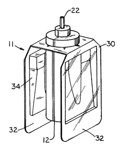
As shown in Figure 2, the enclosure shell, or shroud, 2 encloses a dual ca-
pacity refill unit 11, comprising a spray container 12, and a gel cartridge
dispenser
30. The shell or shroud, 2, is the exterior surface of the dispenser, and as
such is
subject to visual inspection as well as being picked up and handled during
spray
dispensing. Accordingly, the shell is desirably visually attractive and of
suitable
dimensions that it may be left in view in the area of usage for greatest
effective-
ness during evaporative dispensing. Preferably, the shell is constructed of a
durable, but economical, material such as plastic, glass, or ceramic. The gel
cartridge 30 is preferably a twin cartridge air freshener device of the type
taught in
U. S. Patent No. 5,788,155, of Martin et al.
Such an air freshener device comprises a pair of cartridge units
connected end-to-end by a flexible hinge portion, 31, adapted to engage, via
centering hole 33, the spray stem, 22, of a spray container, 12, and thus en-
gaged, to lie in parallel contiguous relationship to the lengthwise dimension
of
i5 said spray container. Thus positioned, as shown in Figures 2 - 5, the gel
car-
tridges overlay a substantial portion of the diameter and length of said spray
container, with the passive dispenser units on opposed sides of said spray
container, preferably proximate to the vent openings, 6, of the shell or
shroud, 2.
It is to be noted that the vapor permeable side of the gel package faces to
the
outside, i.e. away from the spray container, so as to obtain the greatest
available
permeation and flow of the volatile gel material through the permeable surface
to
the atmosphere. Figures 6 - 10 illustrate suitable embodiments of a passive
dispenser unit of the invention, with figures 8-10 illustrating a preferred
embodi-
ment. While the illustrations and the text of this description of the
invention speak
in terms of twin gel cartridge units, it is to be understood that any number
of twin
or individual passive dispensers may be used, spaced about the diameter of the
active dispenser container as desired, and comprising passive dispensers of
types other than gel dispensers, such as liquid containing cartridges,
impregnated
plastic evaporative units, impregnated paper units, blotters, etc. It is also
to be
understood that a single gel cartridge or passive dispenser unit may be
employed,
located so as to abut one side of said spray container and shell assembly, and
to
lie between said spray container and said shell, positioned properly either by
CA 02576101 2007-02-07
t , .
-13-
means of a cooperative fitting with the spray tip assembly of said spray
container
and said spray container, positioning ribs or protrusions on the inside of the
shell,
or a combination of such means. Further, one or more gel cartridges of other
passive dispenser units may be deployed in conjunction with one or more active
dispenser units, so as to provide a dispenser having a multitude of possible
dispersible materials. It is understood that the shell or shroud of the dual
capacity
dispenser is preferably an enclosure for the active and passive dispenser
units,
and as such thus creates an evaporation space for the passive dispenser, which
evaporation space communicates with the atmosphere by way of the vents, 6.
io The shell may be structured so as to have internal ribs and or protrusions
to
cooperatively engage the active dispenser or the passive dispenser, or both,
thus
providing means by which the consumer is prevented from improper placement of
the dispensers within the shell. When twin gel cartridge units, or plural
single
cartridge units, are employed, they may contain the same or differing
dispersible
is materials, and the consumer may activate any or all of said cartridges at
his or her
option, by removal of outer impermeable barrier membranes over the surfaces
thereof, prior to engagement with the shell. Thus, the consumer may choose to
utilize only one passive dispenser unit at a time, providing longer life for
the
passive dispenser. Alternatively, the consumer may choose to use multiple
20 passive dispenser units simultaneously, providing additional strength, or
if
differing dispersible materials are employed, providing a blend of the
consumers
choice. In addition to the possible use of the shell to comprise the passive
dispenser itself, a dispensing shell may be used to encompass another, inde-
pendent, passive dispenser, such as single or multiple gel cartridges, thus
25 providing for dispensing of multiple passive dispersibles. Moreover, it
is.also to
be understood that the passive dispenser means may lie outside the shell or
shroud, or may be attached directly to the active dispenser in the absence of
a
decorative shell or shroud, as shown, for example, in Figures 12 - 19. It is
also
possible for the performance of the passive dispenser to be enhanced, by such
30 means as provision of a fan to more rapidly draw air across the surface
thereof, or
by heating so as to cause more rapid evaporation of the volatile material.
CA 02576101 2007-02-07
-14-
Figure 3 illustrates the combination of the individual components of a dual
capacity refill cartridge, 11. As shown, the gel cartridge assembly, 30,
constitut-
ing a twin cartridge dispenser unit, is centered upon the spray container 12,
and
hangs downwardly on both sides thereof. Each gel cartridge, 32, comprises an
elongated shallow tray, 34, providing a reservoir for the storage of a
volatile
medium, with a thin permeable membrane sealing said reservoir enclosure, a
volatile dispersant medium in the reservoir enclosure, and a thin removable
impermeable membrane which is laminated coextensively with the permeable
membrane to prevent premature volatilization of the dispersant.
Figure 4 further illustrates the relationship of the component parts of a dual
capacity refill unit, in exploded view, showing the gel cartridge 30, which is
configured to be fitted across the top of the spray container 12, by means of
centering hole 33 in central portion 31, designed to pass over the top
surface, 26,
of the spray valve body, so as to come to rest in a force fit against the
upper
is vertical sides of the spray container. The spray container, 12, as
illustrated,
comprises a reservoir can 18, formed from a can body onto which a standard
spray valve, such as an aerosol valve which may be a metering valve, or a pump
spray valve, having valve stem 22, is located by means of valve crimp 24. The
spray valve body has a top surface 26, which is useful in centering the spray
can
in the shroud or shell into which the spray can is inserted either as a refill
or as
the initial spray container. When positioned within the shroud or shell, the
spray
can 18, having valve stem 22, is in fluid communication with spray nozzle
orifice
20, via spray tip 4 as seen in Figure 2. The spray valve is appropriately
actuated
by such means as a spray button, 3, as shown in Figures 1 and 2, or by such
other actuation means as may be selected by one skilled in the art. In
operation,
the spray control button 3 is depressed, actuating the spray container 12,
upon
demand. This results in a spray of dispersant being released from the spray
container as desired, to provide an immediate effect or to increase the
potency of
dispersible available to the consumer. It is preferred that the spray
container be
controlled by a dosage measuring spray valve, such that a specific amount of
dispersant is released from the spray container at each actuation. In such
actuation control, merely holding the spray button down does not result in a
CA 02576101 2007-02-07
-15-
continuous spray of dispersible from the container, which is wasteful and less
efficient than controlled dosage spraying. In addition, the gel cartridge
dispenser
releases dispersible at a predetermined and essentially constant rate, by
evapo-
ration, as a result of the vapor impermeable membrane having been removed, or
peeled, from the cartridge gel reservoirs, 34. The dispersible gel, which may
be
any of those known in the art, is restrained within the cartridge by a thin
vapor
permeable membrane, which permits evaporation of the dispersible at a pre-
established rate.
Figure 5 represents a cross sectional view of a dual capacity dispenser of
the present invention. The dispenser, 1, comprises shell 2, base 5, and a dual
capacity refill unit 11, which in turn comprises spray container 12, and gel
car-
tridge passive dispenser 30, having gel reservoir 34. The shell comprises a
spray
control button 3, with a spray tip 4, having spray nozzle orifice 22 therein
aligned
with the valve stem 22 of the spray container. The shell interlocks with base
5 by
means of latch opening 7, which aligns with the base latch opening 8. As illus-
trated, shell 2 also incorporates chamfer means 9, to receive and position
valve
stem 22 of the spray container as it is inserted into the shell, thus assuring
proper
alignment, as well as stop means, 10, to abut base 5, to prevent the consumer
from attempting to push the base and refill unit too far into the shell. Also
illus-
trated are rib protrusions 28, inside the shell, positioned to cooperatively
engage
the chamfered portion 29 of the gel cartridge, so as to properly align the gel
cartridge with the face of the shell and with the centrally located spray
container
12. By this arrangement, the consumer is assured-of being able to simply and
correctly insert a fresh dual capacity refill unit into the shell and base
assembly of
the dispenser as desired or as necessary. Of course, the consumer may also
choose to insert only one individual refill unit rather than both an active
dispenser
and a passive dispenser, if desired, thus replacing only the active dispenser,
or
only the passive dispenser, at will.
The prior art is generally aware of aerosol dispensers for dispensing pres-
surized materials into the air. See, for example, Adams et al, U. S. Patent
No.
5,358,147, Miller et al, U. S. Patent No. 5,862,960, and Miller et al, U. S.
Patent
No. 5,875,934. These refer-
CA 02576101 2007-02-07
-16-
ences relate to aerosol dispensers having refill cartridges for dispensing
such
compositions as perfumes into the air as an air freshener, or insect control
ingredients for home use. Such dispensers comprise an aerosol can to contain a
pressurized material to be dispensed, a nozzle having a delivery tube in fluid
s communication with the can and a spray orifice through which the pressurized
material can escape from the delivery tube, and valve means for controlling
the
release of the pressurized material into the nozzle delivery tube. In
addition, PCT
published Application W092/04419 discloses aerosol compositions packaged
within a metering valve aerosol having a high level of perfume. Formulations
and
io metering valves such as described in this patent can be used in the device
of the
present invention. Of particular utility in the present invention are those
aerosol
cartridges which fit within the outer shell of the presently described
dispenser, the
refill cartridge including a spray container having a can body and a valve
including
a valve stem, such as described by Adams et al, U. S. Patent No. 5,358,147.
The
is use of metering or metered dosage valves is of particular value, permitting
the
dispenser of the present invention to enable the consumer to employ a pre-
determined spray volume or dosage, and to utilize the spray feature of the
present invention for a predetermined number of applications. It has been
found
to be particularly useful to use a spray dispenser having a container of
approxi-
20 mately 60 to 200 ml capacity, preferably about 120 ml capacity, with a
metering
valve which dispenses from about 50 to about 250 sprays, preferably from about
60 to about 150, and most preferably from about 90 to about 100 sprays from
the
container before the container is empty or exhausted, dependent upon the needs
and/or usage patterns of the consumer.
25 Figure 6 represents an example of a gel cartridge assembly suitable for
use in the dispenser of the present invention, viewed from the side of the
remov-
able impermeable membrane which seals the reservoir enclosure shut. The twin
cartridges, joined end-to-end by flexible central hinge portion 31, having a
centering hole 33 therein, may be folded over at seams 35, and fit over the
top of
so a spray container, 12, the cartridges extending downwardly parallel to the
length
of the spray container, as illustrated in Figures 2 - 5. While Figure 6
illustrates an
air freshener cartridge device suitable for use in the present invention
having a
CA 02576101 2007-02-07
-17-
design printed upon the impermeable membrane which is removed to activate the
cartridge or cartridges, it is understood that no such design is necessary. As
illustrated in Figures 6 and 7, each of such twin cartridges, 32, is a
structural
assembly comprising an elongated shallow tray, 34, having side walls with an
upper edge flange, 36, which forms a peripheral margin around the open space
of
the tray, with a thin membrane, 38, which covers the open space of the tray 34
and is bonded to the flange peripheral margin. The membrane 38 forms a sealed
reservoir enclosure 39 within the tray interior, said membrane, 38, being
perme-
able to the vapor form of the volatile medium, 40, which is contained within
the
reservoir enclosure, but not the liquid or solid form. A thin, peelable,
impermeable
membrane, 41, is laminated coextensively with the permeable membrane to
prevent volatilization of the dispersant medium through the permeable membrane
38, from the reservoir enclosure, 39, prior to the intended utilization of the
cartridge. Activation of the cartridge is accomplished by removal, e.g.
peeling, of
the impermeable membrane 41. A gel cartridge dispenser, 30, such as shown in
Figure 6, has a semi-rigid structure, and- may be typically from about four to
eight
inches in length, about one half to one inch in width, and about one sixteenth
to
one half inch in thickness. A preferred volume of such a cartridge is
sufficient to
hold from about 2 to 4 grams of gel, but the volume may vary to contain from
0.5
to about 10 grams of gel. Such a dispenser may be utilized by peeling the
outer
impermeable membrane, 41, partially or completely from one cartridge, or
peeling
said outer impermeable membrane from both of the twin cartridges, and folding
the dispenser at seam lines 35 of hinge 31 so as to place the twin cartridges
approximately parallel to each other, and inserting the valve stem, 22, and
the top
surface of the spray valve body, 26, of a spray can, through hole 33, so as to
drape the passive dispenser down both sides of said spray can. It is clear
that
the reservoir enclosure may take a variety of shapes, and that various
configura-
tions thereof are possible, such as having ribs therein which serve both to
reinforce the enclosure and to key the enclosure into a conformational slotted
space in the dispenser shell. It is also evident that single reservoir
cartridges may
be provided, in which only one reservoir of dispersant is present, which may
be
utilized in alternative forms of dual capacity dispensers, or in the dual
capacity
CA 02576101 2007-02-07
-18-
dispenser of Figures 1 and 5, suitably modified for acceptance of such a
single
reservoir passive dispenser.
As illustrated in Figures 8 - 11, a preferred cartridge assembly may be
configured to fit the side of the active spray container 12. As shown, the
twin gel
cartridge 30, comprises a pair of reservoir enclosures 39 adjacent to a
central
hinge portion having centering hole 33 and folding seams or hinge points 35.
To
enable the individual dispenser cartridges to conform to the spray container
when
the twin gel cartridge dispense~ is folded and placed over the top thereof,
the
reservoir enclosures are provided with a conforming configuration, 42, shaped
to
fit about the side of the spray container and to accept the circumference
thereof.
It has also been found advantageous that the cartridges angle slightly
outwardly
from top to bottom of the spray container, at an angle of about 7 degrees from
the
vertical as measured at the hinge point of the cartridge. This angle assists
in
holding the refill unit in position in the shell, and contacting more of the
content of
the cartridge tray with the permeable membrane, as well as bringing the perme-
able membrane in closer proximity to the vent area of the shell or shroud of
the
dispenser. The area of the shell which is cut away or removed to form the vent
area should be in proximity to the dispensing area of the cartridge, i.e. the
area of
permeable membrane which is uncovered by removal of the impermeable surface
membrane. Further, it has been found advantageous that the open area of the
vents correspond to approximately 25 to 90 percent, preferably 40 to 60
percent,
and most preferably 45 to 55 percent of the surface area of the permeable
membrane through which the dispersant is released, to achieve control of the
rate
of release of the dispersant so as to maintain the desired dispensing life. It
is
desired that the dispenser have a useful life span of up to two months, about
60
days, preferably about one month, or thirty days. While this rate of
dispensing
may, alternatively, be controlled by selection of the porosity of the
permeable
membrane and the volatility of the dispersant, it has been found that control
of the
vent surface area ratio, i.e. the ratio of the area of the open vent in the
shell to the
area of the exposed permeable membrane, is the simplest manner in which one
may directly effect the length of time that the cartridge will continue to
dispense
vapor. That is, the greater the amount of vent area aligned with the
dispensing
CA 02576101 2007-02-07
-19-
surface of the passive dispenser, the more rapidly said passive dispenser will
disperse its volatile content. It is also considered feasible that the vent
area be
adjustable, by such means as sliding members which control the area of vent
opening which is open or closed, so as to permit more or less rapid
evaporation of
the content of the cartridge, in accordance with the personal preference or
needs
of the consumer. An example of such a sliding member would be a plastic plate
conforming to the inside of the shell proximate the vent openings, and adapted
to
be removed, or displaced either vertically or horizontally so as to adjust the
area
of vent openings which are open for circulation of air from the interior to
the
exterior of the shell.
The elongated tray, 34, may be constructed -by either injection or thermo-
form molding of a thermoplastic polymer such as polyethylene, polypropylene,
polyvinyl chloride, and the like. In a preferred embodiment, end-to-end
attached
trays 34, and interconnecting flexible hinge band 31, are thermoformed as a
is unitary structure, and preferably include folding seams 35 to facilitate a
90 degree
fold. The thin film vapor-impermeable membrane 41 is bonded to thin film vapor-
permeable membrane 38 in the form of a laminate. Vapor-impermeable film 41 is
peelable,.so that its removal allows volatile dispersant ingredient 40 to
migrate
through vapor-permeable membrane 38 and volatilize into the atmosphere.
Removable or peelable membrane 41 can be adapted for removal from both
cartridge units at the same time, or from each cartridge unit independently.
Vapor-permeable membrane 38 can be in the form of a flexible thin film of a
thermoplastic polymer such as polyethylene, isotactic polypropylene, cellulose
acetate, and the like. Membrane 38 permits migration of the enclosed volatile
dispersant ingredient 40, either as a liquid or a vapor, depending on the type
of
membrane employed. Membrane 38 may be a microporous type, having submi-
cron pores, such as isotactic hydrophobic polypropylene film sold under the
tradename CELGARD, by Celanese, Inc. Microporous thermoplastic polymer
films are described in U.S. Patent No. 3,055,297. It is also advantageous
that the vapor permeable membrane, 38, which encloses the dispersible
material in the gel cartridge be transparent, or minimally opaque, so as to
permit observation of the contents of the reservoir enclosure by the
CA 02576101 2007-02-07
-20-
consumer, so as to permit the consumer to judge the remaining life span of the
cartridge, and thus to observe when replacement is appropriate. This is also
true
for cartridges in which the passive dispersible is in the form of an
evaporative
solid or liquid rather that a gel.
Vapor impermeable membrane 41 may be in the form of a flexible thin film
such as aluminum foil or nylon film, which is peelable from its adhering bond
to
vapor-permeable membrane 38. In a preferred embodiment, a laminate of
membrane 41 and membrane 38 is preformed, and then- applied to tray 34 to
cover the open interior, and heat-sealed along periphery flange 36 to enclose
the
reservoir content of dispersible ingredient 40. The dispersible ingredient 40
can
be any, ddispersible material which can migrate through membrane 38 and dis-
perse into the atmosphere in vapor form.
In addition to the configurations illustrated in Figures 1- 11, it is possible
to
provide dispensers such as illustrated in Figures 12 - 19, wherein the passive
is dispenser maybe attached directly to the spray container, or to the
decorative
shell itself, or to an overcap for the spray container, for example.
In one embodiment, Figures 12 and 13 illustrate a dual capacity dispenser
comprising separate active and passive dispenser units, wherein the passive
dispenser is removably attached directly to the exterior circumference of the
active spray container. In this manner, the consumer may readily replace one
or
the other dispenser without replacing both. As shown, a conventional spray
container, 51, such as an aerosol air freshener, may be provided with a clip-
on
collar type of passive dispenser, 52. Such a clip-on dispenser may readily be
fashioned of economical materials, such as plastic, having sufficient
elasticity that
it may readily be forced over the diameter of the spray container. Advanta-
geously, as shown in Figure 13, such a clip-on dispenser may comprise a slot,
opening, or receptacle, 53, for positioning a gel cartridge dispenser 54, or
other
passive dispenser, preferably in juxtaposition to vent openings 56 in said
clip-on
dispenser, which permit circulation of air into and away from the passive dis-
penser, 54. Alternatively, the passive dispenser may simply comprise a single
gel
dispenser cartridge, 54, which may be directly attached to the surface
diameter of
the spray container, 51, or other form of active dispenser, by such means as
an
CA 02576101 2007-02-07
-21-
adhesive backing, as shown in Figure 14. As such an externally applied dis-
penser, the passive dispenser may take the form of a gel dispenser, an impreg-
nated plastic strip, a saturated porous medium, a plastic container of the
"break to
activate" type, or any other suitable form of passive release medium, suitably
adhered to or attached to the active dispenser.
Still further, the passive dispenser means may be incorporated directly into
the cap or cover of an active dispenser, such as shown in Figure 15. This type
of
active dispenser comprises a spray dispenser 51, such as an aerosol dispenser,
and refill cartridges therefore, with the outside cap or shell having the
passive
dispenser, in the form of a gel dispenser, for example, built directly into
the shell,
inserted therein, or attached thereto. This type of dispenser could be very
similar
in appearance to the dispenser of Figure 1, but with the passive dispenser
being
a separate unit, a part of the shell or cover rather than part of a dual
refill unit. As
shown in Figure 15, spray dispenser 51 is encompassed or fitted with a
dispenser
cap, 55, having interactive relationship with the spray mechanism, 57 of the
spray
dispenser. A gel cartridge, 54, or other passive dispenser, is fitted into a
receiving
pocket or slot in the dispenser cap 55, so as to place the evaporative surface
area
thereof in juxtaposition with vent openings 56, in the dispenser cap.
Still another embodiment is shown in Figures 16 and 17, wherein the
overcap 55 is, in itself, a container or reservoir for a solid, liquid or gel
passive
dispersible, 59. In this case, the impermeable barrier 58 may be external to
the
vent openings, 56, in the shell or overcap. The overcap may be provided with
one or more vent areas, 56, which are sealed by the peelable or removable
impermeable barrier 58 when provided to the ultimate consumer, who then may
choose to open one or more of said vent areas to obtain the desired level of
dispensing of passive dispersible. As in the previous embodiment, the overcap
55 may be designed so as to fit over and cooperatively engage the spray dis-
pensing means 57 of a spray dispenser can, 51. In this type of dispenser,
merely
pushing downwardly on the overcap or shell will activate the spray dispensing
means, providing a burst of active dispersant. In such an embodiment, the
consumer may replace either or both of the active dispensing means (the spray
container and spray dispensing means assembly) and the passive dispensing
CA 02576101 2007-02-07
-22-
means (the overcap, containing the passive dispersant) at any given time.
Since
each dispensing means may contain one of a number of different dispersants, a
large number of alternatives are available to the consumer.
Similarly, the dual capacity dispenser may take the form of a low profile
dispenser, comprising a low tray or container of passive dispersible partially
or
entirely encircling or encompassing an active spray container, as shown in
Figures 18 and 19. In this embodiment, a low profile top housing, 60, having
vent
openings 66 about all or part of its periphery, is fitted over a low profile
passive
dispenser, 61, which encompasses a central spray dispenser, 62. As with the
previously discussed embodiment, the top housing, 60, may cooperatively
engage the spray dispenser mechanism 63 of the spray dispenser, such that
merely pushing downwardly on said top housing will cause a burst of active
dispersible to be released. The top housing may be removably attached to the
passive dispenser, 61, such as by threading, clip action, compression fit, or
other
conventional joining means which permit ready removal. The passive dispenser,
61, comprises a container, 64, preferably having a low profile, which contains
a
passive dispersible 65. The passive dispersible may constitute a solid, a
liquid, or
a gel, and is protected by a peel away foil 67 or impermeable barrier which is
adhered to the top flange 68 of the container 64.
In addition to the above-described embodiments, other appropriate
arrangements combining an active dispensing means and a passive dispensing
means will be apparent to one skilled in the art. For example, a bellows means
for expulsion of saturated air would constitute a suitable active dispenser,
since it
is dependent upon an action of the consumer to deliver dispersible material to
the
atmosphere, while saturation of the air to be dispensed may be accomplished by
evaporation of a dispersible from a reservoir of passively dispersible
material into
a separate reservoir for dispersion by the action of the bellows. Further,
passive
dispensers may be considered to include such means as heated substrates which
are impregnated or saturated with a liquid passive dispersible, as well as
heated
gel cartridges, solid dispersibles, or the like. Still further, passive
dispensers may
be combined with such air flow means as fans, either spring driven or
electric, to
increase the distribution of passively dispensed dispersibles. Active
dispensers
CA 02576101 2007-02-07
-23-
are understood to include pumps, aerosols, propellant driven dispensers, and
bladder contraction means or bellows. In addition to the dual capacity
dispensers
described hereinabove, the invention includes dispensers having both active
and
passive dispensers wherein the passive dispenser is heated and/or subjected to
s forced air flow, such as in a battery operated or plug-in unit, wherein said
unit
also comprises a button or nozzle activated dispenser, i.e. an active
dispenser.
Such a dispenser would be of particular interest for such locations as a
kitchen
counter, where it could be plugged into a wall outlet for enhanced passive
provision of an air freshener, while remaining available for a spray discharge
of an
io actively dispersed material such as a fragrance or deodorizer.
Typically, an ingredient suitable for inclusion in the evaporative cartridge,
or passive dispenser, for the present invention is a fragrance, air freshener,
deodorizer, odor eliminator, malodor counteractant, insecticide, insect
repellant,
medicinal substance, disinfectant, sanitizer, mood enhancer, aroma therapy
15 composition, or the like, in liquid or gel form, although gels are
preferred for the
present invention. Preferably, the fragrance or air freshener is a fragrance
comprising one or more volatile organic compounds which are available from
perfumery suppliers such as Firmenich Inc., Takasago Inc., Noville Inc., Quest
Co., Intemational Flavors & Fragrances, and Givaudan-Roure Corp. Most
20 conventional fragrance materials are volatile essential oils. The fragrance
can be
a synthetically formed material, or a naturally derived oil such as oil of
Bergamot,
Bitter Orange, Lemon, Mandarin, Caraway, Cedar Leaf, Clove Leaf, Cedar Wood,
Geranium, Lavender, Orange, Origanum, Petitgrain, White Cedar, Patchouli,
Lavandin, Neroli, Rose absolute, and the like.
25 A wide variety of chemicals are known for perfumery, such as aldehydes,
ketones, esters, alcohols, terpenes, and the like. A fragrance can be
relatively
simple in composition, or can be a complex mixture of natural and synthetic
chemical components. Synthetic types of fragrance compositions either alone or
in combination with natural oils are described in U. S. Patent Nos. 4,324,915;
30 4,411,829; and 4,434,306. Other artificial liquid fragrances include
geraniol, geranyl acetate, eugenol, isoeugenol, linalool, linalyl
CA 02576101 2007-02-07
-24-
acetate, phenethyl alcohol, methyl ethyl ketone, methylionone, isobomyl
acetate,
and the like.
A liquid fragrance may also be formed into a thixotropic gel by the addition
of a thickening agent, such as a cellulosic material, a polymeric thickener,
or a
fumed silica of the type marketed under the Cabosil trademark by Cabot Corpora-
tion. A fragrance ingredient can also be in the form of a crystalline solid,
which
has the ability to sublime into the vapor phase at ambient temperatures. A
crystalline fragrance starting material can be selected from organic compounds
which include vanillin, ethyl vanillin, coumarin, tonalid, calone,
heliotropene, musk
xylol, cedrol, musk ketone benzophenone, raspberry ketone, methyl naphthyl
ketone beta, phenyl ethyl salicylate, veltol, maltol, maple lactone,
proeugenol
acetate, evemyl, and the like. This type of fragrance can contribute a long
term
air-treatment capability to an air freshener dispenser device for use in the
present
invention. Many of such fragrances are also suitable for adaptation to be used
in
is the spray dispensing mode of the present invention.
Example I
A dual function air freshener was prepared in the configuration of Figure 1,
using an active liq,uid spray unit comprising a complex floral fragrance,
comprising
Takasago RE 3792/E, and a passive time release cartridge having a gel therein
comprising a companion fragrance, Takasago RI 1962/2. The liquid dispenser
had a dose metering valve such that the refill unit was capable of spraying 90
measured sprays of the air freshener. The gel cartridge, after removal of the
impermeable membrane covering the gel, released air freshener for a period of
about 30 days, with a vent opening area in the shell of approximately 48
percent
of the area of exposed gel. It was found that in normal usage, both the spray
dispenser and the gel dispenser were essentially exhausted or empty after
about
days.
30 Example 2
A dual function dispenser was prepared in accordance with the configura-
tion of Figure 1, having a spray dispenser of Takasago RE 3792/E fragrance,
and
CA 02576101 2007-02-07
-25-
a vapor dispenser comprising a long term dispenser of Takasago RI 1962/2
fragrance. This dispenser was compared to a Glade Plug-In dispenser having
the same fragrance as the passive dispenser, for a 30 day period, and found to
have greater utility in that an instant effect of the fragrance was readily
available
from the active mode of the dual capacity dispenser. The passive dispenser,
with
a 47% venting area, was found in acceptance testing to be "too strong" after 3
days by 3 percent of evaluators, while the plug-in was found to be "too
strong"
after 3 days by 19 percent. Conversely, the passive mode of the dual capacity
dispenser was evaluated as "just right" by 88 percent, while the plug-in was
so
evaluated by 79 percent. After 30 days, the passive mode of the dual capacity
dispenser was considered "just right" by 58 percent, and "too weak" by 37
percent
of evaluators, while the plug-in was considered "just right" by 67 percent,
and "too
weak" by only 19 percent of the evaluators. These evaluations reflect the fact
that
the dual capacity passive mode dispenser was nearing complete loss of dispersi-
is ble material at the end of 30 days, while the plug-in unit had a larger
amount of
dispersible material remaining and continued to dispense such material at a
higher rate than the other.
Example 3
A spray unit dispenser of a deodorizer composition is combined with a
passive dispenser of air freshener attached thereto by a clip-on collar. By
spray-
ing of the deodorizer, the consumer may address malodors or smoke as desired,
while the passive dispenser of the air freshener creates a background atmos-
phere of a pleasant scent.
Example 4
A dual capacity refill unit was prepared, comprising a spray dispenser of a
complex floral fragrance, with a twin gel cartridge unit comprising a gel form
of a
companion fragrance. Upon exhaustion of the dispenser reservoirs of Example 1,
this dual capacity refill unit was placed in the shell to replace the
exhausted active
and passive dispensers. The dispenser unit was then available for continued
use
for an additional period of time.
CA 02576101 2007-02-07
-26-
Example 5
A single gel cartridge comprising a complex floral fragrance is prepared,
and used to replace only the passive dispenser in the clip-on collar of the
dual
capacity dispenser of Example 3, illustrating the freedom of the consumer to
replace one dispenser without replacement of the other.
Example 6
A dual capacity dispenser is prepared for insect control. A spray dispenser
of insecticide is encircled with a low profile container of a volatile insect
repellant.
The volatile material is covered by a foil, which is removed for activation of
the
insect repellant. This dispenser is suitable for use as a long-term insect
repellant
dispenser, with a spray unit for rapid attack upon insects if they should
appear to
the consumer.
is
Exam Ip e 7
A spray can of sanitizer is prepared as an active dispenser, incorporating
an odor eliminator in the overcap as a passive dispenser. An aerosol air sani-
tizer, comprising triethylene glycol plus a suitable fragrance as the
dispersible
sanitizer spray, with a standard spray valve, is combined with a charcoal odor
absorber, in the form of particulate carbon glued to a woven backing to
maximize
air flow. This dual capacity dispenser is found to have great utility in the
kitchen
and bath areas.
From the above discussion, examples, and Figures, it may be seen that
the present invention comprises a multiple capacity dual function dispenser
for
dispersible ingredients, such as a fragrances or air fresheners. By dual use
or
dual capacity, it is meant that at least two differing modes of distribution
are
included and utilized in a single dispenser apparatus, and that the two are
independent of each other. In the preferred embodiment, the dispenser appara-
tus comprises an active, short term, or immediate provider, such as a spray
dispenser, in conjunction with a long term or time effective passive dispenser
of
the evaporation mode, i.e. a container of an evaporative medium.
CA 02576101 2007-02-07
-27-
Relative to the short term, or spray medium, it is preferred that metered
dosage spray containers be used, so that controlled amounts of medium are
released at any given time of use. In this manner, a predetermined number of
sprays, or applications, may be provided for, by predetermination of the
volume of
the spray container, the pressurization thereof, and the volume of medium
released with each spray application by the consumer. In this manner, one may
predict, based upon statistical analysis of typical consumer utilization, the
life
expectancy of the spray unit, and accordingly select a long term or
evaporative
component of the dual capacity dispenser to have a similar life expectancy, at
io normal or ambient temperatures of consumption. In such a manner, when both
modes of dispensing are exhausted at approximately the same time, the con-
sumer is most likely to note and react to the need for refill or replacement
of the
dispenser. It is a preferred embodiment of the present invention that the
spray
container and evaporative medium container, preferably a gel container, be
is replaced at the same time, in the form of a dual capacity refill unit,
comprising
both a spray container and a gel container of the same or complementary air
fresheners or fragrances. Such refill units may be provided as a unitary
structure
or package for simultaneous purchase, or may be provided as complementary
structures or packages for separate purchase by the consumer for later combina-
20 tion and insertion into the shell or shroud of the dispenser, which need
not be
replaced upon exhaustion or consumption of the contents thereof. As is the
case
of the "Lasting Mist " dispenser device commercially available from S. C. John-
son & Son, Inc. of Racine, Wisconsin, the dispenser of the present invention
may
comprise a body that accepts a replaceable cartridge, which a user or consumer
as inserts into an open cartridge receptacle. Thus, the dispenser may be
configured
so as to accept a refill unit comprising a mated set of replacement units for
the
spray container and the gel or evaporative medium container, or,
alternatively, the
dispenser may be configured so that spray container and evaporative medium
container may be replaced independently of each other. It is understood that
by
30 the term "independently of each other", the simultaneous replacement of
both
units is not precluded, but that it is intended that the consumer has the
option to
replace either or both of the spray container and the evaporative medium con-
CA 02576101 2007-02-07
-28-
tainer at any given time, and that replacement of both at one time is neither
required nor precluded. Thus, the active and passive dispenser units, and the
refill units thereof, need not be attached to each other, or for that matter,
to the
external shell or outside of the dual capacity dispenser. It may readily be
seen
that refill units may be placed within the shell in an unattached manner,
with, for
example, the passive unit merely resting between the actives dispenser and the
shell.
Spray containers suitable for use with the present invention may, in
general, comprise an aerosol or pump dispenser can comprising a containment
volume for the medium to be sprayed, and a valve stem which communicates with
a spray nozzle orifice of the dispenser. Said can may be activated by
actuation
means included in the dispenser shell or shroud into which the can may be
inserted for use, or the spray container may come complete with actuation
means, e.g. a spray nozzle assembly, for use with altemate dispensers. The
spray container may be provided with a spray medium of choice, selected from
the various spray media available, such as fragrances, insecticides,
medicinals,
etc, under pressure within the containment vessel, generally a metallic
canister of
the type well known in the art. A valve stem and nozzle orifice are provided,
providing a fluid communication between the pressurized media in the can, and
with the spray tip through which the pressurized media can escape from the
valve
stem. The spray delivery system further includes valve means for controlling
the
release of the pressurized material, into the spray orifice, the valve means
being
manually operable by the user. Preferably the valve means is a conventional
aerosol valve. The preferred valve employed as the means for controlling the
release of the pressurized material or media is a valve that delivers a
single,
metered discharge of pressurized material each time the valve stem is
actuated.
In any event, the valve means is manually operable by the user of the dual
function dispenser. In general, the shell of the dispenser of the present
invention
is so shaped as to be conveniently and comfortably held in the hand of the
user
when it is desired to employ the spray medium. However, it is also desired
that
the shell of the dispenser be so shaped as to be decorative and non-intrusive,
so
that it may be left in plain view for dispensing of the evaporative medium.
Thus,
CA 02576101 2007-02-07
-29-
the shell of the dispenser, and the dispenser means associated therewith, may
comprise a shell which is simply pressed downwardly to activate the spray
mechanism, while the dispenser is left in view on a counter or table top, as a
decorative item which acts as a passive dispenser of the same or a different
material as is dispensed by the spray.
Although it is possible for the aerosol can and associated hardware to be
permanently mounted within the shell or shroud of the dispenser of the
invention,
it is preferred instead that inner surfaces of the dispenser shell be so
configured
that the aerosol can, its associated valve stem, and the evaporative media
3.0 container and related structures may comprise a single unit which is
removable
from the shell and replaceable by a refill unit comprising like elements.
An advantage of the present invention is the constant release of an air
freshener, for example, from the evaporative cartridge, or passive dispenser,
which thus provides a constant and long-term effect, while the consumer may,
at
his or her option, increase the effect of the said air freshener by actuating
the
spray container to obtain additional air freshener or fragrance, for example,
as
desired or required. it is also considered within the scope of the present
invention
to utilize differing compositions for the active spray component and the
passive
component, to provide differing effects. For example, the spray component
might
be an odor eliminator, to allow one to overcome offensive odors such as in a
kitchen or bathroom, while the passive dispenser could be a perfume, to
provide a
pleasant ambient scent to a room or given area when serious offensive odors
are
not present. Similarly, one may provide a spray dispenser of an insect
repellant
or insecticide, in conjunction with a long-term passive dispenser of
insecticide or
insect growth regulator.
It is also to be understood that the term volatile material as used in con-
junction with the passively dispersed dispersant, is intended to refer to a
material
which is subject to evaporation or vaporization as its primary means of
distribu-
tion. This is not to imply that the actively dispersed materials may not be
"volatile"
so in the normal sense of the word, since such materials as perfumes and fra-
grances are obviously volatile. The distinction to be drawn is that
distinction
between active dispersement and passive dispersement, with the term volatile
CA 02576101 2007-02-07
-30-
reserved herein to refer to those materials which are passively dispensed,
i.e.
those which are dispersed by vaporization or volatilization .
Further, when it is indicated that the actively dispensed material and the
passively dispensed material may be "the same", it is not intended to imply
that
the two are chemically identical, but that the two may belong to the same
class or
group of suitable materials, such as to indicate that both are fragrances,
both are
sanitizers, both are insecticides, and so forth. As previously indicated, it
is well
known that a given specific composition may not function well as both a
passive
dispersant and as an active, or sprayed, dispersant. However, when it is indi-
cated that the actively dispensed material and the passively dispensed
material
differ", it is intended to imply that the two are not chemically identical,
but not to
preclude the possibility that both belong to the same class or group of disper-
sants. Thus, it is possible that the active and passive dispersibles may
differ, but
may both be fragrances, for example.
is While the present invention has been described with respect to what are at
present considered to be the preferred embodiments, it is to be understood
that
the invention is not to be limited to the disclosed embodiments. For example,
the
disclosure has been exemplified in terms of fragrances and air fresheners,
while it
is clear that other dispersible materials, such as insect repellents, and
other
dispersibles mentioned hereinabove may be utilized. Accordingly, the invention
is
intended to cover various modifications and equivalent arrangements within the
spirit and scope of the appended.claims. The scope of the following claims is
to
be accorded the broadest interpretation so as to encompass all such modifica-
tions and equivalent formulations and functions.
INDUSTRIAL APPLICABILITY
The practical usefulness of the dual function dispenser and refill cartridges
disclosed herein, with respect to the dispensing of dispersible media
convention-
ally delivered by an aerosol delivery system, or by evaporation, including, by
way
of example only, air fragrancing or insect control dispersible ingredients and
the
CA 02576101 2007-02-07
-31-
like, will be readily apparent to those skilled in the art. Except for the
aerosol can,
all the parts described may be made from suitable plastics by conventional
molding or other plastic fabrication techniques. The aerosol can may be made
in
conventional ways from aluminum or other suitable metals, with a conventional
metered or unmetered valve means. The evaporative medium container may be
made from plastics, metal, paper, ceramic, or laminated stock, or combinations
thereof.