Note: Descriptions are shown in the official language in which they were submitted.
CA 02576197 2009-11-05
1
SYNTHETICALLY EXPEDIENT WATER-DISPERSIBLE IR DYES HAVING IMPROVED
LIGHTFASTNESS
Field of the Invention
The present application relates to infrared (IR) dyes, in particular near-IR
dyes, which are synthetically
accessible in high yield and which are dispersible in an aqueous ink base. It
has been developed primarily to allow
facile preparation of dyes suitable for use in inkjet inks.
Background of the Invention
IR absorbing dyes have numerous applications, such as optical recording
systems, thermal writing displays,
laser filters, infrared photography, medical applications and printing.
Typically, it is desirable for the dyes used in
these applications to have strong absorption in the near-IR at the emission
wavelengths of semiconductor lasers (e.g.
between about 700 and 2000 nm, preferably between about 700 and 1000 nm). In
optical recording technology, for
example, gallium aluminium arsenide (GaAIAs) and indium phosphide (InP) diode
lasers are widely used as light
sources.
Another important application of IR dyes is in inks, such as printing inks.
The storage and retrieval of
digital information in printed form is particularly important. A familiar
example of this technology is the use of
printed, scannable bar codes. Bar codes are typically printed onto tags or
labels associated with a particular product
and contain information about the product, such as its identity, price etc.
Bar codes are usually printed in lines of
visible black ink, and detected using visible light from a scanner. The
scanner typically comprises an LED or laser
(e.g. a HeNe laser, which emits light at 633 nm) light source and a photocell
for detecting reflected light. Black dyes
suitable for use in barcode inks are described in, for example, W0031074613.
However, in other applications of this technology (e.g. security tagging) it
is desirable to have a barcode, or
other intelligible marking, printed with an ink that is invisible to the
unaided eye, but which can be detected under
UV or IR light.
An especially important application of detectable invisible ink is in
automatic identification systems, and
especially "netpage" and "HyperlabelTM" systems.
In general, the netpage system relies on the production of, and human
interaction with, netpages. These
are pages of text, graphics and images printed on ordinary paper, but which
work like interactive web pages.
Information is encoded on each page using ink which is substantially invisible
to the unaided human eye. The ink,
however, and thereby the coded data, can be sensed by an optically imaging pen
and transmitted to the netpage
system.
Active buttons and hyperlinks on each page may be clicked with the pen to
request information from the
network or to signal preferences to a network server. In some forms, text
written by hand on a netpage may be
automatically recognized and converted to computer text in the netpage system,
allowing forms to be filled in. In
CA 02576197 2009-11-05
2
other forms, signatures recorded on a netpage may be automatically verified,
allowing e-commerce transactions to
be securely authorized.
Netpages are the foundation on which a netpage network is built. They may
provide a paper-based user
interface to published information and interactive services.
A netpage consists of a printed page (or other surface region) invisibly
tagged with references to an
online description of the page. The online page description is maintained
persistently by a netpage page server. The
page description describes the visible layout and content of the page,
including text, graphics and images. It also
describes the input elements on the page, including buttons, hyperlinks, and
input fields. A netpage allows markings
made with a netpage pen on its surface to be simultaneously captured and
processed by the netpage system.
Multiple netpages can share the same page description. However, to allow input
through otherwise
identical pages to be distinguished, each netpage is assigned a unique page
identifier. This page ID has sufficient
precision to distinguish between a very large number of netpages.
Each reference to the page description is encoded in a printed tag. The tag
identifies the unique page on
which it appears, and thereby indirectly identifies the page description. The
tag also identifies its own position on
the page.
Tags are printed in infrared-absorptive ink on any substrate which is infrared-
reflective, such as ordinary
paper. Near-infrared wavelengths are invisible to the human eye but are easily
sensed by a solid-state image sensor
with an appropriate filter.
A tag is sensed by an area image sensor in the netpage pen, and the tag data
is transmitted to the netpage
system via the nearest netpage printer. The pen is wireless and communicates
with the netpage printer via a short-
range radio link. Tags are sufficiently small and densely arranged that the
pen can reliably image at least one tag
even on a single click on the page. It is important that the pen recognize the
page ID and position on every
interaction with the page, since the interaction is stateless. Tags are error-
correctably encoded to make them partially
tolerant to surface damage.
The netpage page server maintains a unique page instance for each printed
netpage, allowing it to
maintain a distinct set of user-supplied values for input fields in the page
description for each printed netpage.
HyperlabelTM is a trade mark of Silverbrook Research Pty Ltd, Australia. In
general, HyperlabelTM
systems use an invisible (e.g. infrared) tagging scheme to uniquely identify a
product item. This has the significant
advantage that it allows the entire surface of a product to be tagged, or a
significant portion thereof, without
impinging on the graphic design of the product's packaging or labeling. If the
entire surface of a product is tagged
("omnitagged"), then the orientation of the product does not affect its
ability to be scanned i.e. a significant part of
the line-of-sight disadvantage of visible barcodes is eliminated. Furthermore,
if the tags are compact and massively
replicated (` omnitags"), then label damage no longer prevents scanning.
Thus, hyperlabelling consists of covering a large portion of the surface of a
product with optically-
readable invisible tags. When the tags utilize reflection or absorption in the
infrared spectrum, they are referred to as
infrared identification (IRID) tags. Each Hyperlabel tag uniquely identifies
the product on which it appears. The
tag may directly encode the product code of the item, or it may encode a
surrogate ID which in turn identifies the
product code via a database lookup. Each tag also optionally identifies its
own position on the surface of the product
item, to provide the downstream consumer benefits of netpage interactivity.
CA 02576197 2009-11-05
3
HyperlabelsTM are applied during product manufacture and/or packaging using
digital printers, preferably
inkjet printers. These may be add-on infrared printers, which print the tags
after the text and graphics have been
printed by other means, or integrated colour and infrared printers which print
the tags, text and graphics
simultaneously.
HyperlabelsTM can be detected using similar technology to barcodes, except
using a light source having
an appropriate near-IR frequency. The light source may be a laser (e.g. a
GaAIAs laser, which emits light at 830 nm)
or it may be an LED.
From the foregoing, it will be readily apparent that invisible IR detectable
inks are an important component
of netpage and HyperlabelTM systems. In order for an IR absorbing ink to
function satisfactorily in these systems, it
should ideally meet a number of criteria:
(i) compatibility with inkjet printers;
(ii) compatibility of the IR dye with aqueous solvents used in inkjet inks;
(iii) intense absorption in the near infra-red region (e.g. 700 to 1000 nm);
(iv) zero or low intensity visible absorption;
(v) lightfastness;
(vi) thermal stability;
(vii) zero or low toxicity;
(viii) low-cost manufacture;
(ix) adheres well to paper and other media; and
(x) no strikethrough and minimal bleeding of the ink on printing.
Hence, it would be desirable to develop IR dyes and ink compositions
fulfilling at least some and
preferably all of the above criteria. Such inks are desirable to complement
netpage and HyperlabelTM systems.
Some IR dyes are commercially available from various sources, such as Epolin
Products, Avecia Inks and
H.W. Sands Corp.
In addition, the prior art describes various IR dyes. US 5,460,646, for
example, describes an infrared
printing ink comprising a colorant, a vehicle and a solvent, wherein the
colorant is a silicon (IV) 2,3-
naphthalocyanine bis-trialkylsilyloxide.
US 5,282,894 describes a solvent-based printing ink comprising a metal-free
phthalocyanine, a complexed
phthalocyanine, a metal-free naphthalocyanine, a complexed naphthalocyanine, a
nickel dithiolene, an aminium
compound, a methine compound or an azulenesquaric acid.
However, none of the prior art dyes can be formulated into ink compositions
suitable for use in netpage or
HyperlabelTM systems. In particular, commercially available and/or prior art
inks suffer from one or more of the
following problems: absorption at wavelengths unsuitable for detection by near-
IR sensors; poor solubility or
dispersibility in aqueous solvent systems; or unacceptably high absorption in
the visible part of the spectrum.
In a typical netpage, there may be a large number of hyperlinks on one page
and correspondingly relatively
large areas of the page printed with IR ink. In the HyperlabelTM system, the
majority of a product's packaging may
be printed with the invisible ink. Thus, it is especially desirable that the
ink used is invisible to the unaided eye and
contains minimal residual colour.
CA 02576197 2009-11-05
4
Moreover, inkjet printing is the preferred means for generating netpages and
HyperlabelsTM. Inkjet printing
is preferred primarily for its high-speed and low cost. Inkjet inks are
typically water-based for reasons of low cost,
low toxicity and low flammability. In thermal bubble jet printers, the ink
needs to be rapidly vaporized during the
printing process. This rapid vaporization of the ink during the printing
process necessitates a water-based ink
composition. Accordingly, it is desirable that the IR dyes used in netpage and
HyperlabelTM inks are suitable for
formulating into aqueous ink compositions and are compatible with inkjet
printers.
A further essential requirement of IR dyes used in netpage systems is that
they must absorb IR radiation at
a frequency complementary to the frequency of the IR sensor in the netpage
pen. Preferably, the ink should contain
a dye, which absorbs strongly at the frequency of the IR sensor. Accordingly,
the dyes used in netpage systems
should absorb strongly in the near-IR region - that is, 700 to 1000 nm,
preferably 750 to 900 nm, more preferably
780 to 850 nm.
With the anticipated widespread use of netpage and HyperlabelTM, it would be
especially desirable to
develop a low-cost near-IR dye which can be prepared in high yields on an
industrial scale, and which is acceptably
light stable.
Summary of the Invention
In a first aspect, the present invention provides an IR-absorbing
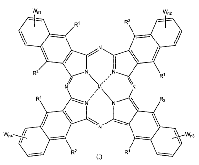
naphthalocyanine dye of formula (I):
Wnl Wn2
-I_ Ry R2
/N
R2 N\ .N ` R'
N M N
Rt NN R2
N
%4\ Wn3
RZ (I) W
wherein
M is selected from Ga(A');
Al is an axial ligand selected from -OH, halogen (preferably Cl), -OR3, -
OC(O)R , a hydrophilic ligand and/or a
ligand suitable for reducing cofacial interactions;
R' and R2 may be the same or different and are selected from hydrogen or C,_12
alkoxy (preferably C1-6 alkoxy);
CA 02576197 2009-11-05
R3 is selected from C1.12 alkyl, C5.12 aryl, C5-12 arylalkyl or
Si(R")(RY)(Rz); and
R is selected from C1.12 alkyl, C5-12 aryl or C5.12 arylalkyl
R", RY and RZ may be the same or different and are selected from C1-12 alkyl,
C5.12 aryl, C5.12 arylalkyl, CI-12 alkoxy,
C5-12 aryloxy or C5-12 arylalkoxy;
5 W is a hydrophilic group;
n1 is 0, 1, 2 or 3;
n2 is 0, 1,2or3;
n3 is 0, 1, 2 or 3;
n4 is 0, 1,2or3;
provided that at least one of n1, n2, n3 or n4 is greater than 0.
In a second aspect, the present invention provides an inkjet ink comprising a
dye as described above.
In a third aspect, the present invention provides an inkjet printer comprising
a printhead in fluid
communication with at least one ink reservoir, wherein said at least one ink
reservoir comprises an inkjet ink as
described above.
In a fourth aspect, the present invention provides an ink cartridge for an
inkjet printer, wherein said ink
cartridge comprises an inkjet ink as described above.
In a fifth aspect, the present invention provides a substrate having a dye as
described above disposed
thereon.
In a sixth aspect, there is provided a method of enabling entry of data into a
computer system via a printed
form, the form containing human-readable information and machine-readable
coded data, the coded data being
indicative of an identity of the form and of a plurality of reference points
of the form, the method including the steps
of:
receiving, in the computer system and from a sensing device, indicating data
regarding the identity of the
form and a position of the sensing device relative to the form, the sensing
device, when placed in an operative
position relative to the form, generating the indicating data using at least
some of the coded data;
identifying, in the computer system and from the indicating data, at least one
field of the form; and
interpreting, in the computer system, at least some of the indicating data as
it relates to the at least one
field,
wherein said coded data comprises an IR-absorbing dye as described above.
In a seventh aspect, there is provided a method of enabling entry of data into
a computer system via a
printed form, the form containing human-readable information and machine-
readable coded data, the coded data
being indicative of at least one field of the form, the method including the
steps of
receiving, in the computer system and from a sensing device, indicating data
regarding the at least one field
and including movement data regarding movement of the sensing device relative
to the form, the sensing device,
when moved relative to the form, generating the data regarding said at least
one field using at least some of the
coded data and generating the data regarding its own movement relative to the
form; and
interpreting, in the computer system, at least some of said indicating data as
it relates to said at least one
field,
wherein said coded data comprises an IR-absorbing dye as described above.
CA 02576197 2009-11-05
6
In an eighth aspect, there is provided a method of enabling entry of data into
a computer system via a
product item, the product item having a printed surface containing human-
readable information and machine-
readable coded data, the coded data being indicative of an identity of the
product item, the method including the
steps of.
(a) receiving, in the computer system and from a sensing device, indicating
data regarding the identity of the
product item, the sensing device, when placed in an operative position
relative to the product item, generating the
indicating data using at least some of the coded data; and
(b) recording, in the computer system and using the indicating data,
information relating to the product item,
wherein said coded data comprises an IR-absorbing dye as described above.
In a ninth aspect, there is provided a method of enabling retrieval of data
from a computer system via a
product item, the product item having a printed surface containing human-
readable information and machine-
readable coded data, the coded data being indicative of an identity of the
product item, the method including the
steps of:
(a) receiving, in the computer system and from a sensing device, indicating
data regarding the identity of the
product item, the sensing device, when placed in an operative position
relative to the product item, generating the
indicating data using at least some of the coded data;
(b) retrieving, in the computer system and using the indicating data,
information relating to the product item;
and
(c) outputting, from the computer system and to an output device, the
information relating to the product item,
the output device selected from the group comprising a display device and a
printing device,
wherein said coded data comprises an IR-absorbing dye as described above.
Brief Description of Drawings
Figure 1 is a schematic of a the relationship between a sample printed netpage
and its online page
description;
Figure 2 is a schematic view of a interaction between a netpage pen, a Web
terminal, a netpage printer, a
netpage relay, a netpage page server, and a netpage application server, and a
Web server;
Figure 3 illustrates a collection of netpage servers, Web terminals, printers
and relays interconnected via
a network;
Figure 4 is a schematic view of a high-level structure of a printed netpage
and its online page description;
Figure 5a is a plan view showing the interleaving and rotation of the symbols
of four codewords of the
tag;
Figure 5b is a plan view showing a macrodot layout for the tag shown in Figure
5a;
Figure 5c is a plan view showing an arrangement of nine of the tags shown in
Figures 5a and 5b, in
which targets are shared between adjacent tags;
Figure 5d is a plan view showing a relationship between a set of the tags
shown in Figure 5a and a field
of view of a netpage sensing device in the form of a netpage pen;
Figure 6 is a perspective view of a netpage pen and its associated tag-sensing
field-of-view cone;
Figure 7 is a perspective exploded view of the netpage pen shown in Figure 6;
CA 02576197 2009-11-05
7
Figure 8 is a schematic block diagram of a pen controller for the netpage pen
shown in Figures 6 and 7;
Figure 9 is a perspective view of a wall-mounted netpage printer;
Figure 10 is a section through the length of the netpage printer of Figure 9;
Figure IQa is an enlarged portion of Figure 10 showing a section of the
duplexed print engines and glue
wheel assembly;
Figure 11 is a detailed view of the ink cartridge, ink, air and glue paths,
and print engines of the netpage
printer of Figures 9 and 10;
Figure 12 is an exploded view of an ink cartridge;
Figure 13 is a schematic view of the structure of an item ID;
Figure 14 is a schematic view of the structure of an omnitag;
Figure 15 is a schematic view of a pen class diagram;
Figure 16 is a schematic view of the interaction between a product item, a
fixed product scanner, a hand-
held product scanner, a scanner relay, a product server, and a product
application server;
Figure 17 is a perspective view of a bi-lithic printhead;
Figure 18 an exploded perspective view of the bi-lithic printhead of Figure
17;
Figure 19 is a sectional view through one end of the bi-lithic printhead of
Figure 17;
Figure 20 is a longitudinal sectional view through the bi-lithic printhead of
Figure 17;
Figures 21(a) to 21(d) show a side elevation, plan view, opposite side
elevation and reverse plan view,
respectively, of the bi-lithic printhead of Figure 17;
Figures 22(a) to 22(c) show the basic operational principles of a thermal bend
actuator;
Figure 23 shows a three dimensional view of a single ink jet nozzle
arrangement constructed in accordance
with Figure 22;
Figure 24 shows an array of the nozzle arrangements shown in Figure 23;
Figure 25 is a schematic cross-sectional view through an ink chamber of a unit
cell of a bubble forming
heater element actuator;
Figure 26 shows an absorption spectrum for 1,2-
di(naphthalocyaninatogalliumoxo)ethane
(NcGaOCH2CH2OGaNc) in NMP;
Figure 27 shows an absorption spectrum for hydroxygallium
naphthalocyaninetetrasulfonic acid in DMSO;
Figure 28 shows an absorption spectrum for hydroxygallium
naphthalocyaninetetrasulfonic acid
tetra(triethylammonium) salt in DMSO;
Figure 29 shows an absorption spectrum for hydroxygallium
naphthalocyaninetetrasulfonyl chloride
(CISO2)4NcGaOH in DMSO;
Figure 30 shows an absorption spectrum for sulfonamide 5 in DMSO from Example
2;
Figure 31 shows a lightfastness testing apparatus;
Figure 32 shows reflectance spectra for Epson Black 890;
Figure 33 shows reflectance spectra for an inkjet ink comprising a
hydroxygallium naphthalocyanine
prepared in Example 1 at 2.24mM dye concentration;
Figure 34 shows reflectance spectra for an ink et ink comprising a
hydroxygallium naphthalocyanine
prepared in Example 1 at 4.49 mM dye concentration;
CA 02576197 2009-11-05
8
Figure 35 shows reflectance spectra for an inkjet ink comprising a
hydroxygallium naphthalocyanine
prepared in Example 1 at 7.46 mM dye concentration;
Figure 36 shows reflectance spectra for an inkjet ink comprising a
hydroxygallium naphthalocyanine
prepared in Example 1 at 3.0 mM dye concentration;
Figure 37 shows reflectance spectra for an ink et ink comprising a
hydroxygallium naphthalocyanine
prepared in Example 2 at 3.0 mM dye concentration; and
Figure 38 shows reflectance spectra for an inkjet ink comprising a
hydroxygallium naphthalocyanine
prepared in Example 2 at 3.0 mM dye concentration.
Detailed Description
IR Absorbing Dye
As used herein, the term "IR-absorbing dye" means a dye substance, which
absorbs infrared radiation and
which is therefore suitable for detection by an infrared sensor. Preferably,
the IR-absorbing dye absorbs in the near
infrared region, and preferably has a ? ,, in the range of 700 to 1000 mn,
more preferably 750 to 900 nm, more
preferably 780 to 850 nm. Dyes having a A,. in this range are particularly
suitable for detection by semiconductor
lasers, such as a gallium aluminium arsenide diode laser.
Dyes according to the present invention have the advantageous features of
absorption in the IR (preferably
near-IR) region; suitability for formulation into aqueous inkjet inks; and
facile preparation. Moreover, their high
extinction coefficients in the near-IR region means that the dyes appear
"invisible" at a concentration suitable for
detection by a near-IR detector (e.g. a netpage pen). Accordingly, the dyes of
the present invention are especially
suitable for use in netpage and HyperlabelTM applications. None of the dyes
known in the prior art has this unique
combination of properties.
Generally, the naphthalocyanine dyes according to the present invention are
synthesized via a cascaded
coupling of four 2,3-dicyanonapthalene (1) molecules, although they may also
be prepared from the corresponding
imidine (2).
NH
CN
I I N
CN
(2) NH2
The cascaded base-catalysed macrocyclisation may be facilitated by metal
templating, or it may proceed in
the absence of a metal. If macrocylisation is performed in the absence of a
templating metal, then a metal may be
readily inserted into the resultant metal-free napthalocyanine.
The hydrophilic groups represented as W are usually introduced into the dye
molecule after
macrocyclisation via an electrophilic aromatic substitution reaction. Aromatic
substitution may not occur entirely
I i
CA 02576197 2009-11-05
9
symmetrically and, hence, each naphthalene unit in the macrocycle may contain
different numbers of the
hydrophilic groups represented as W.
The hydrophilic group W imparts water-dispersibility or water-solubility on
the dye molecule. The dye
molecules of the present invention are intended for use in inkjet ink
compositions, preferably aqueous inkjet ink
compositions. Hence, the provision of a hydrophilic group W allows the dye
molecules of the present invention to
be dispersed in an aqueous inkjet ink composition. The suffix (e.g. "ni")
indicates the number of W groups present
on each naphthalene ring. For example, when nl = 2, there are two hydrophilic
W groups on the first naphthalene
unit. The suffixes nl, n2, n3 and n4 may be the same or different. Preferably
nl+n2+n3+n4 (= n) is between 2 and 4.
Preferably nl = 1, n2 = 1, n3 = 1 and n4 = 1
Preferably, the hydrophilic group W is selected from a substituent comprising
a hydrophilic polymer chain;
a substituent comprising an ammonium group; a substituent comprising an acid
group including salts thereof; or a
substituent comprising a sulfonamide group.
An example of a hydrophilic polymeric chain is a PEG chain, which may comprise
from 2 to 5000
repeating units of ethylene glycol. Other hydrophilic polymer chains will be
readily apparent to the person skilled in
the art. Preferably, the hydrophilic polymer chain is of formula -
(OCH2CH2)bORb (wherein b is an integer from 2 to
5000 and Rb is H, Cl.g alkyl or C(O)C1.8 alkyl).
An ammonium group may be present as a substituent comprising a group of
general formula -
N+(R`)(Rb)(R ) or -U, wherein R', Rb, R` may be the same or different and are
independently selected from H, Cl.g
alkyl (e.g. methyl, ethyl, cyclohexyl, cyclopentyl, tert-butyl, iso-propyl
etc.), C&12 arylalkyl (e.g. benzyl, phenylethyl
etc.) or C6-12 aryl (e.g. phenyl, naphthyl etc.); and U is pyridinium,
imidazolinium or pyrrolinium.
An acid group may be present as a substituent comprising a group of formula -
CO2Z, -SO3Z, -OSO3Z,
-P03Z2 or -0PO3Z2, wherein Z is H or a water-soluble cation. Preferably, Z is
selected from Li+, Na', K+ or an
ammonium cation, such as N+(Rr)(R )(RS)(R`) wherein Rm, R , R', R` may be the
same or different and are
independently selected from H, C1_& alkyl (e.g. methyl, ethyl, cyclohexyl,
cyclopentyl, tert-butyl, iso-propyl etc.), C6-
12 arylalkyl (e.g. benzyl, phenylethyl etc.) or C6.12 aryl (e.g. phenyl,
naphthyl etc.). Methods of introducing acid
groups, such as those described above, will be well known to the person
skilled in the art. For example, a sulfonic
acid group (-SO3H) may be introduced directly onto the naphthalene ring by
sulfonation using, for example, oleum
or chlorosulfonic acid. Conversion of the acid group to its salt form can be
effected using, for example, a metal
hydroxide reagent (e.g. LiOH, NaOH or KOH) or a metal bicarbonate (e.g.
NaHCO3). Non-metal salts may also be
prepared using, for example, an ammonium hydroxide (e.g. Bu4NOH, NH4OH etc.).
A sulfonamide group may be of general formula -SO2NR Rq, wherein R" and R9 are
independently selected
from H, C1_8 alkyl (e.g. methyl, ethyl, cyclohexyl, cyclopentyl, tert-butyl,
isopropyl etc.), -(CH2CH2O)eRe (wherein
e is an integer from 2 to 5000 and Re is H, C1_s alkyl or C(O)C1_g alkyl), C6-
12 arylalkyl (e.g. benzyl, phenylethyl etc.)
or C6-12 aryl (e.g phenyl, methoxyphenyl etc.). Sulfonamides may be readily
prepared from the corresponding
sulfonic acids. Moreover, mixtures of sulfonic acids/salts and sulfonamides
are also contemplated within the scope
of the present invention. For example, each dye molecule may comprise 1, 2, 3
or 4 sulfonamide groups and 1, 2, 3
or 4 sulfonic acid ammonium salts, with the total number of W groups being 4.
CA 02576197 2009-11-05
The hydrophilic group W may be a sulfonamide group of general formula -
SO2NHR", wherein R'3 is of
formula (V):
Rl
(V)
wherein:
5 R' is selected from H, C1-12 alkoxy, -(OCH2CH2)dORd;
d is an integer from 2 to 5000; and
e is H, C,.8 alkyl or C(O)C1_8 alkyl.
R' may be positioned at the ortho, meta or para positions, but is usually
positioned at the para position.
The groups represented by R1 and R2 may be used for modifying or "tuning" the
wavelength of A,,,, of the
10 dye. Electron-donating substituents (e.g. alkoxy) at the ortho positions
can produce a red-shift in the dye. In one
preferred embodiment of the present invention, R1 and R2 are both C,.8 alkoxy
groups, preferably butoxy. Butoxy
substituents advantageously shift the A,. towards longer wavelengths in the
near infrared, which are preferable for
detection by commercially available lasers. In another preferred embodiment R1
and R2 are both hydrogen, which
provides an expeditious synthesis of the requisite naphthalocyanines.
The central metal atom M has been found, surprisingly, to have a very
significant impact on the light
stability of the compounds of the present invention. Previously, it was
believed that the nature of the organic
naphthalocyanine chromophore was primarily responsible for the rate at which
such compounds degrade. However,
it has now been found that certain metal naphthalocyanines show unusually high
light stability compared to other
metals. Specifically, gallium and copper naphthalocyanines have been shown to
exhibit very good light stability,
making these compounds highly suitable for netpage and HyperlabelTM
applications in which the IR dye may be
exposed to office lighting or sunlight for a year or more. Gallium compounds
are particularly preferred since these
have a more red-shifted A, compared to copper. A more red-shifted X,,, is
preferred, because colored cyan dyes
are less likely to interfere with the IR dye's response to the netpage pen.
A' may be selected to add axial steric bulk to the dye molecule, thereby
reducing cofacial interactions
between adjacent dye molecules.
Preferably, the axial ligand, when present, adopts a conformation (or is
configured) such that it effectively
"protects" or blocks a n-face of the dye molecule. An axial ligand, which can
form an "umbrella" over the lt-system
and reduce cofacial interactions between adjacent dye molecules is
particularly suitable for use in the present
invention.
It has been recognized by the present inventors that IR-absorbing dye
compounds of the prior art absorb, at
least to some extent, in the visible region of the spectrum. Indeed, the vast
majority of IR-absorbing dye compounds
known in the prior art are black. This visible absorption is clearly
undesirable in "invisible" IR inks, especially IR
inks for use in netpage or HyperlabelTM systems.
CA 02576197 2009-11-05
11
It has further been recognized by the present inventors that the presence of
visible bands in the IR spectra
of IR-absorbing dye compounds, and particularly IR-absorbing metal-ligand
complexes, is mainly due to cofacial
interactions between adjacent molecules.
Typically, IR-absorbing compounds comprise a at-system which forms a
substantially planar moiety in at
least part of the molecule. There is a natural tendency for planar it-systems
in adjacent molecules to stack on top of
each other via cofacial it-interactions, known as Tt-it stacking. Hence, IR-
absorbing compounds have a natural
tendency to group together via cofacial it-interactions, producing relatively
weakly bound dimers, trimers etc.
Without wishing to be bound by theory, it is understood by the present
inventors that 7t-7t stacking of IR-absorbing
compounds contributes significantly to the production of visible absorption
bands in their IR spectra, which would
not otherwise be present in the corresponding monomeric compounds. This
visible absorption is understood to be
due to broadening of IR absorption bands when it-systems stack on top of each
other and it-orbitals interact,
producing small changes in their respective energy levels. Broadening of IR
absorption bands is undesirable in two
respects: firstly, it reduces the intensity of absorption in the IR region;
secondly, the IR absorption band tends to tail
into the visible region, producing highly coloured compounds.
Furthermore, the formation of coloured dimers, trimers etc. via 7t-7t
interactions occurs both in the solid
state and in solution. However, it is a particular problem in the solid state,
where there are no solvent molecules to
disrupt the formation of extended it-stacked oligomers. IR dyes having
acceptable solution characteristics may still
be intensely coloured solids when printed onto paper. The ideal "invisible" IR
dye should remain invisible when the
solvent has evaporated or wicked into the paper.
Additionally, the interaction of it-orbitals with local charges or partially
charged atoms, such as ions, can be
large and this may introduce additional absorption in the visible region.
Specific examples of moieties suitable for reducing cofacial interactions are
described in more detail
below. Dendrimers, for example, are useful for exerting maximum steric
repulsion since they have a plurality of
branched chains, such as polymeric chains. However, it will be appreciated
from the above that any moiety or group
that can interfere sufficiently with the cofacial 7t-n interactions of
adjacent dye molecules will be suitable for
minimizing visible absorption, and will therefore be suitable for use in the
present invention.
Generally, it is preferable to configure the dye molecule such that the
average distance between the it-
systems of adjacent molecules is greater than about 3.5 A, more preferably
greater than about 4 A, more preferably
greater than about 4.5 A and more preferably greater than about 5 A. This
preferred distance between the it-systems
of adjacent molecules is based on theoretical calculations. From theoretical
studies by the present inventors, it is
understood that it-7t interactions are significant at a distance of
3.5 A or less.
Alternatively (or in addition), A' may be selected to add further
hydrophilicity to the dye molecule to
increase its water-dispersibility. Hence, A' may include a hydrophilic group,
such as any one of the groups defined
as W above.
In order to introduce axial steric bulk and/or increase hydrophilicity, A' may
be a dendrimer. In one
preferred form A' is a ligand of formula (IIIa):
CA 02576197 2009-11-05
12
0--(CH2)gl EE.I- (CH2)P1-O P1
gl
(IIla)
wherein:
C' represents a core unit having two or more branching positions;
each P' is independently selected from H, a hydrophilic moiety or a branched
moiety;
g' is an integer from 2 to 8;
q' is 0 or an integer from 1 to 6; and
each p' is independently selected from 0 or an integer from 1 to 6.
Preferably, the core unit C' is selected from a C atom, an N atom, a Si atom,
a
Cl_g alkyl residue, a C3.9 cycloalkyl residue, or a phenyl residue. The core
unit C' has at least two branching
positions, the number of branching positions corresponding to the value of g'.
Hence, an axial ligand having 3
branching positions and a carbon atom core (i.e. g' = 3; C' = C atom) may be,
for example, a pentaerythritol
derivative of formula (A):
P'O
O OP,
PlO
(A)
Each P' group in formula (IIIa) may be the same or different. For example, in
a pentaerythritol derivative
(having three branching positions), there may be two arms bearing terminal
hydroxyl groups (-CH2OH; P' = H) and
one arm bearing a sulfate group (-CH2OSO3Z; P' = SO3Z).
Preferably, P' is a hydrophilic moiety. The hydrophilic moiety may be an acid
group (including salts
thereof), a sulfonamide group, a hydrophilic polymer chain or an ammonium
group.
Accordingly, P' may comprise a hydrophilic polymer chain, such as a PEG chain.
Hence, in some
embodiments, P' may be of formula: (CH2CH2O),R6, wherein v is an integer from
2 to 5000 (preferably 2 to 1000,
preferably 2 to 100) and R6 is H, C1.6 alkyl or C(O)C1_8 alkyl.
Alternatively, P1 may comprise an acid group (including salts thereof), such
as sulfonic acids, sulfates,
phosphonic acids, phosphates, carboxylic acids, carboxylates etc. Hence, in
some embodiments P' maybe of
formula: SO3Z, P03Z2, CI-12 alkyl-CO2Z, C1-12 alkyl-SO3Z or C1_12-alkyl-PO3Z2,
CI-12 alkyl-OSO3Z or Cl_12-alkyl-
OP03Z2 wherein Z is H or a water-soluble cation. Examples of water-soluble
cations are Li+, Na+, K+, NH4+ etc.
Alternatively, P' may comprise an ammonium group, such as a quaternary
ammonium group. Hence, in
some embodiments P1 may be of formula: C1_12-alkyl-N+(R8)(10b)(R ) or C1.12
alkyl-U, wherein R', Rb, R` may be the
same or different and are independently selected from H, Cl_g alkyl (e.g.
methyl, ethyl, cyclohexyl, cyclopentyl, tert-
CA 02576197 2009-11-05
13
butyl, iso-propyl etc.) or C6-12 arylalkyl (e.g. benzyl, phenylethyl etc. Or
C6..12 aryl (e.g. phenyl, naphthyl etc.) and U
is pyridinium, imidazolinium or pyrrolinium.
Alternatively, P1 may comprise a sulfonamide group, such as a group of general
formula -SO2NR"Rq,
wherein R" and Rq are independently selected from H, C1.8 alkyl (e.g. methyl,
ethyl, cyclohexyl, cyclopentyl, tert-
butyl, iso-propyl etc.), -(CH2CH2O)eRe (wherein e is an integer from 2 to 5000
and Re is H, Cl_g alkyl or C(O)C1_8
alkyl), C6-12 arylalkyl (e.g. benzyl, phenylethyl etc.) or Cr112 aryl (e.g.
phenyl, methoxyphenyl etc.).
Branched structures such as those described above are generally known as
dendrimers. Dendrimers are
advantageous since their branched chains maximize the effective three-
dimensional volume of the axial ligand and,
in addition, provide the potential for introducing a plurality of hydrophilic
groups into the dye molecule. The
pentaerythritol structure shown in formula (A) is an example of a simple
dendrimer suitable for use in the present
invention. Further examples are triethanolamine derivatives (B),
phloroglucinol derivatives (C), and 3,5-
dihydroxybenzyl alcohol derivatives (D):
/o oP~
N
OP1
P'O OP1
O \ OPT
TI (C) TI ~) O
In an alternative embodiment, one or more of the P' groups is itself a
branched moiety. The branched
moiety may be any structure adding further branching to the axial ligand, such
as a moiety of formula (IIIb):
(CH2)g2 C2 (CH2)p2-O P2
__ je
(IIIb)
wherein:
C2 represents a core unit having two or more branching positions;
P2 is H or a hydrophilic moiety;
g2 is an integer from 2 to 8;
q2 is 0 or an integer from 1 to 6;
CA 02576197 2009-11-05
14
p2 is 0 or an integer from I to 6;
Preferred forms of C2 and P2 correspond to the preferred forms of C' and P1
described above. A specific
example of an axial ligand, wherein Pl is a branched moiety of formala (IIIb)
is dipentaerythritol derivative (E):
HO HO
O O OH
HO HO
(E)
Alternatively, the branched moiety may comprise multiple randomized branched
chains, based on motifs of
core units linked by alkylene or ether chains. It will be readily understood
that randomized dendrimer structures may
be rapidly built up by, for example, successive etherifications of
pentaerythritol with further pentaerythritol, 3,5-
dihydroxybenzyl alcohol or triethanolamine moieties. One or more terminal
hydroxyl groups on the dendrimer may
be capped with hydrophilic groups, such as any of the hydrophilic groups above
described. The extent of
hydrophilic capping may be used to control the water-solubility of the dye
molecule.
It will be appreciated that randomized branched structures cannot be readily
illustrated using precise
structural formulae. However, all branched dendrimer-like structures are
contemplated within the scope of the above
definitions of A.
The term "hydrocarbyl" is used herein to refer to monovalent groups consisting
generally of carbon and
hydrogen. Hydrocarbyl groups thus include alkyl, alkenyl and alkynyl groups
(in both straight and branched chain
forms), carbocyclic groups (including polycycloalkyl groups such as
bicyclooctyl and adamantyl) and aryl groups,
and combinations of the foregoing, such as alkylcycloalkyl,
alkylpolycycloalkyl, alkylaryl, alkenylaryl, alkynylaryl,
cycloalkylaryl and cycloalkenylaryl groups. Similarly, the term
"hydrocarbylene" refers to divalent groups
corresponding to the monovalent hydrocarbyl groups described above.
Unless specifically stated otherwise, up to four -C-C- and/or -C-H moieties in
the hydrocarbyl group
may be optionally interrupted by one or more moieties selected from -0-; -NR"-
; -S-; -C(O)-; -C(O)O-;
-C(O)NR"'-; -S(O)-; -SO2-; -SO2O-; -SO2NR"'-; where R'" is a group selected
from H, C1-12 alkyl, C6.12 aryl or
C6_12 arylalkyl.
Unless specifically stated otherwise, where the hydrocarbyl group contains one
or more -C=C- moieties,
up to four -C=C- moieties may optionally be replaced by -C=N-. Hence, the term
"hydrocarbyl" may include
moieties such as heteroaryl, ether, thioether, carboxy, hydroxyl, alkoxy,
amine, thiol, amide, ester, ketone, sulfoxide,
sulfonate, sulfonamide etc.
Unless specifically stated otherwise, the hydrocarbyl group may comprise up to
four substituents
independently selected from halogen, cyano, nitro, a hydrophilic group as
defined above (e.g. -SO3H, -S03K,
-CO2Na, -NH3}, -NMe3+ etc.) or a polymeric group as defined above (e.g. a
polymeric group derived from
polyethylene glycol).
CA 02576197 2009-11-05
As used herein, the term "bridged cyclic group" includes C4-30 carbocycles
(preferably C6 20 carbocycles)
containing 1, 2, 3 or 4 bridging atoms. Examples of bridged carbocyclic groups
are bornyl and triptycenyl, and
derivatives thereof. The term "bridged cyclic group" also includes bridged
polycyclic groups, including groups such
as adamantanyl and tricyclo[5.2. 1.0]decanyl, and derivatives thereof.
5 Unless specifically stated otherwise, the term "bridged cyclic group" also
includes bridged carbocycles
wherein 1, 2, 3 or 4 carbon atoms are replaced by heteroatoms selected from N,
S or 0 (i.e. bridged heterocycles).
When it is stated that a carbon atom in a carbocycle is replaced by a
heteroatom, what is meant is that -CH- is
replaced by -N-, -CH2- is replaced by -0-, or -CH2- is replaced by -S-. Hence,
the term "bridged cyclic group"
includes bridged heterocyclic groups, such as quinuclidinyl and tropanyl.
Unless specifically stated otherwise, any
10 of the bridged cyclic groups may be optionally substituted with 1, 2, 3 or
4 of the substituents described below.
The term "aryl" is used herein to refer to an aromatic group, such as phenyl,
naphthyl or triptycenyl. C6.12
aryl, for example, refers to an aromatic group having from 6 to 12 carbon
atoms, excluding any substituents. The
term "arylene", of course, refers to divalent groups corresponding to the
monovalent aryl groups described above.
Any reference to aryl implicitly includes arylene, where appropriate.
15 The term "heteroaryl" refers to an aryl group, where 1, 2, 3 or 4 carbon
atoms are replaced by a heteroatom
selected from N, 0 or S. Examples of heteroaryl (or heteroaromatic) groups
include pyridyl, benzimidazolyl,
indazolyl, quinolinyl, isoquinolinyl, indolinyl, isoindolinyl, indolyl,
isoindolyl, furanyl, thiophenyl, pyrrolyl,
thiazolyl, imidazolyl, oxazolyl, isoxazolyl, pyrazolyl, isoxazolonyl,
piperazinyl, pyrimidinyl, piperidinyl,
morpholinyl, pyrrolidinyl, isothiazolyl, triazolyl, oxadiazolyl, thiadiazolyl,
pyridyl, pyrimidinyl, benzopyrimidinyl,
benzotriazole, quinoxalinyl, pyridazyl, coumarinyl etc. The term
"heteroarylene", of course, refers to divalent
groups corresponding to the monovalent heteroaryl groups described above. Any
reference to heteroaryl implicitly
includes heteroarylene, where appropriate.
Unless specifically stated otherwise, aryl, arylene, heteroaryl and
heteroarylene groups may be optionally
substituted with 1, 2, 3, 4 or 5 of the substituents described below.
Where reference is made to optionally substituted groups (e.g. in connection
with bridged cyclic groups,
aryl groups or heteroaryl groups), the optional substituent(s) are
independently selected from C1_8 alkyl, C1.8 alkoxy,
-(OCH2CH2)dORd (wherein d is an integer from 2 to 5000 and Rd is H, C1.8 alkyl
or C(O)CI-8 alkyl), cyano, halogen,
amino, hydroxyl, thiol, -SR", -NR R", nitro, phenyl, phenoxy, -CO2R", -C(O)W, -
OCOR", -SO2R", -OSO2R",
-SO20R", -NHC(O)R", -CONR"R", -CONR R", -S02NR"R", wherein R" and R" are
independently selected from
hydrogen, C1_12 alkyl, phenyl or phenyl-Cl_8 alkyl (e.g. benzyl). Where, for
example, a group contains more than one
substituent, different substituents can have different R" or R" groups. For
example, a naphthyl group may be
substituted with three substituents: -SO2NHPh, -CO2Me group and NH2.
The term "alkyl" is used herein to refer to alkyl groups in both straight and
branched forms, The alkyl
group may be interrupted with 1, 2 or 3 heteroatoms selected from 0, N or S.
The alkyl group may also be
interrupted with 1, 2 or 3 double and/or triple bonds. However, the term
"alkyl" usually refers to alkyl groups having
no heteroatom interruptions or double or triple bond interruptions. Where
"alkenyl" groups are specifically
mentioned, this is not intended to be construed as a limitation on the
definition of "alkyl" above.
CA 02576197 2009-11-05
16
The term "alkyl" also includes halogenoalkyl groups. A C1_12 alkyl group may,
for example, have up to 5
hydrogen atoms replaced by halogen atoms. For example, the group -OC(O)C1.12
alkyl specifically includes
-OC(O)CF3.
Where reference is made to, for example, C1-12 alkyl, it is meant the alkyl
group may contain any number of
carbon atoms between 1 and 12. Unless specifically stated otherwise, any
reference to "alkyl" means Cl_i2 alkyl,
preferably C1-6 alkyl.
The term "alkyl" also includes cycloalkyl groups. As used herein, the term
"cycloalkyl" includes
cycloalkyl, polycycloalkyl, and cycloalkenyl groups, as well as combinations
of these with linear alkyl groups, such
as cycloalkylalkyl groups. The cycloalkyl group may be interrupted with 1, 2
or 3 heteroatoms selected from 0, N or
S. However, the term "cycloalkyl" usually refers to cycloalkyl groups having
no heteroatom interruptions. Examples
of cycloalkyl groups include cyclopentyl, cyclohexyl, cyclohexenyl,
cyclohexylmethyl and adamantyl groups.
The term "arylalkyl" refers to groups such as benzyl, phenylethyl and
naphthylmethyl.
The term "halogen" or "halo" is used herein to refer to any of fluorine,
chlorine, bromine and iodine.
Usually, however, halogen refers to chlorine or fluorine substituents.
Where reference is made to "a substituent comprising..." (e.g. "a substituent
comprising a hydrophilic
group", "a substituent comprising an acid group (including salts thereof)", "a
substituent comprising a polymeric
chain" etc.), the substituent in question may consist entirely or partially of
the group specified. For example, "a
substituent comprising an acid group (including salts thereof)" may be of
formula -(CH2)j-SO3K, wherein j is 0 or
an integer from 1 to 6. Hence, in this context, the term "substituent" may be,
for example, an alkyl group, which has
a specified group attached. However, it will be readily appreciated that the
exact nature of the substituent is not
crucial to the desired functionality, provided that the specified group is
present.
Chiral compounds described herein have not been given stereo-descriptors.
However, when compounds
may exist in stereoisomeric forms, then all possible stereoisomers and
mixtures thereof are included (e.g.
enantiomers, diastereomers and all combinations including racemic mixtures
etc.).
Likewise, when compounds may exist in a number of regioisomeric forms, then
all possible regioisomers
and mixtures thereof are included.
For the avoidance of doubt, the term "a" (or "an"), in phrases such as
"comprising a", means "at least one"
and not "one and only one". Where the term "at least one" is specifically
used, this should not be construed as
having a limitation on the definition of "a".
Throughout the specification, the term "comprising", or variations such as
"comprise" or "comprises",
should be construed as including a stated element, integer or step, but not
excluding any other element, integer or
step.
In 'et Inks
The present invention also provides an inkjet ink. Preferably, the inkjet ink
is a water-based inkjet ink-
Water-based inkjet ink compositions are well known in the literature and, in
addition to water, may
comprise additives, such as co-solvents, biocides, sequestering agents,
humectants, pH adjusters, viscosity
modifiers, penetrants, wetting agents, surfactants etc.
CA 02576197 2009-11-05
17
Co-solvents are typically water-soluble organic solvents. Suitable water-
soluble organic solvents include
C1-4 alkyl alcohols, such as ethanol, methanol, butanol, propanol, and 2-
propanol; glycol ethers, such as ethylene
glycol monomethyl ether, ethylene glycol monoethyl ether, ethylene glycol
monobutyl ether, ethylene glycol
monomethyl ether acetate, diethylene glycol monomethyl ether, diethylene
glycol monoethyl ether, diethylene
glycol mono-n-propyl ether, ethylene glycol mono-isopropyl ether, diethylene
glycol mono-isopropyl ether, ethylene
glycol mono-n-butyl ether, diethylene glycol mono-n-butyl ether, triethylene
glycol mono-n-butyl ether, ethylene
glycol mono-t-butyl ether, diethylene glycol mono-t-butyl ether, 1-methyl-l-
methoxybutanol, propylene glycol
monomethyl ether, propylene glycol monoethyl ether, propylene glycol mono-t-
butyl ether, propylene glycol mono-
n-propyl ether, propylene glycol mono-isopropyl ether, dipropylene glycol
monomethyl ether, dipropylene glycol
monoethyl ether, dipropylene glycol mono-n-propyl ether, dipropylene glycol
mono-isopropyl ether, propylene
glycol mono-n-butyl ether, and dipropylene glycol mono-n-butyl ether;
formamide, acetamide, dimethyl sulfoxide,
sorbitol, sorbitan, glycerol monoacetate, glycerol diacetate, glycerol
triacetate, and sulfolane; or combinations
thereof.
Other useful water-soluble organic solvents include polar solvents, such as 2-
pyrrolidone, N-
methylpyrrolidone, s-caprolactam, dimethyl sulfoxide, sulfolane, morpholine, N-
ethylmorpholine, 1,3-dimethyl-2-
imidazolidinone and combinations thereof.
The inkjet ink may contain a high-boiling water-soluble organic solvent which
can serve as a wetting agent
or humectant for imparting water retentivity and wetting properties to the ink
composition. Such a high-boiling
water-soluble organic solvent includes one having a boiling point of 180 C or
higher. Examples of the water-soluble
organic solvent having a boiling point of 180 C or higher are ethylene glycol,
propylene glycol, diethylene glycol,
pentamethylene glycol, trimethylene glycol, 2-butene-1,4-diol, 2-ethyl-1,3-
hexanediol, 2-methyl-2,4-pentanediol,
tripropylene glycol monomethyl ether, dipropylene glycol monoethyl glycol,
dipropylene glycol monoethyl ether,
dipropylene glycol monomethyl ether, dipropylene glycol, triethylene glycol
monomethyl ether, tetraethylene
glycol, triethylene glycol, diethylene glycol monobutyl ether, diethylene
glycol monoethyl ether, diethylene glycol
monomethyl ether, tripropylene glycol, polyethylene glycols having molecular
weights of 2000 or lower, 1,3-
propylene glycol, isopropylene glycol, isobutylene glycol, 1,4-butanediol, 1,3-
butanediol, 1,5-pentanediol, 1,6-
hexanediol, glycerol, erythritol, pentaerythritol and combinations thereof.
The total water-soluble organic solvent content in the inkjet ink is
preferably about 5 to 50% by weight,
more preferably 10 to 30% by weight, based on the total ink composition.
Other suitable wetting agents or humectants include saccharides (including
monosaccharides,
oligosaccharides and polysaccharides) and derivatives thereof (e.g. maltitol,
sorbitol, xylitol, hyaluronic salts,
aldonic acids, uronic acids etc.)
The inkjet ink may also contains a penetrant for accelerating penetration of
the aqueous ink into the
recording medium. Suitable penetrants include polyhydric alcohol alkyl ethers
(glycol ethers) and/or 1,2-alkyldiols.
Examples of suitable polyhydric alcohol alkyl ethers are ethylene glycol
monomethyl ether, ethylene glycol
monoethyl ether, ethylene glycol monobutyl ether, ethylene glycol monomethyl
ether acetate, diethylene glycol
monomethyl ether, diethylene glycol monoethyl ether, ethylene glycol mono-n-
propyl ether, ethylene glycol mono-
isopropyl ether, diethylene glycol mono-isopropyl ether, ethylene glycol mono-
n-butyl ether, diethylene glycol
mono-n-butyl ether, triethylene glycol mono-n-butyl ether, ethylene glycol
mono-t-butyl ether, diethylene glycol
CA 02576197 2009-11-05
18
mono-t-butyl ether, 1-methyl-l-methoxybutanol, propylene glycol monomethyl
ether, propylene glycol monoethyl
ether, propylene glycol mono-t-butyl ether, propylene glycol mono-n-propyl
ether, propylene glycol mono-isopropyl
ether, dipropylene glycol monomethyl ether, dipropylene glycol monoethyl
ether, dipropylene glycol mono-n-propyl
ether, dipropylene glycol mono-isopropyl ether, propylene glycol mono-n-butyl
ether, and dipropylene glycol mono-
n-butyl ether. Examples of suitable 1,2-alkyldiols are 1,2-pentanediol and 1,2-
hexanediol. The penetrant may also be
selected from straight-chain hydrocarbon diols, such as 1,3-propanediol, 1,4-
butanediol, 1,5-pentanediol, 1,6-
hexanediol, 1,7-heptanediol, and 1,8-octanediol. Glycerol or urea may also be
used as penetrants.
The amount of penetrant is preferably in the range of I to 20% by weight, more
preferably 1 to 10% by
weight, based on the total ink composition.
The inkjet ink may also contain a surface active agent, especially an anionic
surface active agent and/or a
nonionic surface active agent. Useful anionic surface active agents include
sulfonic acid types, such as
alkanesulfonic acid salts, a-olefinsulfonic acid salts, alkylbenzenesulfonic
acid salts, alkylnaphthalenesulfonic
acids, acylmethyltaurines, and dialkylsulfosuccinic acids; alkylsulfuric ester
salts, sulfated oils, sulfated olefins,
polyoxyethylene alkyl ether sulfuric ester salts; carboxylic acid types, e.g.,
fatty acid salts and alkylsarcosine salts;
and phosphoric acid ester types, such as alkylphosphoric ester salts,
polyoxyethylene alkyl ether phosphoric ester
salts, and glycerophosphoric ester salts. Specific examples of the anionic
surface active agents are sodium
dodecylbenzenesulfonate, sodium laurate, and a polyoxyethylene alkyl ether
sulfate ammonium salt.
Suitable nonionic surface active agents include ethylene oxide adduct types,
such as polyoxyethylene alkyl
ethers, polyoxyethylene alkylphenyl ethers, polyoxyethylene alkyl esters, and
polyoxyethylene alkylamides; polyol
ester types, such as glycerol alkyl esters, sorbitan alkyl esters, and sugar
alkyl esters; polyether types, such as
polyhydric alcohol alkyl ethers; and alkanolamide types, such as alkanolamine
fatty acid amides. Specific examples
of nonionic surface active agents are ethers such as polyoxyethylene
nonylphenyl ether, polyoxyethylene
octylphenyl ether, polyoxyethylene dodecylphenyl ether, polyoxyethylene
alkylallyl ether, polyoxyethylene oleyl
ether, polyoxyethylene lauryl ether, and polyoxyalkylene alkyl ethers (e.g.
polyoxyethylene alkyl ethers); and esters,
such as polyoxyethylene oleate, polyoxyethylene oleate ester, polyoxyethylene
distearate, sorbitan laurate, sorbitan
monostearate, sorbitan mono-oleate, sorbitan sesquioleate, polyoxyethylene
mono-oleate, and polyoxyethylene
stearate. Acetylene glycol surface active agents, such as 2,4,7,9-tetramethyl-
5-decyne-4,7-diol, 3,6-dimethyl-4-
octyne-3,6-diol or 3,5-dimethyl-1-hexyn-3-ol, may also be used.
The inkjet ink may contain a pH adjuster for adjusting its pH to 7 to 9.
Suitable pH adjusters include basic
compounds, such as sodium hydroxide, potassium hydroxide, lithium hydroxide,
sodium carbonate, sodium
hydrogencarbonate, potassium carbonate, potassium hydrogencarbonate, lithium
carbonate, sodium phosphate,
potassium phosphate, lithium phosphate, potassium dihydrogenphosphate,
dipotassium hydrogenphosphate, sodium
oxalate, potassium oxalate, lithium oxalate, sodium borate, sodium
tetraborate, potassium hydrogenphthalate, and
potassium hydrogentartrate; ammonia; and amines, such as methylamine,
ethylamine, diethylamine, trimethylamine,
diethylamine, tris(hydroxymethyl)aminomethane hydrochloride, triethanolamine,
diethanolamine,
diethylethanolamine, triisopropanolamine, butyldiethanolamine, morpholine, and
propanolamine.
The inkjet ink may also include a biocide, such as benzoic acid,
dichlorophene, hexachlorophene, sorbic
acid, hydroxybenzoic esters, sodium dehydroacetate, 1,2-benthiazolin-3-one,
3,4-isothiazolin-3-one or 4,4-
dimethyloxazolidine.
CA 02576197 2009-11-05
19
The inkjet ink may also contain a sequestering agent, such as
ethylenediaminetetraacetic acid (EDTA).
The inkjet ink may also contain a singlet oxygen quencher. The presence of
singlet oxygen quencher(s) in
the ink reduces the propensity for the IR-absorbing dye to degrade. The
quencher consumes any singlet oxygen
generated in the vicinity of the dye molecules and, hence, minimizes their
degradation. An excess of singlet oxygen
quencher is advantageous for minimizing degradation of the dye and retaining
its IR-absorbing properties over time.
Preferably, the singlet oxygen quencher is selected from ascorbic acid, 1,4-
diazabicyclo-[2.2.2]octane (DABCO),
azides (e.g. sodium azide), histidine or tryptophan.
Inkjet Printers
The present invention also provides an inkjet printer comprising a printhead
in fluid communication with at
least one ink reservoir, wherein said ink reservoir comprises an inkjet ink as
described above.
Inkjet printers, such as thermal bubble jet and piezoelectric printers, are
well known in the art and will
form part of the skilled person's common general knowledge. The printer may be
a high-speed inkjet printer. The
printer is preferably a pagewidth printer. Preferred inkjet printers and
printheads for use in the present invention are
described in the following US patents.
6755509 6692108 6672709 7086718 6672710 6669334
7152958 6824246 6669333 6820967 6736489 6719406
Printhead
A Memjet printer generally has two printhead integrated circuits that are
mounted adjacent each other to
form a pagewidth printhead. Typically, the printhead ICs can vary in size from
2 inches to 8 inches, so several
combinations can be used to produce, say, an A4 pagewidth printhead. For
example two printhead ICs of 7 and 3
inches, 2 and 4 inches, or 5 and 5 inches could be used to create an A4
printhead (the notation is 7:3). Similarly 6
and 4 (6:4) or 5 and 5 (5:5) combinations can be used. An A3 printhead can be
constructed from 8 and 6-inch
printhead integrated circuits, for example. For photographic printing,
particularly in camera, smaller printheads can
be used. It will also be appreciated that a single printhead integrated
circuit, or more than two such circuits, can also
be used to achieve the required printhead width.
A preferred printhead embodiment of the pinthead will now be described with
reference to Figures 17 and
18. A printhead 420 takes the form of an elongate unit. As best shown in
Figure 18, the components of the
printhead 420 include a support member 421, a flexible PCB 422, an ink
distribution molding 423, an ink
distribution plate 424, a MEMS printhead comprising first and second printhead
integrated circuits (ICs) 425 and
426, and busbars 427.
The support member 421 is can be formed from any suitable material, such as
metal or plastic, and can be
extruded, molded or formed in any other way. The support member 421 should be
strong enough to hold the other
components in the appropriate alignment relative to each other whilst
stiffening and strengthening the printhead as a
whole.
The flexible PCB extends the length of the printhead 420 and includes first
and second electrical
connectors 428 and 429. The electrical connectors 428 and 429 correspond with
flexible connectors (not shown).
The electrical connectors include contact areas 450 and 460 that, in use, are
positioned in contact with
CA 02576197 2009-11-05
corresponding output connectors from a SoPEC chip (not shown). Data from the
SoPEC chip passes along the
electrical connectors 428 and 429, and is distributed to respective ends of
the first and second printhead ICs 425 and
426.
As shown in Figure 19, the ink distribution molding 423 includes a plurality
of elongate conduits 430 that
5 distribute fluids (ie, colored inks, infrared ink and fixative) and
pressurized air from the air pump along the length of
the printhead 420 (Figure 18). Sets of fluid apertures 431 (Figure 20)
disposed along the length of the ink
distribution molding 423 distribute the fluids and air from the conduits 430
to the ink distribution plate 424. The
fluids and air are supplied via nozzles 440 formed on a plug 441 (Figure 21),
which plugs into a corresponding
socket (not shown) in the printer.
10 The distribution plate 424 is a multi-layer construction configured to take
fluids provided locally from the
fluid apertures 431 and distribute them through smaller distribution apertures
432 into the printhead ICs 425 and 426
(as shown in Figure 20).
The printhead ICs 425 and 426 are positioned end to end, and are held in
contact with the distribution plate
424 so that ink from the smaller distribution apertures 432 can be fed into
corresponding apertures (not shown) in
15 the printhead ICs 425 and 426.
The busbars 427 are relatively high-capacity conductors positioned to provide
drive current to the actuators
of the printhead nozzles (described in detail below). As best shown in Figure
20, the busbars 427 are retained in
position at one end by a socket 433, and at both ends by wrap-around wings 434
of the flexible PCB 422. The
busbars also help hold the printhead ICs 425 in position.
20 As shown best in Figure 18, when assembled, the flexible PCB 422 is
effectively wrapped around the other
components, thereby holding them in contact with each other. Notwithstanding
this binding effect, the support
member 421 provides a major proportion of the required stiffness and strength
of the printhead 420 as a whole.
Two forms of printhead nozzles ("thermal bend actuator" and "bubble forming
heater element actuator"),
suitable for use in the printhead described above, will now be described.
Thermal Bend Actuator
In the thermal bend actuator, there is typically provided a nozzle arrangement
having a nozzle chamber
containing ink and a thermal bend actuator connected to a paddle positioned
within the chamber. The thermal
actuator device is actuated so as to eject ink from the nozzle chamber. The
preferred embodiment includes a
particular thermal bend actuator which includes a series of tapered portions
for providing conductive heating of a
conductive trace. The actuator is connected to the paddle via an arm received
through a slotted wall of the nozzle
chamber. The actuator arm has a mating shape so as to mate substantially with
the surfaces of the slot in the nozzle
chamber wall.
Turning initially to Figures 22(a)-(c), there is provided schematic
illustrations of the basic operation of a
nozzle arrangement of this embodiment. A nozzle chamber 501 is provided filled
with ink 502 by means of an ink
inlet channel 503 which can be etched through a wafer substrate on which the
nozzle chamber 501 rests. The nozzle
chamber 501 further includes an ink ejection port 504 around which an ink
meniscus forms.
CA 02576197 2009-11-05
21
Inside the nozzle chamber 501 is a paddle type device 507 which is
interconnected to an actuator 508
through a slot in the wall of the nozzle chamber 501. The actuator 508
includes a heater means e.g. 509 located
adjacent to an end portion of a post 510. The post 510 is fixed to a
substrate.
When it is desired to eject a drop from the nozzle chamber 501, as illustrated
in Figure 22(b), the heater
means 509 is heated so as to undergo thermal expansion. Preferably, the heater
means 509 itself or the other
portions of the actuator 508 are built from materials having a high bend
efficiency where the bend efficiency is
defined as:
bend efficiency = Young's Modulus x (Coefficient of thermal Expansion)
Density x Specific Heat Capacity
A suitable material for the heater elements is a copper nickel alloy which can
be formed so as to bend a
glass material.
The heater means 509 is ideally located adjacent the end portion of the post
510 such that the effects of
activation are magnified at the paddle end 507 such that small thermal
expansions near the post 510 result in large
movements of the paddle end.
The heater means 509 and consequential paddle movement causes a general
increase in pressure around the
ink meniscus 505 which expands, as illustrated in Figure 22(b), in a rapid
manner. The heater current is pulsed and
ink is ejected out of the port 504 in addition to flowing in from the ink
channel 503.
Subsequently, the paddle 507 is deactivated to again return to its quiescent
position. The deactivation
causes a general reflow of the ink into the nozzle chamber. The forward
momentum of the ink outside the nozzle
rim and the corresponding backflow results in a general necking and breaking
off of the drop 512 which proceeds to
the print media. The collapsed meniscus 505 results in a general sucking of
ink into the nozzle chamber 502 via the
ink flow channel 503. In time, the nozzle chamber 501 is refilled such that
the position in Figure 22(a) is again
reached and the nozzle chamber is subsequently ready for the ejection of
another drop of ink.
Figure 23 illustrates a side perspective view of the nozzle arrangement.
Figure 24 illustrates sectional view
through an array of nozzle arrangement of Figure 23. In these figures, the
numbering of elements previously
introduced has been retained.
Firstly, the actuator 508 includes a series of tapered actuator units e.g. 515
which comprise an upper glass
portion (amorphous silicon dioxide) 516 formed on top of a titanium nitride
layer 517. Alternatively a copper nickel
alloy layer (hereinafter called cupronickel) can be utilized which will have a
higher bend efficiency.
The titanium nitride layer 517 is in a tapered form and, as such, resistive
heating takes place near an end
portion of the post 510. Adjacent titanium nitride/glass portions 515 are
interconnected at a block portion 519
which also provides a mechanical structural support for the actuator 508.
The heater means 509 ideally includes a plurality of the tapered actuator unit
515 which are elongate and
spaced apart such that, upon heating, the bending force exhibited along the
axis of the actuator 508 is maximized.
Slots are defined between adjacent tapered units 515 and allow for slight
differential operation of each actuator 508
with respect to adjacent actuators 508.
The block portion 519 is interconnected to an arm 520. The arm 520 is in turn
connected to the paddle 507
inside the nozzle chamber 501 by means of a slot e.g. 522 formed in the side
of the nozzle chamber 501. The slot
CA 02576197 2009-11-05
22
522 is designed generally to mate with the surfaces of the arm 520 so as to
minimize opportunities for the outflow of
ink around the arm 520. The ink is held generally within the nozzle chamber
501 via surface tension effects around
the slot 522.
When it is desired to actuate the arm 520, a conductive current is passed
through the titanium nitride layer
517 via vias within the block portion 519 connecting to a lower CMOS layer 506
which provides the necessary
power and control circuitry for the nozzle arrangement. The conductive current
results in heating of the nitride layer
517 adjacent to the post 510 which results in a general upward bending of the
arm 20 and consequential ejection of
ink out of the nozzle 504. The ejected drop is printed on a page in the usual
manner for an inkjet printer as
previously described.
An array of nozzle arrangements can be formed so as to create a single
printhead. For example, in Figure 24
there is illustrated a partly sectioned various array view which comprises
multiple ink ejection nozzle arrangements of
Figure 23 laid out in interleaved lines so as to form a printhead array. Of
course, different types of arrays can be
formulated including full color arrays etc.
The construction of the printhead system described can proceed utilizing
standard MEMS techniques
through suitable modification of the steps as set out in US 6,243,113 entitled
"Image Creation Method and
Apparatus (IJ 41)" to the present applicant, the contents of which are fully
incorporated by cross reference.
Bubble Forming Heater Element Actuator
With reference to Figure 17, the unit cell 1001 of a bubble forming heater
element actuator comprises a
nozzle plate 1002 with nozzles 1003 therein, the nozzles having nozzle rims
1004, and apertures 1005 extending
through the nozzle plate. The nozzle plate 1002 is plasma etched from a
silicon nitride structure which is deposited,
by way of chemical vapor deposition (CVD), over a sacrificial material which
is subsequently etched.
The printhead also includes, with respect to each nozzle 1003, side walls 1006
on which the nozzle plate is
supported, a chamber 1007 defined by the walls and the nozzle plate 1002, a
multi-layer substrate 1008 and an inlet
passage 1009 extending through the multi-layer substrate to the far side (not
shown) of the substrate. A looped,
elongate heater element 1010 is suspended within the chamber 1007, so that the
element is in the form of a
suspended beam. The printhead as shown is a microelectromechanical system
(MEMS) structure, which is formed
by a lithographic process.
When the printhead is in use, ink 1011 from a reservoir (not shown) enters the
chamber 1007 via the inlet
passage 1009, so that the chamber fills. Thereafter, the heater element 1010
is heated for somewhat less than I
micro second, so that the heating is in the form of a thermal pulse. It will
be appreciated that the heater element 1010
is in thermal contact with the ink 1011 in the chamber 1007 so that when the
element is heated, this causes the
generation of vapor bubbles in the ink. Accordingly, the ink 1011 constitutes
a bubble forming liquid.
The bubble 1012, once generated, causes an increase in pressure within the
chamber 1007, which in turn
causes the ejection of a drop 1016 of the ink 1011 through the nozzle 1003.
The rim 1004 assists in directing the
drop 1016 as it is ejected, so as to minimize the chance of a drop
misdirection.
The reason that there is only one nozzle 1003 and chamber 1007 per inlet
passage 1009 is so that the
pressure wave generated within the chamber, on heating of the element 1010 and
forming of a bubble 1012, does not
effect adjacent chambers and their corresponding nozzles.
CA 02576197 2009-11-05
23
The increase in pressure within the chamber 1007 not only pushes ink 1011 out
through the nozzle 1003,
but also pushes some ink back through the inlet passage 1009. However, the
inlet passage 1009 is approximately
200 to 300 microns in length, and is only approximately 16 microns in
diameter. Hence there is a substantial
viscous drag. As a result, the predominant effect of the pressure rise in the
chamber 1007 is to force ink out
through the nozzle 1003 as an ejected drop 1016, rather than back through the
inlet passage 9.
As shown in Figure 17, the ink drop 1016 is being ejected is shown during its
"necking phase" before the
drop breaks off. At this stage, the bubble 1012 has already reached its
maximum size and has then begun to collapse
towards the point of collapse 1017.
The collapsing of the bubble 1012 towards the point of collapse 1017 causes
some ink 1011 to be drawn
from within the nozzle 1003 (from the sides 1018 of the drop), and some to be
drawn from the inlet passage 1009,
towards the point of collapse. Most of the ink 1011 drawn in this manner is
drawn from the nozzle 1003, forming an
annular neck 1019 at the base of the drop 16 prior to its breaking off.
The drop 1016 requires a certain amount of momentum to overcome surface
tension forces, in order to
break off. As ink 1011 is drawn from the nozzle 1003 by the collapse of the
bubble 1012, the diameter of the neck
1019 reduces thereby reducing the amount of total surface tension holding the
drop, so that the momentum of the
drop as it is ejected out of the nozzle is sufficient to allow the drop to
break off.
When the drop 1016 breaks off, cavitation forces are caused as reflected by
the arrows 1020, as the bubble
1012 collapses to the point of collapse 1017. It will be noted that there are
no solid surfaces in the vicinity of the
point of collapse 1017 on which the cavitation can have an effect.
Inkjet Cartridges
The present invention also provides an inkjet ink cartridge comprising an
inkjet ink as described above. Ink
cartridges for inkjet printers are well known in the art and are available in
numerous forms. Preferably, the inkjet ink
cartridges of the present invention are replaceable. Inkjet cartridges
suitable for use in the present invention are
described in the following US patents:
6428155, 10/171,987
In one preferred form, the ink cartridge comprises:
a housing defming a plurality of storage areas wherein at least one of the
storage areas contains colorant for
printing information that is visible to the human eye and at least one of the
other storage areas contains an inkjet ink
as described above.
Preferably, each storage area is sized corresponding to the expected levels of
use of its contents relative to the
intended print coverage for a number of printed pages.
There now follows a brief description of an ink cartridge according to the
present invention. Figure 12 shows
the complete assembly of the replaceable ink cartridge 627. It has bladders or
chambers for storing fixative 644,
adhesive 630, and cyan 631, magenta 632, yellow 633, black 634 and infrared
635 inks. The cartridge 627 also
contains a micro air filter 636 in a base molding 637. As shown in Figure 9,
the micro air filter 636 interfaces with
an air pump 638 inside the printer via a hose 639. This provides filtered air
to the printheads 705 to prevent ingress
of micro particles into the MemjetTM printheads 705 which may clog the
nozzles. By incorporating the air filter 636
within the cartridge 627, the operational life of the filter is effectively
linked to the life of the cartridge. This
CA 02576197 2009-11-05
24
ensures that the filter is replaced together with the cartridge rather than
relying on the user to clean or replace the
filter at the required intervals. Furthermore, the adhesive and infrared ink
are replenished together with the visible
inks and air filter thereby reducing how frequently the printer operation is
interrupted because of the depletion of a
consumable material.
The cartridge 627 has a thin wall casing 640. The ink bladders 631 to 635 and
fixitive bladder 644 are
suspended within the casing by a pin 645 which hooks the cartridge together.
The single glue bladder 630 is
accommodated in the base molding 637. This is a fully recyclable product with
a capacity for printing and gluing 3000
pages (1500 sheets).
Substrates
As mentioned above, the dyes of the present invention are especially suitable
for use in HyperlabelTM and
netpage systems. Such systems are described in more detail below.
Hence, the present invention provides a substrate having an IR-absorbing dye
as described above disposed
thereon. Preferably, the substrate comprises an interface surface. Preferably,
the dye is disposed in the form of coded
data suitable for use in netpage and/or HyperlabelTM systems. For example, the
coded data may be indicative of the
identity of a product item. Preferably, the coded data is disposed over a
substantial portion of an interface surface of
the substrate (e.g. greater than 20%, greater than 50% or greater than 90% of
the surface).
Preferably, the substrate is IR reflective so that the dye disposed thereon
may be detected by a sensing
device. The substrate may be comprised of any suitable material such as
plastics (e.g. polyolefms, polyesters,
polyamides etc.), paper, metal or combinations thereof.
For netpage applications, the substrate is preferably a paper sheet. For
HyperlabelTM applications, the
substrate is preferably a tag, a label, a packaging material or a surface of a
product item. Typically, tags and labels
are comprised of plastics, paper or combinations thereof.
In accordance with HyperlabelTM applications of the invention, the substrate
may be an interactive product
item adapted for interaction with a user via a sensing device and a computer
system, the interactive product item
comprising:
a product item having an identity;
an interface surface associated with the product item and having disposed
thereon information relating to
the product item and coded data indicative of the identity of the product
item, wherein said coded data comprise an
IR-absorbing dye as described above.
Netpage and Hyperlabel'
Netpage applications of this invention are described generally in the sixth
and seventh aspects of the
invention above. HyperlabelTM applications of this invention are described
generally in the eighth and ninth aspects
of the invention above.
There now follows a detailed overview of netpage and HyperlabelTM. (Note:
MemjetTM and HyperlabelTM
are trade marks of Silverbrook Research Pty Ltd, Australia). It will be
appreciated that not every implementation
will necessarily embody all or even most of the specific details and
extensions discussed below in relation to the
basic system. However, the system is described in its most complete form to
reduce the need for external reference
CA 02576197 2009-11-05
when attempting to understand the context in which the preferred embodiments
and aspects of the present invention
operate.
In brief summary, the preferred form of the netpage system employs a computer
interface in the form of
a mapped surface, that is, a physical surface which contains references to a
map of the surface maintained in a
5 computer system. The map references can be queried by an appropriate sensing
device. Depending upon the specific
implementation, the map references may be encoded visibly or invisibly, and
defined in such a way that a local
query on the mapped surface yields an unambiguous map reference both within
the map and among different maps.
The computer system can contain information about features on the mapped
surface, and such information can be
retrieved based on map references supplied by a sensing device used with the
mapped surface. The information thus
10 retrieved can take the form of actions which are initiated by the computer
system on behalf of the operator in
response to the operator's interaction with the surface features.
In its preferred form, the netpage system relies on the production of, and
human interaction with,
netpages. These are pages of text, graphics and images printed on ordinary
paper, but which work like interactive
web pages. Information is encoded on each page using ink which is
substantially invisible to the unaided human eye.
15 The ink, however, and thereby the coded data, can be sensed by an optically
imaging pen and transmitted to the
netpage system.
In the preferred form, active buttons and hyperlinks on each page can be
clicked with the pen to request
information from the network or to signal preferences to a network server. In
one embodiment, text written by hand
on a netpage is automatically recognized and converted to computer text in the
netpage system, allowing forms to be
20 filled in. In other embodiments, signatures recorded on a netpage are
automatically verified, allowing e-commerce
transactions to be securely authorized.
As illustrated in Figure 1, a printed netpage 1 can represent an interactive
form which can be filled in by
the user both physically, on the printed page, and "electronically", via
communication between the pen and the
netpage system. The example shows a "Request" form containing name and address
fields and a submit button. The
25 netpage consists of graphic data 2 printed using visible ink, and coded
data 3 printed as a collection of tags 4 using
invisible ink. The corresponding page description 5, stored on the netpage
network, describes the individual
elements of the netpage. In particular it describes the type and spatial
extent (zone) of each interactive element (i.e.
text field or button in the example), to allow the netpage system to correctly
interpret input via the netpage. The
submit button 6, for example, has a zone 7 which corresponds to the spatial
extent of the corresponding graphic 8.
As illustrated in Figure 2, the netpage pen 101, a preferred form of which is
shown in Figures 6 and 7
and described in more detail below, works in conjunction with a personal
computer (PC), Web terminal 75, or a
netpage printer 601. The netpage printer is an Internet-connected printing
appliance for home, office or mobile use.
The pen is wireless and communicates securely with the netpage network via a
short-range radio link 9. Short-range
communication is relayed to the netpage network by a local relay function
which is either embedded in the PC, Web
terminal or netpage printer, or is provided by a separate relay device 44. The
relay function can also be provided by
a mobile phone or other device which incorporates both short-range and longer-
range communications functions.
In an alternative embodiment, the netpage pen utilises a wired connection,
such as a USB or other serial
connection, to the PC, Web terminal, netpage printer or relay device.
CA 02576197 2009-11-05
26
The netpage printer 601, a preferred form of which is shown in Figures 9 to 11
and described in more
detail below, is able to deliver, periodically or on demand, personalized
newspapers, magazines, catalogs, brochures
and other publications, all printed at high quality as interactive netpages.
Unlike a personal computer, the netpage
printer is an appliance which can be, for example, wall-mounted adjacent to an
area where the morning news is first
consumed, such as in a user's kitchen, near a breakfast table, or near the
household's point of departure for the day.
It also comes in tabletop, desktop, portable and miniature versions.
Netpages printed at their point of consumption combine the ease-of-use of
paper with the timeliness and
interactivity of an interactive medium.
As shown in Figure 2, the netpage pen 101 interacts with the coded data on a
printed netpage 1 (or
product item 201) and communicates the interaction via a short-range radio
link 9 to a relay. The relay sends the
interaction to the relevant netpage page server 10 for interpretation. In
appropriate circumstances, the page server
sends a corresponding message to application computer software running on a
netpage application server 13. The
application server may in turn send a response which is printed on the
originating printer.
In an alternative embodiment, the PC, Web terminal, netpage printer or relay
device may communicate
directly with local or remote application software, including a local or
remote Web server. Relatedly, output is not
limited to being printed by the netpage printer. It can also be displayed on
the PC or Web terminal, and further
interaction can be screen-based rather than paper-based, or a mixture of the
two.
The netpage system is made considerably more convenient in the preferred
embodiment by being used in
conjunction with high-speed microelectromechanical system (MEMS) based inkjet
(MemjetTM) printers. In the
preferred form of this technology, relatively high-speed and high-quality
printing is made more affordable to
consumers. In its preferred form, a netpage publication has the physical
characteristics of a traditional news-
magazine, such as a set of letter-size glossy pages printed in full color on
both sides, bound together for easy
navigation and comfortable handling.
The netpage printer exploits the growing availability of broadband Internet
access. Cable service is
available to 95% of households in the United States, and cable modem service
offering broadband Internet access is
already available to 20% of these. The netpage printer can also operate with
slower connections, but with longer
delivery times and lower image quality. Indeed, the netpage system can be
enabled using existing consumer inkjet
and laser printers, although the system will operate more slowly and will
therefore be less acceptable from a
consumer's point of view. In other embodiments, the netpage system is hosted
on a private intranet. In still other
embodiments, the netpage system is hosted on a single computer or computer-
enabled device, such as a printer.
Netpage publication servers 14 on the netpage network are configured to
deliver print-quality
publications to netpage printers. Periodical publications are delivered
automatically to subscribing netpage printers
via pointcasting and multicasting Internet protocols. Personalized
publications are filtered and formatted according
to individual user profiles.
A netpage printer can be configured to support any number of pens, and a pen
can work with any number
of netpage printers. In the preferred implementation, each netpage pen has a
unique identifier. A household may
have a collection of colored netpage pens, one assigned to each member of the
family. This allows each user to
maintain a distinct profile with respect to a netpage publication server or
application server.
CA 02576197 2009-11-05
27
A netpage pen can also be registered with a netpage registration server 11 and
linked to one or more
payment card accounts. This allows e-commerce payments to be securely
authorized using the netpage pen. The
netpage registration server compares the signature captured by the netpage pen
with a previously registered
signature, allowing it to authenticate the user's identity to an e-commerce
server. Other biometrics can also be used
to verify identity. A version of the netpage pen includes fingerprint
scanning, verified in a similar way by the
netpage registration server.
Although a netpage printer may deliver periodicals such as the morning
newspaper without user
intervention, it can be configured never to deliver unsolicited junk mail. In
its preferred form, it only delivers
periodicals from subscribed or otherwise authorized sources. In this respect,
the netpage printer is unlike a fax
machine or e-mail account which is visible to any junk mailer who knows the
telephone number or email address.
I NETPAGE SYSTEM ARCHITECTURE
Each object model in the system is described using a Unified Modeling Language
(UML) class diagram.
A class diagram consists of a set of object classes connected by
relationships, and two kinds of relationships are of
interest here: associations and generalizations. An association represents
some kind of relationship between objects,
i.e. between instances of classes. A generalization relates actual classes,
and can be understood in the following
way: if a class is thought of as the set of all objects of that class, and
class A is a generalization of class B, then B is
simply a subset of A. The UML does not directly support second-order modelling
- i.e. classes of classes.
Each class is drawn as a rectangle labelled with the name of the class. It
contains a list of the attributes of
the class, separated from the name by a horizontal line, and a list of the
operations of the class, separated from the
attribute list by a horizontal line. In the class diagrams which follow,
however, operations are never modelled.
An association is drawn as a line joining two classes, optionally labelled at
either end with the
multiplicity of the association. The default multiplicity is one. An asterisk
(*) indicates a multiplicity of "many", i.e.
zero or more. Each association is optionally labelled with its name, and is
also optionally labelled at either end with
the role of the corresponding class. An open diamond indicates an aggregation
association ("is-part-of'), and is
drawn at the aggregator end of the association line.
A generalization relationship ("is-a") is drawn as a solid line joining two
classes, with an arrow (in the
form of an open triangle) at the generalization end.
When a class diagram is broken up into multiple diagrams, any class which is
duplicated is shown with a
dashed outline in all but the main diagram which defines it. It is shown with
attributes only where it is defined.
1.1 NETPAGES
Netpages are the foundation on which a netpage network is built. They provide
a paper-based user
interface to published information and interactive services.
A netpage consists of a printed page (or other surface region) invisibly
tagged with references to an
online description of the page. The online page description is maintained
persistently by a netpage page server. The
page description describes the visible layout and content of the page,
including text, graphics and images. It also
describes the input elements on the page, including buttons, hyperlinks, and
input fields. A netpage allows markings
made with a netpage pen on its surface to be simultaneously captured and
processed by the netpage system.
CA 02576197 2009-11-05
28
Multiple netpages can share the same page description. However, to allow input
through otherwise
identical pages to be distinguished, each netpage is assigned a unique page
identifier. This page ID has sufficient
precision to distinguish between a very large number of netpages.
Each reference to the page description is encoded in a printed tag. The tag
identifies the unique page on
which it appears, and thereby indirectly identifies the page description. The
tag also identifies its own position on
the page. Characteristics of the tags are described in more detail below.
Tags are printed in infrared-absorptive ink on any substrate which is infrared-
reflective, such as ordinary
paper. Near-infrared wavelengths are invisible to the human eye but are easily
sensed by a solid-state image sensor
with an appropriate filter.
A tag is sensed by an area image sensor in the netpage pen, and the tag data
is transmitted to the netpage
system via the nearest netpage printer. The pen is wireless and communicates
with the netpage printer via a short-
range radio link. Tags are sufficiently small and densely arranged that the
pen can reliably image at least one tag
even on a single click on the page. It is important that the pen recognize the
page ID and position on every
interaction with the page, since the interaction is stateless. Tags are error-
correctably encoded to make them partially
tolerant to surface damage.
The netpage page server maintains a unique page instance for each printed
netpage, allowing it to
maintain a distinct set of user-supplied values for input fields in the page
description for each printed netpage.
The relationship between the page description, the page instance, and the
printed netpage is shown in
Figure 4. The printed netpage may be part of a printed netpage document 45.
The page instance is associated with
both the netpage printer which printed it and, if known, the netpage user who
requested it.
As shown in Figure 4, one or more netpages may also be associated with a
physical object such as a
product item, for example when printed onto the product item's label,
packaging, or actual surface.
1.2 NETPAGE TAGS
1.2.1 Tag Data Content
In a preferred form, each tag identifies the region in which it appears, and
the location of that tag within
the region. A tag may also contain flags which relate to the region as a whole
or to the tag. One or more flag bits
may, for example, signal a tag sensing device to provide feedback indicative
of a function associated with the
immediate area of the tag, without the sensing device having to refer to a
description of the region. A netpage pen
may, for example, illuminate an "active area" LED when in the zone of a
hyperlink.
As will be more clearly explained below, in a preferred embodiment, each tag
contains an easily
recognized invariant structure which aids initial detection, and which assists
in minimizing the effect of any warp
induced by the surface or by the sensing process. The tags preferably tile the
entire page, and are sufficiently small
and densely arranged that the pen can reliably image at least one tag even on
a single click on the page. It is
important that the pen recognize the page ID and position on every interaction
with the page, since the interaction is
stateless.
In a preferred embodiment, the region to which a tag refers coincides with an
entire page, and the region
ID encoded in the tag is therefore synonymous with the page ID of the page on
which the tag appears. In other
embodiments, the region to which a tag refers can be an arbitrary subregion of
a page or other surface. For example,
CA 02576197 2009-11-05
29
it can coincide with the zone of an interactive element, in which case the
region ID can directly identify the
interactive element.
In the preferred form, each tag contains 120 bits of information. The region
ID is typically allocated up
to 100 bits, the tag ID at least 16 bits, and the remaining bits are allocated
to flags etc. Assuming a tag density of 64
per square inch, a 16-bit tag ID supports a region size of up to 1024 square
inches. Larger regions can be mapped
continuously without increasing the tag ID precision simply by using abutting
regions and maps. The 100-bit region
ID allows 2100 (1030 or a million trillion trillion) different regions to be
uniquely identified.
1.2.2 Tag Data Encoding
In one embodiment, the 120 bits of tag data are redundantly encoded using a
(15, 5) Reed-Solomon code.
This yields 360 encoded bits consisting of 6 codewords of 15 4-bit symbols
each. The (15, 5) code allows up to 5
symbol errors to be corrected per codeword, i.e. it is tolerant of a symbol
error rate of up to 33% per codeword.
Each 4-bit symbol is represented in a spatially coherent way in the tag, and
the symbols of the six
codewords are interleaved spatially within the tag. This ensures that a burst
error (an error affecting multiple
spatially adjacent bits) damages a minimum number of symbols overall and a
minimum number of symbols in any
one codeword, thus maximising the likelihood that the burst error can be fully
corrected.
Any suitable error-correcting code code can be used in place of a (15, 5) Reed-
Solomon code, for
example: a Reed-Solomon code with more or less redundancy, with the same or
different symbol and codeword
sizes; another block code; or a different kind of code, such as a
convolutional code (see, for example, Stephen B.
Wicker, Error Control Systems for Digital Communication and Storage, Prentice-
Hall 1995, the contents of which a
herein incorporated by reference thereto).
In order to support "single-click" interaction with a tagged region via a
sensing device, the sensing
device must be able to see at least one entire tag in its field of view no
matter where in the region or at what
orientation it is positioned. The required diameter of the field of view of
the sensing device is therefore a function of
the size and spacing of the tags.
1.2.3 Tag Structure
Figure 5a shows a tag 4, in the form of tag 726 with four perspective targets
17. The tag 726 represents
sixty 4-bit Reed-Solomon symbols 747, for a total of 240 bits. The tag
represents each "one" bit by the presence of a
mark 748, referred to as a macrodot, and each "zero" bit by the absence of the
corresponding macrodot. Figure 5c
shows a square tiling 728 of nine tags, containing all "one" bits for
illustrative purposes. It will be noted that the
perspective targets are designed to be shared between adjacent tags. Figure 5d
shows a square tiling of 16 tags and a
corresponding minimum field of view 193, which spans the diagonals of two
tags.
Using a (15, 7) Reed-Solomon code, 112 bits of tag data are redundantly
encoded to produce 240
encoded bits. The four codewords are interleaved spatially within the tag to
maximize resilience to burst errors.
Assuming a 16-bit tag ID as before, this allows a region ID of up to 92 bits.
The data-bearing macrodots 748 of the tag are designed to not overlap their
neighbors, so that groups of
tags cannot produce structures that resemble targets. This also saves ink. The
perspective targets allow detection of
the tag, so further targets are not required.
Although the tag may contain an orientation feature to allow disambiguation of
the four possible
orientations of the tag relative to the sensor, the present invention is
concerned with embedding orientation data in
CA 02576197 2009-11-05
the tag data. For example, the four codewords can be arranged so that each tag
orientation (in a rotational sense)
contains one codeword placed at that orientation, as shown in Figure 5a, where
each symbol is labelled with the
number of its codeword (1-4) and the position of the symbol within the
codeword (A-O). Tag decoding then consists
of decoding one codeword at each rotational orientation. Each codeword can
either contain a single bit indicating
5 whether it is the first codeword, or two bits indicating which codeword it
is. The latter approach has the advantage
that if, say, the data content of only one codeword is required, then at most
two codewords need to be decoded to
obtain the desired data. This may be the case if the region ID is not expected
to change within a stroke and is thus
only decoded at the start of a stroke. Within a stroke only the codeword
containing the tag ID is then desired.
Furthermore, since the rotation of the sensing device changes slowly and
predictably within a stroke, only one
10 codeword typically needs to be decoded per frame.
It is possible to dispense with perspective targets altogether and instead
rely on the data representation
being self-registering. In this case each bit value (or multi-bit value) is
typically represented by an explicit glyph, i.e.
no bit value is represented by the absence of a glyph. This ensures that the
data grid is well-populated, and thus
allows the grid to be reliably identified and its perspective distortion
detected and subsequently corrected during
15 data sampling. To allow tag boundaries to be detected, each tag data must
contain a marker pattern, and these must
be redundantly encoded to allow reliable detection. The overhead of such
marker patterns is similar to the overhead
of explicit perspective targets. Various such schemes are described in the
present applicants' PCT application,
Publication No. WO 02/084473.
The arrangement 728 of Figure 5c shows that the square tag 726 can be used to
fully tile or tesselate, i.e.
20 without gaps or overlap, a plane of arbitrary size.
Although in preferred embodiments the tagging schemes described herein encode
a single data bit using
the presence or absence of a single undifferentiated macrodot, they can also
use sets of differentiated glyphs to
represent single-bit or multi-bit values, such as the sets of glyphs
illustrated in the applicants' PCT application,
Publication No. WO 02/084473.
25 1.3 THE NETPAGE NETWORK
In a preferred embodiment, a netpage network consists of a distributed set of
netpage page servers 10,
netpage registration servers 11, netpage ID servers 12, netpage application
servers 13, netpage publication servers
14, Web terminals 75, netpage printers 601, and relay devices 44 connected via
a network 19 such as the Internet, as
shown in Figure 3.
30 The netpage registration server 11 is a server which records relationships
between users, pens, printers,
applications and publications, and thereby authorizes various network
activities. It authenticates users and acts as a
signing proxy on behalf of authenticated users in application transactions. It
also provides handwriting recognition
services. As described above, a netpage page server 10 maintains persistent
information about page descriptions and
page instances. The netpage network includes any number of page servers, each
handling a subset of page instances.
Since a page server also maintains user input values for each page instance,
clients such as netpage printers send
netpage input directly to the appropriate page server. The page server
interprets any such input relative to the
description of the corresponding page.
A netpage ID server 12 allocates document IDs 51 on demand, and provides load-
balancing of page
servers via its ID allocation scheme.
CA 02576197 2009-11-05
31
A netpage printer uses the Internet Distributed Name System (DNS), or similar,
to resolve a netpage
page ID 50 into the network address of the netpage page server handling the
corresponding page instance.
A netpage application server 13 is a server which hosts interactive netpage
applications. A netpage
publication server 14 is an application server which publishes netpage
documents to netpage printers.
Netpage servers can be hosted on a variety of network server platforms from
manufacturers such as IBM,
Hewlett-Packard, and Sun. Multiple netpage servers can run concurrently on a
single host, and a single server can be
distributed over a number of hosts. Some or all of the functionality provided
by netpage servers, and in particular the
functionality provided by the ID server and the page server, can also be
provided directly in a netpage appliance
such as a netpage printer, in a computer workstation, or on a local network.
1.4 THE NETPAGE PRINTER
The netpage printer 601 is an appliance which is registered with the netpage
system and prints netpage
documents on demand and via subscription. Each printer has a unique printer ID
62, and is connected to the netpage
network via a network such as the Internet, ideally via a broadband
connection.
Apart from identity and security settings in non-volatile memory, the netpage
printer contains no
persistent storage. As far as a user is concerned, "the network is the
computer". Netpages function interactively
across space and time with the help of the distributed netpage page servers
10, independently of particular netpage
printers.
The netpage printer receives subscribed netpage documents from netpage
publication servers 14. Each
document is distributed in two parts: the page layouts, and the actual text
and image objects which populate the
pages. Because of personalization, page layouts are typically specific to a
particular subscriber and so are pointcast
to the subscriber's printer via the appropriate page server. Text and image
objects, on the other hand, are typically
shared with other subscribers, and so are multicast to all subscribers'
printers and the appropriate page servers.
The netpage publication server optimizes the segmentation of document content
into pointcasts and
multicasts. After receiving the pointcast of a document's page layouts, the
printer knows which multicasts, if any, to
listen to.
Once the printer has received the complete page layouts and objects that
define the document to be
printed, it can print the document.
The printer rasterizes and prints odd and even pages simultaneously on both
sides of the sheet. It contains
duplexed print engine controllers 760 and print engines utilizing MemjetTm
printheads 350 for this purpose.
The printing process consists of two decoupled stages: rasterization of page
descriptions, and expansion
and printing of page images. The raster image processor (RIP) consists of one
or more standard DSPs 757 running in
parallel. The duplexed print engine controllers consist of custom processors
which expand, dither and print page
images in real time, synchronized with the operation of the printheads in the
print engines.
Printers not enabled for IR printing have the option to print tags using IR-
absorptive black ink, although
this restricts tags to otherwise empty areas of the page. Although such pages
have more limited functionality than
IR-printed pages, they are still classed as netpages.
A normal netpage printer prints netpages on sheets of paper. More specialised
netpage printers may print
onto more specialised surfaces, such as globes. Each printer supports at least
one surface type, and supports at least
one tag tiling scheme, and hence tag map, for each surface type. The tag map
811 which describes the tag tiling
CA 02576197 2009-11-05
32
scheme actually used to print a document becomes associated with that document
so that the document's tags can be
correctly interpreted.
Figure 2 shows the netpage printer class diagram, reflecting printer-related
information maintained by a
registration server 11 on the netpage network.
1.5 THE NETPAGE PEN
The active sensing device of the netpage system is typically a pen 101, which,
using its embedded
controller 134, is able to capture and decode IR position tags from a page via
an image sensor. The image sensor is a
solid-state device provided with an appropriate filter to permit sensing at
only near-infrared wavelengths. As
described in more detail below, the system is able to sense when the nib is in
contact with the surface, and the pen is
able to sense tags at a sufficient rate to capture human handwriting (i.e. at
200 dpi or greater and 100 Hz or faster).
Information captured by the pen is encrypted and wirelessly transmitted to the
printer (or base station), the printer or
base station interpreting the data with respect to the (known) page structure.
The preferred embodiment of the netpage pen operates both as a normal marking
ink pen and as a non-
marking stylus. The marking aspect, however, is not necessary for using the
netpage system as a browsing system,
such as when it is used as an Internet interface. Each netpage pen is
registered with the netpage system and has a
unique pen ID 61. Figure 14 shows the netpage pen class diagram, reflecting
pen-related information maintained by
a registration server 11 on the netpage network.
When either nib is in contact with a netpage, the pen determines its position
and orientation relative to
the page. The nib is attached to a force sensor, and the force on the nib is
interpreted relative to a threshold to
indicate whether the pen is "up" or "down". This allows a interactive element
on the page to be `clicked' by pressing
with the pen nib, in order to request, say, information from a network.
Furthermore, the force is captured as a
continuous value to allow, say, the full dynamics of a signature to be
verified.
The pen determines the position and orientation of its nib on the netpage by
imaging, in the infrared
spectrum, an area 193 of the page in the vicinity of the nib. It decodes the
nearest tag and computes the position of
the nib relative to the tag from the observed perspective distortion on the
imaged tag and the known geometry of the
pen optics. Although the position resolution of the tag may be low, because
the tag density on the page is inversely
proportional to the tag size, the adjusted position resolution is quite high,
exceeding the minimum resolution
required for accurate handwriting recognition.
Pen actions relative to a netpage are captured as a series of strokes. A
stroke consists of a sequence of
time-stamped pen positions on the page, initiated by a pen-down event and
completed by the subsequent pen-up
event. A stroke is also tagged with the page ID 50 of the netpage whenever the
page ID changes, which, under
normal circumstances, is at the commencement of the stroke.
Each netpage pen has a current selection 826 associated with it, allowing the
user to perform copy and
paste operations etc. The selection is timestamped to allow the system to
discard it after a defined time period. The
current selection describes a region of a page instance. It consists of the
most recent digital ink stroke captured
through the pen relative to the background area of the page. It is interpreted
in an application-specific manner once it
is submitted to an application via a selection hyperlink activation.
Each pen has a current nib 824. This is the nib last notified by the pen to
the system. In the case of the
default netpage pen described above, either the marking black ink nib or the
non-marking stylus nib is current. Each
CA 02576197 2009-11-05
33
pen also has a current nib style 825. This is the nib style last associated
with the pen by an application, e.g. in
response to the user selecting a color from a palette. The default nib style
is the nib style associated with the current
nib. Strokes captured through a pen are tagged with the current nib style.
When the strokes are subsequently
reproduced, they are reproduced in the nib style with which they are tagged.
Whenever the pen is within range of a printer with which it can communicate,
the pen slowly flashes its
"online" LED. When the pen fails to decode a stroke relative to the page, it
momentarily activates its "error" LED.
When the pen succeeds in decoding a stroke relative to the page, it
momentarily activates its "ok" LED.
A sequence of captured strokes is referred to as digital ink. Digital ink
forms the basis for the digital
exchange of drawings and handwriting, for online recognition of handwriting,
and for online verification of
signatures.
The pen is wireless and transmits digital ink to the netpage printer via a
short-range radio link. The
transmitted digital ink is encrypted for privacy and security and packetized
for efficient transmission, but is always
flushed on a pen-up event to ensure timely handling in the printer.
When the pen is out-of-range of a printer it buffers digital ink in internal
memory, which has a capacity
of over ten minutes of continuous handwriting. When the pen is once again
within range of a printer, it transfers any
buffered digital ink.
A pen can be registered with any number of printers, but because all state
data resides in netpages both
on paper and on the network, it is largely immaterial which printer a pen is
communicating with at any particular
time.
A preferred embodiment of the pen is described in greater detail below, with
reference to Figures 6 to 8.
1.6 NETPAGE INTERACTION
The netpage printer 601 receives data relating to a stroke from the pen 101
when the pen is used to
interact with a netpage 1. The coded data 3 of the tags 4 is read by the pen
when it is used to execute a movement,
such as a stroke. The data allows the identity of the particular page and
associated interactive element to be
determined and an indication of the relative positioning of the pen relative
to the page to be obtained. The indicating
data is transmitted to the printer, where it resolves, via the DNS, the page
ID 50 of the stroke into the network
address of the netpage page server 10 which maintains the corresponding page
instance 830. It then transmits the
stroke to the page server. If the page was recently identified in an earlier
stroke, then the printer may already have
the address of the relevant page server in its cache. Each netpage consists of
a compact page layout maintained
persistently by a netpage page server (see below). The page layout refers to
objects such as images, fonts and pieces
of text, typically stored elsewhere on the netpage network.
When the page server receives the stroke from the pen, it retrieves the page
description to which the
stroke applies, and determines which element of the page description the
stroke intersects. It is then able to interpret
the stroke in the context of the type of the relevant element.
A "click" is a stroke where the distance and time between the pen down
position and the subsequent pen
up position are both less than some small maximum. An object which is
activated by a click typically requires a
click to be activated, and accordingly, a longer stroke is ignored. The
failure of a pen action, such as a "sloppy"
click, to register is indicated by the lack of response from the pen's "ok"
LED.
CA 02576197 2009-11-05
34
There are two kinds of input elements in a netpage page description:
hyperlinks and form fields. Input
through a form field can also trigger the activation of an associated
hyperlink.
2 NETPAGE PEN DESCRIPTION
2.1 PEN MECHANICS
Referring to Figures 6 and 7, the pen, generally designated by reference
numeral 101, includes a housing
102 in the form of a plastics moulding having walls 103 defining an interior
space 104 for mounting the pen
components. The pen top 105 is in operation rotatably mounted at one end 106
of the housing 102. A semi-
transparent cover 107 is secured to the opposite end 108 of the housing 102.
The cover 107 is also of moulded
plastics, and is formed from semi-transparent material in order to enable the
user to view the status of the LED
mounted within the housing 102. The cover 107 includes a main part 109 which
substantially surrounds the end 108
of the housing 102 and a projecting portion 110 which projects back from the
main part 109 and fits within a
corresponding slot 111 formed in the walls 103 of the housing 102. A radio
antenna 112 is mounted behind the
projecting portion 110, within the housing 102. Screw threads 113 surrounding
an aperture 113A on the cover 107
are arranged to receive a metal end piece 114, including corresponding screw
threads 115. The metal end piece 114
is removable to enable ink cartridge replacement.
Also mounted within the cover 107 is a tri-color status LED 116 on a flex PCB
117. The antenna 112 is
also mounted on the flex PCB 117. The status LED 116 is mounted at the top of
the pen 101 for good all-around
visibility.
The pen can operate both as a normal marking ink pen and as a non-marking
stylus. An ink pen cartridge
118 with nib 119 and a stylus 120 with stylus nib 121 are mounted side by side
within the housing 102. Either the
ink cartridge nib 119 or the stylus nib 121 can be brought forward through
open end 122 of the metal end piece 114,
by rotation of the pen top 105. Respective slider blocks 123 and 124 are
mounted to the ink cartridge 118 and stylus
120, respectively. A rotatable cam barrel 125 is secured to the pen top 105 in
operation and arranged to rotate
therewith. The cam barrel 125 includes a cam 126 in the form of a slot within
the walls 181 of the cam barrel. Cam
followers 127 and 128 projecting from slider blocks 123 and 124 fit within the
cam slot 126. On rotation of the cam
barrel 125, the slider blocks 123 or 124 move relative to each other to
project either the pen nib 119 or stylus nib
121 out through the hole 122 in the metal end piece 114. The pen 101 has three
states of operation. By turning the
top 105 through 90 steps, the three states are:
= stylus 120 nib 121 out
ink cartridge 118 nib 119 out, and
= neither ink cartridge 118 nib 119 out nor stylus 120 nib 121 out
A second flex PCB 129, is mounted on an electronics chassis 130 which sits
within the housing 102. The
second flex PCB 129 mounts an infrared LED 131 for providing infrared
radiation for projection onto the surface.
An image sensor 132 is provided mounted on the second flex PCB 129 for
receiving reflected radiation from the
surface. The second flex PCB 129 also mounts a radio frequency chip 133, which
includes an RF transmitter and RF
receiver, and a controller chip 134 for controlling operation of the pen 101.
An optics block 135 (formed from
moulded clear plastics) sits within the cover 107 and projects an infrared
beam onto the surface and receives images
onto the image sensor 132. Power supply wires 136 connect the components on
the second flex PCB 129 to battery
contacts 137 which are mounted within the cam barrel 125. A terminal 138
connects to the battery contacts 137 and
CA 02576197 2009-11-05
the cam barrel 125. A three volt rechargeable battery 139 sits within the cam
barrel 125 in contact with the battery
contacts. An induction charging coil 140 is mounted about the second flex PCB
129 to enable recharging of the
battery 139 via induction. The second flex PCB 129 also mounts an infrared LED
143 and infrared photodiode 144
for detecting displacement in the cam barrel 125 when either the stylus 120 or
the ink cartridge 118 is used for
5 writing, in order to enable a determination of the force being applied to
the surface by the pen nib 119 or stylus nib
121. The IR photodiode 144 detects light from the IR LED 143 via reflectors
(not shown) mounted on the slider
blocks 123 and 124.
Rubber grip pads 141 and 142 are provided towards the end 108 of the housing
102 to assist gripping the
pen 101, and top 105 also includes a clip 142 for clipping the pen 101 to a
pocket.
10 3.2 PEN CONTROLLER
The pen 101 is arranged to determine the position of its nib (stylus nib 121
or ink cartridge nib 119) by
imaging, in the infrared spectrum, an area of the surface in the vicinity of
the nib. It records the location data from
the nearest location tag, and is arranged to calculate the distance of the nib
121 or 119 from the location tab utilising
optics 135 and controller chip 134. The controller chip 134 calculates the
orientation of the pen and the nib-to-tag
15 distance from the perspective distortion observed on the imaged tag.
Utilising the RF chip 133 and antenna 112 the pen 101 can transmit the digital
ink data (which is
encrypted for security and packaged for efficient transmission) to the
computing system.
When the pen is in range of a receiver, the digital ink data is transmitted as
it is formed. When the pen
101 moves out of range, digital ink data is buffered within the pen 101 (the
pen 101 circuitry includes a buffer
20 arranged to store digital ink data for approximately 12 minutes of the pen
motion on the surface) and can be
transmitted later.
The controller chip 134 is mounted on the second flex PCB 129 in the pen 101.
Figure 8 is a block
diagram illustrating in more detail the architecture of the controller chip
134. Figure 8 also shows representations of
the RF chip 133, the image sensor 132, the tri-color status LED 116, the IR
illumination LED 131, the IR force
25 sensor LED 143, and the force sensor photodiode 144.
The pen controller chip 134 includes a controlling processor 145. Bus 146
enables the exchange of data
between components of the controller chip 134. Flash memory 147 and a 512 KB
DRAM 148 are also included. An
analog-to-digital converter 149 is arranged to convert the analog signal from
the force sensor photodiode 144 to a
digital signal.
30 An image sensor interface 152 interfaces with the image sensor 132. A
transceiver controller 153 and
base band circuit 154 are also included to interface with the RF chip 133
which includes an RF circuit 155 and RF
resonators and inductors 156 connected to the antenna 112.
The controlling processor 145 captures and decodes location data from tags
from the surface via the
image sensor 132, monitors the force sensor photodiode 144, controls the LEDs
116, 131 and 143, and handles
35 short-range radio communication via the radio transceiver 153. It is a
medium-performance (-40MHz) general-
purpose RISC processor.
The processor 145, digital transceiver components (transceiver controller 153
and baseband circuit 154),
image sensor interface 152, flash memory 147 and 512KB DRAM 148 are integrated
in a single controller ASIC.
Analog RF components (RF circuit 155 and RF resonators and inductors 156) are
provided in the separate RF chip.
CA 02576197 2009-11-05
36
The image sensor is a CCD or CMOS image sensor. Depending on tagging scheme,
it has a size ranging
from about 100x100 pixels to 200x200 pixels. Many miniature CMOS image sensors
are commercially available,
including the National Semiconductor LM9630.
The controller ASIC 134 enters a quiescent state after a period of inactivity
when the pen 101 is not in
contact with a surface. It incorporates a dedicated circuit 150 which monitors
the force sensor photodiode 144 and
wakes up the controller 134 via the power manager 151 on a pen-down event.
The radio transceiver communicates in the unlicensed 900MHz band normally used
by cordless
telephones, or alternatively in the unlicensed 2.4GHz industrial, scientific
and medical (ISM) band, and uses
frequency hopping and collision detection to provide interference-free
communication.
In an alternative embodiment, the pen incorporates an Infrared Data
Association (IrDA) interface for
short-range communication with a base station or netpage printer.
In a further embodiment, the pen 101 includes a pair of orthogonal
accelerometers mounted in the normal
plane of the pen 101 axis. The accelerometers 190 are shown in Figures 7 and 8
in ghost outline.
The provision of the accelerometers enables this embodiment of the pen 101 to
sense motion without
reference to surface location tags, allowing the location tags to be sampled
at a lower rate. Each location tag ID can
then identify an object of interest rather than a position on the surface. For
example, if the object is a user interface
input element (e.g. a command button), then the tag ID of each location tag
within the area of the input element can
directly identify the input element.
The acceleration measured by the accelerometers in each of the x and y
directions is integrated with
respect to time to produce an instantaneous velocity and position.
Since the starting position of the stroke is not known, only relative
positions within a stroke are
calculated. Although position integration accumulates errors in the sensed
acceleration, accelerometers typically
have high resolution, and the time duration of a stroke, over which errors
accumulate, is short.
3 NETPAGE PRINTER DESCRIPTION
3.1 PRINTER MECHANICS
The vertically-mounted netpage wallprinter 601 is shown fully assembled in
Figure 9. It prints netpages
on Letter/A4 sized media using duplexed 8'Y2" MemjetTM print engines 602 and
603, as shown in Figures 10 and 10a.
It uses a straight paper path with the paper 604 passing through the duplexed
print engines 602 and 603 which print
both sides of a sheet simultaneously, in full color and with full bleed.
An integral binding assembly 605 applies a strip of glue along one edge of
each printed sheet, allowing it
to adhere to the previous sheet when pressed against it. This creates a final
bound document 618 which can range in
thickness from one sheet to several hundred sheets.
The replaceable ink cartridge 627, shown in Figure 12 coupled with the
duplexed print engines, has
bladders or chambers for storing fixative, adhesive, and cyan, magenta,
yellow, black and infrared inks. The
cartridge also contains a micro air filter in a base molding. The micro air
filter interfaces with an air pump 638
inside the printer via a hose 639. This provides filtered air to the
printheads to prevent ingress of micro particles into
the MemjetTM printheads 350 which might otherwise clog the printhead nozzles.
By incorporating the air filter
within the cartridge, the operational life of the filter is effectively linked
to the life of the cartridge. The ink cartridge
is a fully recyclable product with a capacity for printing and gluing 3000
pages (1500 sheets).
CA 02576197 2009-11-05
37
Referring to Figure 10, the motorized media pick-up roller assembly 626 pushes
the top sheet directly
from the media tray past a paper sensor on the first print engine 602 into the
duplexed MemjetTM printhead
assembly. The two MemjetTM print engines 602 and 603 are mounted in an
opposing in-line sequential configuration
along the straight paper path. The paper 604 is drawn into the first print
engine 602 by integral, powered pick-up
rollers 626. The position and size of the paper 604 is sensed and full bleed
printing commences. Fixative is printed
simultaneously to aid drying in the shortest possible time.
The paper exits the first MemjetTM print engine 602 through a set of powered
exit spike wheels (aligned
along the straight paper path), which act against a rubberized roller. These
spike wheels contact the `wet' printed
surface and continue to feed the sheet 604 into the second MemjetTM print
engine 603.
Referring to Figures 10 and 10a, the paper 604 passes from the duplexed print
engines 602 and 603 into
the binder assembly 605. The printed page passes between a powered spike wheel
axle 670 with a fibrous support
roller and another movable axle with spike wheels and a momentary action glue
wheel. The movable axle/glue
assembly 673 is mounted to a metal support bracket and it is transported
forward to interface with the powered axle
670 via gears by action of a camshaft. A separate motor powers this camshaft.
The glue wheel assembly 673 consists of a partially hollow axle 679 with a
rotating coupling for the
glue supply hose 641 from the ink cartridge 627. This axle 679 connects to a
glue wheel, which absorbs adhesive by
capillary action through radial holes. A molded housing 682 surrounds the glue
wheel, with an opening at the front.
Pivoting side moldings and sprung outer doors are attached to the metal
bracket and hinge out sideways when the
rest of the assembly 673 is thrust forward. This action exposes the glue wheel
through the front of the molded
housing 682. Tension springs close the assembly and effectively cap the glue
wheel during periods of inactivity.
As the sheet 604 passes into the glue wheel assembly 673, adhesive is applied
to one vertical edge on the
front side (apart from the first sheet of a document) as it is transported
down into the binding assembly 605.
4 PRODUCT TAGGING
Automatic identification refers to the use of technologies such as bar codes,
magnetic stripe cards,
smartcards, and RF transponders, to (semi-)automatically identify objects to
data processing systems without
manual keying.
For the purposes of automatic identification, a product item is commonly
identified by a 12-digit
Universal Product Code (UPC), encoded machine-readably in the form of a
printed bar code. The most common
UPC numbering system incorporates a 5-digit manufacturer number and a 5-digit
item number. Because of its
limited precision, a UPC is used to identify a class of product rather than an
individual product item. The Uniform
Code Council and EAN International define and administer the UPC and related
codes as subsets of the 14-digit
Global Trade Item Number (GTIN).
Within supply chain management, there is considerable interest in expanding or
replacing the UPC
scheme to allow individual product items to be uniquely identified and thereby
tracked. Individual item tagging can
reduce "shrinkage" due to lost, stolen or spoiled goods, improve the
efficiency of demand-driven manufacturing and
supply, facilitate the profiling of product usage, and improve the customer
experience.
There are two main contenders for individual item tagging: optical tags in the
form of so-called two-
dimensional bar codes, and radio frequency identification (RFID) tags. For a
detailed description of RFID tags, refer
CA 02576197 2010-11-22
38
to Klaus Finkenzeller, RFID Handbook, John Wiley & Son (1999). Optical tags
have the advantage of
being inexpensive, but require optical line-of-sight for reading. RFID tags
have the advantage of supporting
omnidirectional reading, but are comparatively expensive. The presence of
metal or liquid can seriously interfere
with RFID tag performance, undermining the omnidirectional reading advantage.
Passive (reader-powered) RFID
tags are projected to be priced at 10 cents each in multi-million quantities
by the end of 2003, and at 5 cents each
soon thereafter, but this still falls short of the sub-one-cent industry
target for low-price items such as grocery. The
read-only nature of most optical tags has also been cited as a disadvantage,
since status changes cannot be written to
a tag as an item progresses through the supply chain. However, this
disadvantage is mitigated by the fact that a read-
only tag can refer to information maintained dynamically on a network.
The Massachusetts Institute of Technology (MIT) Auto-ID Center has developed a
standard for a 96-bit
Electronic Product Code (EPC), coupled with an Internet-based Object Name
Service (ONS) and a Product Markup
Language (PML). Once an EPC is scanned or otherwise obtained, it is used to
look up, possibly via the ONS,
matching product information portably encoded in PML. The EPC consists of an 8-
bit header, a 28-bit EPC man-
ager, a 24-bit object class, and a 36-bit serial number. For a detailed
description of the EPC, refer to Brock, D.L.,
The Electronic Product Code (EPC), MIT Auto-ID Center (January 2001). The Auto-
ID Center has defined a
mapping of the GTIN onto the EPC to demonstrate compatibility between the EPC
and current practices Brock,
D.L., Integrating the Electronic Product Code (EPC) and the Global Trade Item
Number (GTIN), MIT Auto-ID
Center (November 2001). The EPC is administered by EPCglobal, an EAN-UCC joint
venture.
EPCs are technology-neutral and can be encoded and carried in many forms. The
Auto-ID Center
strongly advocates the use of low-cost passive RFID tags to carry EPCs, and
has defined a 64-bit version of the EPC
to allow the cost of RFID tags to be minimized in the short term. For detailed
description of low-cost RFID tag
characteristics, refer to Sarnia, S., Towards the Sc Tag, MIT Auto-ID Center
(November 2001). For a description of
a commercially-available low-cost passive RFID tag, refer to 915 MHz RFID Tag,
Alien Technology (2002). For
detailed description of the 64-bit EPC, refer to Brock, D.L., The Compact
Electronic Product Code, MIT Auto-ID
Center (November 2001).
EPCs are intended not just for unique item-level tagging and tracking, but
also for case-level and pallet-
level tagging, and for tagging of other logistic units of shipping and
transportation such as containers and trucks.
The distributed PML database records dynamic relationships between items and
higher-level containers in the
packaging, shipping and transportation hierarchy.
4.1 OMNITAGGING IN THE SUPPLY CHAIN
Using an invisible (e.g. infrared) tagging scheme to uniquely identify a
product item has the significant
advantage that it allows the entire surface of a product to be tagged, or a
significant portion thereof, without
impinging on the graphic design of the product's packaging or labelling. If
the entire product surface is tagged, then
the orientation of the product doesn't affect its ability to be scanned, i.e.
a significant part of the line-of-sight dis-
CA 02576197 2009-11-05
39
advantage of a visible bar code is eliminated. Furthermore, since the tags are
small and massively replicated, label
damage no longer prevents scanning.
Omnitagging, then, consists of covering a large proportion of the surface of a
product item with
optically-readable invisible tags. Each omnitag uniquely identifies the
product item on which it appears. The
omnitag may directly encode the product code (e.g. EPC) of the item, or may
encode a surrogate ID which in turn
identifies the product code via a database lookup. Each omnitag also
optionally identifies its own position on the
surface of the product item, to provide the downstream consumer benefits of
netpage interactivity described earlier.
Omnitags are applied during product manufacture and/or packaging using digital
printers. These may be
add-on infrared printers which print the omnitags after the text and graphics
have been printed by other means, or
integrated color and infrared printers which print the omnitags, text and
graphics simultaneously. Digitally-printed
text and graphics may include everything on the label or packaging, or may
consist only of the variable portions,
with other portions still printed by other means.
4.2 OMNITAGGING
As shown in Figure 13, a product's unique item ID 215 may be seen as a special
kind of unique object ID
210. The Electronic Product Code (EPC) 220 is one emerging standard for an
item ID. An item ID typically consists
of a product ID 214 and a serial number 213. The product ID identifies a class
of product, while the serial number
identifies a particular instance of that class, i.e. an individual product
item. The product ID in turn typically consists
of a manufacturer number 211 and a product class number 212. The best-known
product ID is the EAN.UCC
Universal Product Code (UPC) 221 and its variants.
As shown in Figure 14, an omnitag 202 encodes a page ID (or region ID) 50 and
a two-dimensional (2D)
position 86. The region ID identifies the surface region containing the tag,
and the position identifies the tag's
position within the two-dimensional region. Since the surface in question is
the surface of a physical product item
201, it is useful to define a one-to-one mapping between the region ID and the
unique object ID 210, and more
specifically the item ID 215, of the product item. Note, however, that the
mapping can be many-to-one without
compromising the utility of the omnitag. For example, each panel of a product
item's packaging could have a
different region ID 50. Conversely, the omnitag may directly encode the item
ID, in which case the region ID
contains the item ID, suitably prefixed to decouple item ID allocation from
general netpage region ID allocation.
Note that the region ID uniquely distinguishes the corresponding surface
region from all other surface regions
identified within the global netpage system.
The item ID 215 is preferably the EPC 220 proposed by the Auto-ID Center,
since this provides direct
compatibility between omnitags and EPC-carrying RFID tags.
In Figure 14 the position 86 is shown as optional. This is to indicate that
much of the utility of the
omnitag in the supply chain derives from the region ID 50, and the position
may be omitted if not desired for a
particular product.
For interoperability with the netpage system, an omnitag 202 is a netpage tag
4, i.e. it has the logical
structure, physical layout and semantics of a netpage tag.
When a netpage sensing device such as the netpage pen 101 images and decodes
an omnitag, it uses the
position and orientation of the tag in its field of view and combines this
with the position encoded in the tag to
compute its own position relative to the tag. As the sensing device is moved
relative to a Hyperlabelled surface
CA 02576197 2009-11-05
region, it is thereby able to track its own motion relative to the region and
generate a set of timestamped position
samples representative of its time-varying path. When the sensing device is a
pen, then the path consists of a
sequence of strokes, with each stroke starting when the pen makes contact with
the surface, and ending when the
pen breaks contact with the surface.
5 When a stroke is forwarded to the page server 10 responsible for the region
ID, the server retrieves a
description of the region keyed by region ID, and interprets the stroke in
relation to the description. For example, if
the description includes a hyperlink and the stroke intersects the zone of the
hyperlink, then the server may interpret
the stroke as a designation of the hyperlink and activate the hyperlink.
4.3 OMNITAG PRINTING
10 An omnitag printer is a digital printer which prints omnitags onto the
label, packaging or actual surface
of a product before, during or after product manufacture and/or assembly. It
is a special case of a netpage printer
601. It is capable of printing a continuous pattern of omnitags onto a
surface, typically using a near-infrared-
absorptive ink. In high-speed environments, the printer includes hardware
which accelerates tag rendering. This
typically includes real-time Reed-Solomon encoding of variable tag data such
as tag position, and real-time
15 template-based rendering of the actual tag pattern at the dot resolution of
the printhead.
The printer may be an add-on infrared printer which prints the omnitags after
text and graphics have been
printed by other means, or an integrated color and infrared printer which
prints the omnitags, text and graphics
simultaneously. Digitally-printed text and graphics may include everything on
the label or packaging, or may consist
only of the variable portions, with other portions still printed by other
means. Thus an omnitag printer with an
20 infrared and black printing capability can displace an existing digital
printer used for variable data printing, such as
a conventional thermal transfer or inkjet printer.
For the purposes of the following discussion, any reference to printing onto
an item label is intended to
include printing onto the item packaging in general, or directly onto the item
surface. Furthermore, any reference to
an item ID 215 is intended to include a region ID 50 (or collection of per-
panel region ids), or a component thereof.
25 The printer is typically controlled by a host computer, which supplies the
printer with fixed and/or
variable text and graphics as well as item ids for inclusion in the omnitags.
The host may provide real-time control
over the printer, whereby it provides the printer with data in real time as
printing proceeds. As an optimisation, the
host may provide the printer with fixed data before printing begins, and only
provide variable data in real time. The
printer may also be capable of generating per-item variable data based on
parameters provided by the host. For
30 example, the host may provide the printer with a base item ID prior to
printing, and the printer may simply
increment the base item ID to generate successive item ids. Alternatively,
memory in the ink cartridge or other
storage medium inserted into the printer may provide a source of unique item
ids, in which case the printer reports
the assignment of items ids to the host computer for recording by the host.
Alternatively still, the printer may be capable of reading a pre-existing item
ID from the label onto which
35 the omnitags are being printed, assuming the unique ID has been applied in
some form to the label during a previous
manufacturing step. For example, the item ID may already be present in the
form of a visible 2D bar code, or
encoded in an RFID tag. In the former case the printer can include an optical
bar code scanner. In the latter case it
can include an RFID reader.
CA 02576197 2009-11-05
41
The printer may also be capable of rendering the item ID in other forms. For
example, it may be capable
of printing the item ID in the form of a 2D bar code, or of printing the
product ID component of the item ID in the
form of a 1D bar code, or of writing the item ID to a writable or write-once
RFID tag.
4.4 OMNITAG SCANNING
Item information typically flows to the product server in response to situated
scan events, e.g. when an
item is scanned into inventory on delivery; when the item is placed on a
retail shelf; and when the item is scanned at
point of sale. Both fixed and hand-held scanners may be used to scan
omnitagged product items, using both laser-
based 2D scanning and 2D image-sensor-based scanning, using similar or the
same techniques as employed in the
netpage pen.
As shown in Figure 16, both a fixed scanner 254 and a hand-held scanner 252
communicate scan data to
the product server 251. The product server may in turn communicate product
item event data to a peer product
server (not shown), or to a product application server 250, which may
implement sharing of data with related
product servers. For example, stock movements within a retail store may be
recorded locally on the retail store's
product server, but the manufacturer's product server may be notified once a
product item is sold.
4.5 OMNITAG-BASED NETPAGE INTERACTIONS
A product item whose labelling, packaging or actual surface has been
omnitagged provides the same
level of interactivity as any other netpage.
There is a strong case to be made for netpage-compatible product tagging.
Netpage turns any printed
surface into a finely differentiated graphical user interface akin to a Web
page, and there are many applications
which map nicely onto the surface of a product. These applications include
obtaining product information of various
kinds (nutritional information; cooking instructions; recipes; related
products; use-by dates; servicing instructions;
recall notices); playing games; entering competitions; managing ownership
(registration; query, such as in the case
of stolen goods; transfer); providing product feedback; messaging; and
indirect device control. If, on the other hand,
the product tagging is undifferentiated, such as in the case of an
undifferentiated 2D barcode or RFID-carried item
ID, then the burden of information navigation is transferred to the
information delivery device, which may
significantly increase the complexity of the user experience or the required
sophistication of the delivery device user
interface.
The invention will now be described with reference to the following examples.
However, it will of course
be appreciated that this invention may be embodied in many other forms without
departing from the scope of the
invention, as defined in the accompanying claims.
Examples
Example 1
Hydroxygallium naphthalocyaninetetrasulfonic acid 2 and its corresponding
triethylammonium salt 3 were prepared
according to the procedure outlined in Scheme 1.
CA 02576197 2009-11-05
42
GaCI OCH2CH2 0
3 N N N- N
NaoMe
toluene -r-r-~ "I 'I
N-Ga-N N-e-N
CN HO ~
OH N N N~ N
190-195 C 1
SO3/H2604
60-70 C/1 h
HOSO2 Et3NH'-O3S r
N ~N SO2OH N ' -N S03'HNEt3
",,,PH % Et3Nhnethanol ~OH
\ \ N-Ga-N / / \ \ N-Ge-N
SO2OH N N -N SO3'HNEt3N N -N
2
r SO2OH 3 S03'HNEt3
Scheme 1
a) 1,2-di(naphthalocyaninatogalliumoxo)ethane (NcGaOCHZCH2OGaNc)1
A solution of gallium chloride (0.735 g; 4.18 mmol) in anhydrous toluene (5
mL) was cooled in an ice bath and
treated with sodium methoxide portionwise with stirring. Ethylene glycol (5
mL) was then added slowly while
cooling the reaction mixture. After stirring for 10 min, naphthalene-1,2-
dicarbonitrile (2.98 g; 16.7 mmol) was
added all at once as a solid and the resulting slurry was heated initially to
distil off the toluene and methanol.
Following this, the bath temperature was raised to 190-195 C to induce the
cyclotetramerisation to take place. The
reaction mixture was maintained at this temperature for 2.5 h and then allowed
to cool to room temperature. The
resulting green/brown slurry was diluted with absolute ethanol (10 mL) and the
very fine solid was filtered, washing
sequentially and copiously with ethanol, chloroform, diethyl ether, methanol,
water, acetone, and diethyl ether.
After drying under high vacuum, the dimer 1 was obtained as a green powder
(2.25 g; 66%), X. (NMP) 778 mu.
The absorption spectrum of the dimer 1 in NMP is shown in Figure 26.
b) hydroxygallium naphthalocyaninetetrasulfonic acid (HOSOO4NcGaOH2
The gallium dimer 1 (104 mg; 0.064 mmol) was treated with oleum (2 mL) at 60-
65 C for 1 h. The resulting
purple mixture was diluted with chloroform (2 mL) and ether (1 mL) and
transferred to ice cold ether (15 mL) with
stirring. The reaction flask was washed with chloroform (2 mL) and ether (1
mL), followed by chloroform (1 mL)
and ether (1 mL), and the combined washings were transferred to the above
mixture. More ether (15 mL) was added
in order to complete precipitation of the sulfonic acid and then the very fine
solid was filtered, washing with ether
and then chloroform/ether (4:6). The residual solvent was removed under high
vacuum to give the tetrasulfonic acid
CA 02576197 2009-11-05
43
2 as a red/black mildly hygroscopic powder (174 mg) that was readily soluble
in water, (DMSO) 795 run. The
absorption spectrum of the tetrasulfonic acid 2 is shown in Figure 27.
c) Formation of the sulfonic acid triethylammonium salt 3
A suspension of hydroxygallium naphthalocyaninetetrasulfonic acid 2 (0.572 g;
0.511 mmol) in methanol (15 mL)
was treated with triethylamine (0.5 mL; 3.6 mmol; 7 equiv) to generate a green
solution. The reaction mixture was
stirred overnight at room temperature and then the solvents were removed under
high vacuum. The oily green
residue was triturated with ether (10 mL), the ether was decanted and the
process was repeated with absolute ethanol
(10 mL) to give a fine but filterable solid. The solid was filtered under
gravity, washing with ether/ethanol (1:1, 10
mL) and then with ether (2 x 10 mL) under reduced pressure. The salt 3 was
obtained as a dark green solid (311
mg; 43%) after drying under high vacuum, (DMSO) 795 nm. The absorption
spectrum of the
triethylammonium salt 3 is shown in Figure 28.
Example 2
Hydroxygallium naphthalocyaninetetrasulfonamide 5 was prepared according to
the procedure outlined in Scheme
2.
HOSO2 / CISO2 /
N N N SO2OH N N N SO2CI
~JIN--NcO IIOH i SOC12IDMF OH \ \ \
N-Ga-N
60-70 C
SO2OH N N, N S02C1 N N -N
2 4
SO2OH / SO2CI
RNH2/py/H20
(SO2NHRP or S020'H,N'R /
N R'2- N (S02NHRPorS020'H3N'R)
/ N
/ / ;SOH \ \
N-GN/ / /
N
(S02NHR" or S020'H3N'R) N
5 / (S02NHRP or S020-H,N'RL)
Scheme 2
a) hydroxygallium naphthalocyaninetetrasulfonyl chloride (ClSOJ4NcGaOH4
Hydroxygallium naphthalocyaninetetrasulfonic acid 2 (374 mg; 0.334 mmol) from
Example 1 was suspended in
thionyl chloride (3 mL) containing a couple of drops of DMF. The reaction
mixture was heated at 60-70 C (bath)
for 2 h under a slow stream of nitrogen, after which time the mixture became
homogeneous and dark green in
CA 02576197 2009-11-05
44
colour. After cooling to room temperature the resulting solution was diluted
with chloroform (5 mL) and ether (50
mL) to precipitate the product. The supernatant liquid was decanted and the
solid was suspended in ether (50 mL)
and filtered off, washing with ether (3 x 10 mL). After drying under high
vacuum the sulfonyl chloride 4 was
obtained as a black solid (360 mg; 90%), that was insoluble in water, ~,.
(DMSO) 803 nm. The absorption
spectrum of the sulfonyl chloride 4 is shown in Figure 29.
b) formation of the sulfonamide/ammonium su Tonic acid salt S from 2-(2-
aminoethoxy)ethanol
The sulfonyl chloride 4 (357 mg; 0.299 mmol) was treated sequentially with
pyridine (5 mL), water (0.5 mL) and 2-
(2-aminoethoxy)ethanol (181 L, 1.79 mmol, 6 equiv) under nitrogen while
cooling in an ice bath. After the
addition, the homogenous green solution was stirred at room temperature for 2
h and then the pyridine was removed
by evaporation under high vacuum with heating to 70 C. The sticky residue was
diluted with ethanol (10 mL) with
warming and then ether (10 mL) was added to precipitate the product. The
mixture was stirred for 20 min and then
the supernatant liquid was removed. The remaining solid was triturated with
ether (15 mL) for 10 min and then the
ether was removed. This was repeated and then the product was filtered and
dried under high vacuum. The
sulfonamide/sulfonic acid salt 5 was obtained as an olive green solid (366
mg), (DMSO) 798 nm. The
absorption spectrum of the sulfonamide/sulfonic acid salt 5 is shown in Figure
30.
Lightfastness Experiments
The gallium naphthalocyanines, prepared according to the above procedures,
were formulated into inkjet
inks, printed, and tested for lightfastness.
The lightfastness testing apparatus used is shown in Figure 31. The light
source is an Osram 250 W metal
halide lamp (HQI-EP 250W/D E40). The color temperature of this source is 6000
K and the color rendering index is
>90%. The intensity of the globe is 17,000 lumens, which provides a light
intensity of approximately 70,000 lux
illuminating the sample positioned at a distance of 9.0 cm from the globe.
Ink formulations were prepared using the dyes from Examples I and 2 at various
concentrations. The basic
ink formulation is shown in Table 1.
Table 1
constituent % (w/v)
IR Dye 2.24 -7.46 mM
Polyethylene glycol 400 9
1,2-Hexanediol 6
Glycerol 6
Triethylene glycol monomethyl ether 2
Triethylene glycol 1
SurfynolTM surfactant (2,4,7,9-tetramethyl-5-decyne-4,7-diol ethoxylate) 0.5
Borate buffer in deionised water (pH 8.4, 0.03 M) 75.5
CA 02576197 2009-11-05
The inks were printed using an Epson C61 printer that had its black ink
cartridge modified to accept IR ink
formulations prepared in accordance with Table 1. The Epson C61 printer
printed a single strip of each ink sample at
5 varying dye concentrations. A Varian Cary 50 spectrophotometer was used to
collect reflectance spectra of each
sample.
The industry standard measurement of lightfastness is the time taken for a
sample to fade by 30% under
typical indoor lighting conditions. Typical indoor lighting conditions are
defined as illumination under a lighting
intensity of 500 lux for 10 hours per day.
10 The apparatus described above is designed to simulate accelerated office
lighting conditions. Under these
accelerated lighting conditions, the lightfastness of an ink sample is defined
as follows:
Lightfastness = Time taken to fade by 30% x (70,000 lux / 500 lux) x (24 h /
10 h)
15 = Time taken to fade by 30% x 336
The ambient temperature of the samples was 25 C and a relative humidity of
about 60%.
Comparative Example 1
20 In order to provide a benchmark setting for lightfastness of the novel IR
ink formulations, an Epson black
ink (Epson Black 890) was tested for lightfastness. The Epson Black 890 was
printed onto a Matte Paper
Heavyweight (Reflex Unijet* 143 gsm paper), placed in the testing apparatus
and its reflectance spectrum measured
periodically. The reflectance spectra are shown in Figure 32. It was estimated
from these data that the Epson Black
890 ink has a lightfastness of 27 years, which agrees well with published
lightfastness data (>20 years) for this ink.
25 In general, a lightfastness of>5 years is considered to be acceptable for
commercial inks.
Example 3
Hydroxygallium naphthalocyaninetetrasulfonic acid 2, prepared in Example 1,
was tested for lightfastness
on Reflex Unijet 143 gsm paper, in accordance with the procedure described
above. The dye was tested in
30 formulations having dye concentrations of 2.24 mM, 4.49 mM and 7.46 mM. The
reflectance spectra measured over
time for each dye concentration are shown in Figures 33 to 35.
From these data, the following lightfastness values were estimated:
Hydroxygallium naphthalocyaninetetrasulfonic acid 2:
35 2.24 mM: 39 years
4.49 mM: 39 years
7.46 mM 92 years PCT application, Publication No. WO 02/084473
*trade-mark
CA 02576197 2009-11-05
46
All lightfastness values were well above accepted industry standards. A
significant increase in lightfastness was
observed when the concentration of dye is increased to 7.46 mM.
Example 4
Hydroxygallium naphthalocyaninetetrasulfonic acid triethylammonium salt 3,
prepared in Example 1, was
tested for lightfastness on Reflex Unijet 143 gsm paper, in accordance with
the procedure described above. The dye
was tested in an ink formulation having a dye concentration of 3.0 mM. The
reflectance spectra measured over time
are shown in Figure 36.
From these data, the lightfastness of dye 3 at a concentration of 3.0 mM was
estimated to be 35 years,
which is well above accepted industry standards.
Example 5
Two separate batches of sulfonamide 5, prepared in Example 2, were tested for
lightfastness on Reflex
Unijet 143 gsm paper, in accordance with the procedure described above. Both
batches formulated as ink
formulations having a dye concentration of 3.0 mM. The reflectance spectra for
`Batch 1' and `Batch 2' are shown
in Figures 37 and 39.
From these data, the following lightfastness values were estimated:
Sulfonamide 5:
Batch 1, 3.0 mM: 19 years
Batch 2, 3.0 mM: 21 years
In conclusion, gallium naphthalocyanines of the present invention are
excellent dyes for use with netpage
and Hyperlabel systems. These dyes exhibit near-IR absorption in the desired
window of 780 - 850 run, good
solubility in inkjet ink formulations, negligible or low visibility and
excellent lightfastness. Moreover, these dyes
can be prepared in a high-yielding, expedient and efficient synthesis.