Note: Descriptions are shown in the official language in which they were submitted.
CA 02576441 2007-02-07
WO 2006/023578 PCT/US2005/029280
STAPLING SUPPORT STRUCTURES
CROSS-REFERENCE TO RELATED APPLICATION
The present application claims the benefit of and priority to U.S. Provisional
Application Serial No. 60/602,199, filed on August 17, 2004, the entire
disclosure of
which is incorporated herein by reference.
BACKGROUND
1. Technical Field
The present disclosure relates to support structures for use in conjunction
with a
surgical stapling instrument.
2. Background of Related Art
Staples have traditionally been used to replace suturing when joining or
anastomosing various body structures, such as, for example, the bowel or
bronchus. The
surgical stapling devices employed to apply these staples are generally
designed to
simultaneously cut and seal an extended segment of tissue in a patient, thus,
vastly
reducing the time and risks of such procedures.
Linear surgical stapling devices are employed by surgeons to sequentially or
simultaneously apply one or more linear rows of surgical fasteners, e.g.,
staples or two-
part fasteners, to body tissue for the purpose of joining segments of body
tissue together.
Such devices generally include a pair of jaws or finger-like structures
between which
body tissue to be joined is placed. When the stapling device is actuated
and/or "fired"
1
CA 02576441 2007-02-07
WO 2006/023578 PCT/US2005/029280
firing bars move longitudinally and contact staple drive members in one of the
jaws,
surgical staples are pushed through the body tissue and into/against an anvil
in the
opposite jaw thereby crimping the staples closed. If tissue is to be removed,
a knife blade
can be provided to cut between the rows/lines of staples. Examples of such
instruments
are described in U.S. Patent Nos. 4,354,628, 5,014,899 and 5,040,715, the
entirety of
each of which is incorporated herein by reference.
Annular surgical staplers, for example, an end-to-end anastomosis stapler such
as
a Model "EEATM " instrument are commercially available from United States
Surgical, a
Division of Tyco Health-Care Group, LP, Norwalk, CT and disclosed in U.S.
Patent No.
5,392,979 to Green et al. In general, an end-to-end anastomosis stapler
typically places
an array of staples into the approximated sections of a patient's bowels or
other tubular
organs. The resulting anastomosis contains an inverted section of bowel which
contains
numerous "B" shaped staples to maintain a secure connection between the
approximated
sections of bowel.
For most procedures, the use of bare staples, with the staples in direct
contact with
the patient's tissue, is generally acceptable. The integrity of the tissue
will normally
serve to prevent the staples from tearing out of the tissue and compromising
the sealing
before healing has occurred. However, in some surgical operations, surgical
supports,
e.g., meshes, are employed by surgeons to bridge, repair and/or reinforce
tissue defects
with a patient, especially those occurring in the abdominal wall, chest wall,
diaphragm
and other musculo-aponeurotic areas of the body. Examples of surgical supports
are
disclosed in U.S. Patent Nos. 3,054,406, 3,124,136, 4,347,847, 4,655,221,
4,838,884,
2
CA 02576441 2007-02-07
WO 2006/023578 PCT/US2005/029280
5,002,551, 6,503,257 and WO 03/105698A2, the entire disclosures of which are
incorporated herein by this reference.
When the staples are applied in surgical operation utilizing surgical supports
(i.e.,
reinforcing material), the legs of the staple typically pass from the
cartridge jaw through a
layer of reinforcing material, then through the patient's tissue before
encountering the
anvil jaw. In an alternative procedure, the legs of the staple typically pass
from the
cartridge jaw through a first layer of reinforcing material, then through the
patient's
tissue, and finally through a second layer of reinforcing material before
encountering the
anvil jaw. With the staples in place, the stapled tissue is clamped between
the layers of
reinforcing material. The surgical supports described above can be used in
conjunction
with linear surgical staplers or with annular surgical staplers.
SUMMARY
The present application is directed in part to support structures configured
and
adapted for use in conjunction with surgical stapling instruments. The support
structures
are made from hydrophilic polymers, such as (poly)-hydroxyethylmethacrylate.
In
certain embodiments, the support structures are prepared by filling a mold
with a
monomer capable of forming a hydrophilic polymer and at least partially
polymerizing
the composition within the mold.
The support structures can be configured as an annular ring which is
attachable
and/or connectable to the distal-most surface of the staple cartridge assembly
of an
annular stapler. In other embodiments, the support structure be configured as
a strip
3
CA 02576441 2007-02-07
WO 2006/023578 PCT/US2005/029280
which is attachable and/or connectable to the distal-most surface of the
staple cartridge
assembly of a linear stapler.
BRIEF DESCRIPTION OF THE DRAWINGS
By way of example only, preferred embodiments of the disclosure will be
described with reference to the accompanying drawings, in which:
FIG. 1 is a top plan view of a support structure in accordance with the
present
disclosure;
FIG. 1 A is a cross-sectional side elevational view of the support structure
of FIG.
1, taken along line A-A;
FIG. I B is a cross-sectional side elevational view of an alternative
embodiment of
the support structure of FIG. 1, as would be seen along line A-A;
FIG. 1 C is a cross-sectional side elevational view of an alternative
embodiment of
the support structure of FIG. 1, as would be seen along line A-A;
FIGS. 2-4 show various views of a linear stapler equipped with a support
structure
in accordance with one embodiment of the present disclosure.
FIG. 5 is a top plan view of an alternative embodiment of a support structure
in
accordance with the present disclosure;
FIG. 5A is a cross-sectional side elevational view of the support structure
shown
in FIG. 5, taken along line A-A;
FIG. 5B is a cross-sectional side elevational view of an alternative
embodiment of
the support structure of FIG. 5, as would be seen along line A-A;
4
CA 02576441 2007-02-07
WO 2006/023578 PCT/US2005/029280
FIG. 5C is a cross-sectional side elevational view of an alternative
embodiment of
the support structure of FIG. 5, as would be seen along line A-A;
FIG. 5D is a cross-sectional side elevational view of an alternative
embodiment of
the support structure of FIG. 5, as would be seen along line A-A;
FIG. 6 is an enlarged perspective view, with portions broken away, of a distal
end
of an annular circular stapling apparatus illustrating the placement of a
support structure,
in accordance with the present disclosure, between the anvil and the staple
cartridge of
the stapling apparatus;
DETAILED DESCRIPTION OF PREFERRED EMBODIMENTS
The present support structures for surgical staplers are made from a
hydrophilic
biomaterial. Examples of suitable hydrophilic biomaterials include polymers
formed
from one or more of the following monomers: methacrylic acid, acrylic acid, n-
vinyl
pyrrolidone, potassium sulfopropylacrylate, potassium sulfopropylmethacrylate,
acrylamide, dirimethylacrylamide, 2-methacryloyloxyethyl phosphorylcholine,
hydroxyethylmethacrylate or similar biocompatible water-soluble vinyl
monomers. In a
particularly useful embodiment, the support structure is formed of (poly)-
hydroxyethylmethacrylate.
The support structures are prepared using techniques within the purview of
those
skilled in the art. For example, the support structures can be formed by
filling a mold
with a composition containing the monomer(s) and, if desired or necessary,
initiator,
crosslinker, plasticizer and/or biological agent, and polymerizing the
composition within
5
CA 02576441 2007-02-07
WO 2006/023578 PCT/US2005/029280
the mold. The choice of particular initiators, crosslinkers, etc. will be
determined by the
specific choice of monomer(s).
Support structures made of poly-(hydroxyethyl methaerylate) (PHEMA) can be
synthesized using 60Co gamma radiation, UV radiation, or conventional chemical
initiated
(AIBN, BPO, redox, etc.) free radical polymerization. In a typical preparation
method, a
composition containing HEMA monomer, AIBN as an initiator and diethyleneglycol
dimethacrylate (DEGDMA) as a crosslinker is poured into a glass mold and
polymerized
at approximately 65*C for 1.5 hours. Resulting support structures are washed
repeatedly
with water and dried in vacuo. In another preparation method, PHEMA support
structures
can be prepared using radiation polymerization (600 mC source, 295 - 1180
rad/min, 0.05
- 1 Mrad) without the need of chemical initiator or crosslinker, and using the
same
washing/drying regiment. In yet other embodiments, polymerization can also be
conducted using aqueous monomer solutions of various concentration to afford
buttress
materials of varied mechanical and physical properties (films tailored for
different
tissues, staples, procedures, etc.).
The equilibrium water content (EWC), swelling, and mechanical properties of
the
PHEMA support structures are controlled by crosslink density (radiation
conditions or
DEOGMA concentration). The thickness of the support structure is controlled by
the
volume of the monomer composition polymerized in the mold. Suitable thickness
for the
support structures is in the range of about 0.1 to about 5 mm.
The support structure can be any shape, and will normally be configured to
correspond to and cover at least a portion of a staple line applied by a
surgical stapler.
Suitable shapes include rectangular strips (e.g., for linear staplers) and
annular rings (e.g.,
6
CA 02576441 2007-02-07
WO 2006/023578 PCT/US2005/029280
for annular staplers). The cross-sectional shape of the support structure have
any cross-
sectional profile, such as, for example, generally rectangular, circular,
ovoid, triangular,
arcuate, etc.
The present support structures can also be surface modified following film
formation. For example, a PHEMA support structure can be surface modified with
polymeric phospholipids for improved hemocompatibility and tissue interaction
using
gamma radiation grafting.
In another embodiment, the surface of the surface of the support structures
can be
patterned or templated in the nano-meso-micro scale to accommodate
preferential tissue
interaction at the tissue/buttress interface. Such architecture or patterns
can prevent or
minimize post-operative tissue adhesions and superfluous collagen deposition,
but afford
desired mechanical and biophysical support for wound healing.
The composition from which the support structure is made may also contain one
or more medically and/or surgically useful substances such as drugs, enzymes,
growth
factors, peptides, proteins, dyes, diagnostic agents or hemostasis agents or
any other
pharmaceutical used in the prevention of stenosis. Non-limiting examples of
suitable
medically and/or surgically useful substances include: antimicrobials,
antibiotics, anti-
fungals, anti-virals, monoclonal antibodies, polyclonal antibodies,
antimicrobial
proteins/peptides (whole and fragments), enzymes, gene therapy, viral
particles,
chemotherapeutics, anti-inflammatories, NSAIDS, steroids, telomerase
inhibitors, growth
factors (TGF family, interleukin superfamily, fibroblast derived GFs,
macrophage
derived GFs, etc.), extracellular matrix molecules (laminin, thrombospondin,
collagen,
fibronectin, synthetic ECM, etc.), cell adhesion molecules, polysaccharides
(hyaluronic
7 '
CA 02576441 2007-02-07
WO 2006/023578 PCT/US2005/029280
acid, carboxymethyl cellulose, alginate, sulfonated dextran, heparin sulfate,
chitosan,
etc.) and others. These agents can be incorporated in situ into the
composition used the
make the support structure or post loaded onto the polymerized support
structure using
techniques within the purview of those skilled in the art. For example, the
medically
and/or surgically useful substances can be freely mixed or loaded,
electronically or
ionically bound, covalently immobilized, chelated, or encapsulated in
particles, micelles,
aggregates, or any nano-meso-micro solids of varied dimension, shape
morphology and
dispersion/suspension ability.
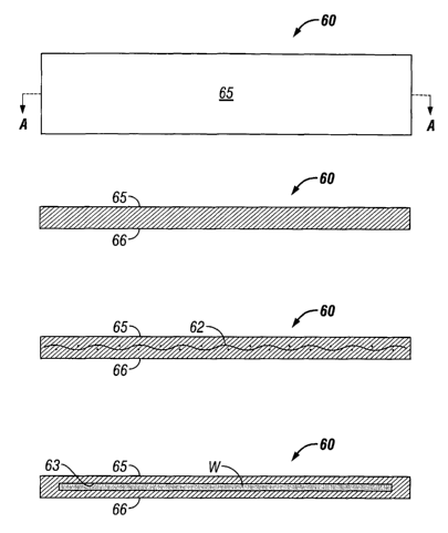
Referring initially in detail to FIG. 1, a support structure 60 in accordance
with
the present disclosure intended for use with a linear stapler has a generally
rectangular
shape and is made of a hydrophilic biomaterial. The support strip 60 includes
first
surface 65 and second surface 66, one of which will be in contact with the
tissue being
stapled, depending on whether the strip 60 is adhered to the staple cartridge
or the anvil
of the stapling apparatus. As seen in Fig. 1 A, the support structure 60 has a
generally
rectangular cross-section.
Turning now to FIGS. 2-4, support structures in the form of a strip in
accordance
with the present disclosure are shown generally as 60, 61. End 35 of surgical
stapling
device 20 has a first and a second tissue clamping member movable between an
open
position for receiving tissue therebetween, and a closed position for stapling
tissue
therebetween. The first tissue clamping member has a removable staple
cartridge 45
mounted therein. The second tissue clamping member is a moveable anvi140,
which is
opposite to the first tissue clamping member. Staple cartridge 45 contains a
plurality of
staples 49 housed within. Moveable anvi140 moves from the open position of
FIG. 2 to a
8
CA 02576441 2007-02-07
WO 2006/023578 PCT/US2005/029280
closed position adjacent to the removable staple cartridge 45 (not shown).
During
operation of the stapler, the staples 49 are driven from the removable staple
cartridge 45,
through the buttress strips 60 and 61, and are formed into tight "B" shapes
(not shown)
against the anvil 40. The ejection of the staples 49 from the removable staple
cartridge
45 also releases the second buttress strip 61 from the second tissue clamping
surface 41
and forms the "U" shaped staples 49 into "B" shapes. The "U" shaped staples 49
are
formed into "B" shapes by driving them through the second buttress strip 61
attached to
the second tissue clamping surface 41 and against the staple pockets 42 within
the anvil
40. As the wire of the staple 49 is driven into the staple pocket 42, the ends
of the staple
wire curl around into the "B" shape, and dislodge the support structure 60
from cartridge
45 and also detaches support structure 61 from the anvi140. The surgical
stapling device
and removable staple cartridge 45 are generally well known and described, for
example, in U.S. Pat. Nos. 4,354,628, 5,014,899 and 5,040,715.
In other embodiments, the support structure 100 made in accordance with this
15 disclosure can have a ring-like structure as shown in FIG. 5 and is
intended for use in
combination with an annular stapler, such as the type commonly employed for
performing anastomoses. In cross section, support structure 100 can have a
generally
rectangular configuration as seen in FIG 5A, or may have a tapered cross
sectional shape
as seen in FIG 5B.
20 Referring initially in detail to FIG. 6, a surgical stapling support
structure in the
form of a ring, in accordance with an embodiment of the present disclosure, is
generally
shown as 100. Ring 100 includes an annular ring 102 defined by an outer
terminal edge
104, an inner terminal edge 106, an upper surface 108 and a lower surface 110.
Inner
9
CA 02576441 2007-02-07
WO 2006/023578 PCT/US2005/029280
terminal edge 106 of ring 100 defines a central opening 112. One of upper
surface 108 or
lower surface 110 will be in contact with the tissue being stapled, depending
on whether
the ring 100 is adhered to the staple cartridge or the anvil of the stapling
apparatus.
As seen in FIG. 6, ring 100 cooperates with a circular stapling apparatus 10.
Stapling apparatus 10 includes an elongated neck 12 having a staple cartridge
assembly
14 operatively coupled to an end thereof and an anvil assembly 16 configured
and
adapted to removably engage the distal end of staple cartridge assembly 14.
Staple
cartridge assembly 14 is configured and adapted to expel an annular array of
staples (not
shown) out of the distal end thereof. Preferably, staple cartridge assembly 14
includes a
plurality of annular rows of staple slots 18 having staples therein. Anvil
assembly 16
includes a shaft 22 which is adapted to be releasably mounted within staple
cartridge
assembly 14 and an anvil 24 which is mounted on shaft 22 and is oriented to be
positioned towards the distal end of staple cartridge assembly 14. Anvi124 is
provided
with an annular array of staple forming cups 19, conforming to the number of
annular
rows and number of staple slots 18, the cups being configured and adapted to
form
staples, e.g. into a B-shape, as they are expelled from staple cartridge
assembly 14.
Ring 100 is releasably attached to either anvil assembly 16 or staple
cartridge
assembly 14. Alternatively, anvil assembly 16 and staple cartridge assembly 14
can both
have a reinforcing ring 100 disposed thereon (not shown) to provide a
tissue/support
"sandwich" upon actuation and/or firing of stapling apparatus 10.
The attachment of ring 100, to circular stapling apparatus 10 should be secure
enough to prevent ring 100 from slipping off of stapling apparatus 10, yet not
be so
strong as to inhibit separation of reinforcing ring 100 from stapling device
10 after
CA 02576441 2007-02-07
WO 2006/023578 PCT/US2005/029280
stapling device 10 has been actuated. Such releasable attachment can
advantageously be
effected by employing a plurality of pins as described in commonly assigned
U.S. Patent
No. 5,542,594, the entire contents of which are incorporated herein by
reference. It is
further contemplated that an adhesive, for example, a releasable adhesive, can
be
employed to achieve releasable attachment. Alternatively, a plurality of
longitudinally
spaced clips (not shown herein) may also be employed as the means for securing
ring 100
to stapling apparatus 10. The precise number and location of pins and/or clips
or the
amount or placement of continuity of spots or lines of adhesive is not
critical so long as
ring 100 is releasably attached to stapling apparatus 10. It should, of course
be
understood that the hydrophilic polymer chosen to make the support structure
advantageously can have a certain degree of adhesive properties, thus avoiding
the need
for any supplemental attachment means.
It is contemplated that a fibrous reinforcing element,such as a surgical grade
mesh, can be incorporated into the support structures in accordance with the
present
disclosure. For example, in FIG. 1B, strip 60 is shown to include mesh 62
therein, and in
FIG 5C, ring 100 is shown to include mesh 162 therein. Suitable fibrous
reinforcing
elements can be made from a biocompatible non-absorbable (i.e., permanent)
material,
such as, for example "TEFLON" which is a registered trademark owned by DuPont
de
Nemours & Co., or a biocompatible absorbable material. The biocompatible
materials
can be woven, knit or non-woven. Bio-absorbable materials include those
fabricated
from homopolymers, copolymers or blends obtained from one or more monomers
selected from the group consisting of glycolide, glycolic acid, lactide,
lactic acid, p-
dioxanone, a-caprolactone and trimethylene carbonate. Non-absorbable materials
11
CA 02576441 2007-02-07
WO 2006/023578 PCT/US2005/029280
include those that are fabricated from such polymers as polyethylene,
polypropylene,
nylon, polyethylene terephthalate, polytetrafluoroethylene, polyvinylidene
fluoride, and
the like. Further non-absorbable materials include and are not limited to
stainless steel,
titanium and the like.
In an alternative embodiment of a support structure in accordance with the
present
disclosure, a reservoir is provided which retains an amount of a biological
adhesive or
other useful substance therein. For example, as seen in FIG. 1 C, strip 60
includes
reservoir 63. As another example, as seen in FIG. 5D, ring 100 includes
reservoir 163.
While a biological adhesive has been disclosed as being retained within the
reservoir, it is
envisioned that reservoir can retain any type of wound closure material "W"
therein. It is
envisioned that wound closure material "W" can include one or a combination of
adhesives, hemostats, and sealants. Surgical biocompatible wound closure
materials
which can be retained in the reservoir include adhesives whose function is to
attach or
hold organs, tissues or structures, sealants to prevent fluid leakage, and
hemostats to halt
or prevent bleeding. Examples of adhesives which can be employed include
protein
derived, aldehyde-based adhesive materials, for example, the commercially
available
albumin/glutaraldehyde materials sold under the trade designation BioGlueTM by
Cryolife, Inc., and cyanoacrylate-based materials sold under the trade
designations
IndermilTM and Derma BondTM by Tyco Healthcare Group, LP and Ethicon
Endosurgery,
Inc., respectively. Examples of sealants, which can be employed, include
fibrin sealants
and collagen-based and synthetic polymer-based tissue sealants. Examples of
commercially available sealants are synthetic polyethylene glycol-based,
hydrogel
materials sold under the trade designation CoSea1TM by Cohesion Technologies
and
12
CA 02576441 2007-02-07
WO 2006/023578 PCT/US2005/029280
Baxter International, Inc. Examples of hemostat materials, which can be
employed,
include fibrin-based, collagen-based, oxidized regenerated cellulose-based and
gelatin-
based topical hemostats. Examples of commercially available hemostat materials
are
fibrinogen-thrombin combination materials under sold the trade designations
CoStasisTM
by Tyco Healthcare Group, LP, and TisseelTM sold by Baxter International, Inc.
Hemostats herein include astringents, e.g., aluminum sulfate, and coagulants.
While the above disclosure has related generally to two specific types of
stapling
apparatus, it should be understood that the support structures according to
the present
disclosure can be utilized in connection with any type of stapling apparatus
and the
stapling of any type of tissue. Further while the support structure has been
disclosed
herein in connection with certain embodiments and certain structural and
procedural
details, it is clear that changes, modifications or equivalents can be used by
those skilled
in the art. Therefore, the above description should not be construed as
limiting, but
merely as exemplifications of preferred embodiments. Those skilled in the art
will
envision other modifications within the scope and spirit of the present
disclosure.
13