Note: Descriptions are shown in the official language in which they were submitted.
CA 02576855 2007-02-09
WO 2006/020872 PCT/US2005/028747
HYDRAULIC LIQUID PUMPING SYSTEM
FIELD OF THE INVENTION
[0001] The present invention relates to a liquid pumping system, and more
particularly to a liquid pumping system that utilizes liquid to compress a gas
and uses a part
of the compressed gas to recycle the liquid within the system.
BACKGROUND INFORMATION
[0002] Many liquid pumping systems have means for entrapping and compressing
air in order to generate rotational mechanical energy. However, most
traditional designs
required a naturally occurring steep vertical fall that is fed by a stream of
water, such as a
waterfall, in order to be operational. This required that the water source
must be located on
ground having a high altitude and the compressed gas accumulator must be
located on ground
having a lower altitude. In conventional systems, water expelled from the
system is returned
to the moving water source at a return location that is different from the
location that feeds
the system, i.e., the water return point has a lower altitude than the point
where water is taken
from the stream to fill the conventional system. These geographic constraints
drastically
limited the areas that many hydraulic air compressor systems could be located.
Furthermore,
water passing through a traditional liquid pumping system could be used only
once, thereby
requiring a continuous renewable resource of liquid to drive the system.
Accordingly, a need
remains for a liquid pumping system that uses compressed gas to drive a
mechanical device
that does not require a continuous renewable water source. The present
invention has been
developed in view of the foregoing.
SUMMARY OF THE INVENTION
[0003] An aspect of the present invention is to provide a system comprising a
body
of liquid, a down pipe in fluid communication with the body of liquid, a gas
injection
apparatus for introducing gas into the liquid that passes through the down
pipe, wherein the
down pipe and the gas injection apparatus are structured and arranged to
compress the gas, a
separator for separating compressed gas from the liquid, and a gas-liquid
recycle loop. The
gas-liquid recycle loop comprises a compressed gas storage vessel containing
the separated
gas, a reservoir containing liquid separated from the compressed gas, and a
gas-liquid pump
-1-
CA 02576855 2007-02-09
WO 2006/020872 PCT/US2005/028747
having a gas inlet in communication with the gas storage vessel, and a fluid
inlet in
communication with the reservoir, the gas-liquid pump structured and arranged
for pumping
the liquid to the body of liquid and delivering the gas to the gas injection
apparatus.
[0004] Another aspect of the present invention is to provide a system
comprising a
body of liquid, a down pipe in fluid communication with the body of liquid,
means for
introducing gas into the liquid, the down pipe and the means for introducing
gas into the
liquid structured and arranged to compress the gas, means for separating the
compressed gas
from the liquid, means for recycling the separated gas back to the means for
introducing gas
into the liquid, and means for recycling the liquid separated from the
compressed gas back to
the body of liquid.
[0005] A further aspect of the present invention is to provide a method
comprising
the steps of providing a body of liquid, providing a down pipe in fluid
communication with
the body of liquid, introducing gas from a gas injection apparatus into the
liquid that passes
through the down pipe to produce a compressed gas, separating the compressed
gas from the
liquid, and recycling the separated gas and liquid. The step of recycling the
separated gas and
liquid comprising the steps of storing the compressed gas in a gas storage
area, storing the
liquid separated from the compressed gas in a reservoir, introducing the
compressed gas from
the gas storage area and the liquid from the reservoir into a gas-liquid pump,
pumping the
liquid to the body of liquid, and delivering the gas to the gas injection
apparatus.
[0006] These and other aspects of the present invention will be more apparent
from
the following description.
BRIEF DESCRIPTION OF THE DRAWING
[0007] Fig. 1 is a schematic representation of a first loop gas-liquid pumping
system
in accordance with an embodiment of the present invention.
[0008] Fig. 2 is a schematic representation of a first loop gas-liquid pumping
system
having a first angled section and a second angled section and a gas injection
apparatus in
accordance with an embodiment of the present invention.
[0009] Fig. 3 is a schematic representation of a first loop gas-liquid pumping
system
including a siphon pump in accordance with an embodiment of the present
invention.
[0010] Fig. 4 is a schematic representation of a multiple first loop gas-
liquid
pumping system in accordance with an embodiment of the present invention.
-2-
CA 02576855 2007-02-09
WO 2006/020872 PCT/US2005/028747
[0011] Fig. 5 is a schematic representation of a first loop and second loop
gas-liquid
pumping system in accordance with an embodiment of the present invention.
[0012] Fig. 6 is a schematic representation of a first loop and second loop
gas-liquid
pumping system comprising a turbine in the first loop system in accordance
with an
embodiment of the present invention.
DETAILED DESCRIPTION
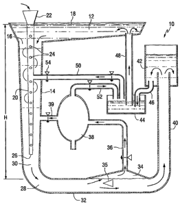
[0013] As shown in Fig. 1, a first loop system 10 of the present invention
comprises
a source liquid area 12. Source liquid area 12 can comprise a vessel suitable
for housing a
body of water, such as a holding tank, clay lined pond, reservoir and the
like, or a region
within a body of liquid, such as a river, stream, and the like. Source liquid
area 12 can
comprise any suitable liquid, such as water, and can have any desired volume,
depending on
the needs of the first loop system 10. In one embodiment, the first loop
system 10 can be
oriented substantially below the source liquid area 12, such as oriented
underground, below a
lake or body of open water.
[0014] A down pipe 14 structured to receive liquid from the source liquid area
12 can
be positioned within the source liquid area 12. The down pipe 14 is
substantially aligned in
the vertical direction and can include a pipe opening 16 that is at least
partially recessed
below the surface of the liquid 18. The down pipe 14 can comprise any suitable
piping
material, such as plastics and/or metals that are corrosion resistant. The
down pipe 14 can
have any suitable height H, such as from about 8 feet to about 1,000 feet or
more. In another
embodiment, the down pipe 14 can have any suitable height H of from about 10
feet to more
than about 2,000 feet. The down pipe 14 can have any suitable diameter, such
as from about
2 inches to about 100 feet. In another embodiment, a down pipe 14 having a
height H of
about 350 feet can have a diameter of from about 8 feet to about 40 feet,
depending on flow
requirements within the system. In one embodiment, the down pipe 14 can be
uniform in
diameter or can have an inward taper at a lower vertical position of the down
pipe 14. In one
embodiment, the down pipe 14 can have an area at a lower vertical end position
that is from
about 10 percent to about 95 percent the area of the down pipe 14 at a higher
vertical end
position. In another embodiment, the down pipe 14 can have an area at a lower
vertical end
position that is from about 40 percent to about 60 percent the area at a
higher vertical end
position.
-3-
CA 02576855 2007-02-09
WO 2006/020872 PCT/US2005/028747
[0015] A gas injection apparatus, such as a gas entrainment tube 20, can be at
least
partially positioned within the down pipe 14. In one embodiment, the gas
entrainment tube
20 is at least partially circumferentially disposed within the interior of the
down pipe 14. The
gas entrainment tube 20 can have a gas receiving port 22 that extends at least
partially above
the surface of the liquid 18. The gas receiving port 22 can receive air from
the atmosphere,
gas from a tank source, or gas blown in by a fan. Conventional gas directing
means, such as
fans, blowers, ducts, and the like can be used to direct gas into the gas
receiving port 22. In
one embodiment, the gas can be heated to a temperature exceeding the ambient
temperature
by any conventional heating means, such as burners, flame reactors and the
like.
[0016] The gas entrainment tube 20 can comprise a plurality of gas access
ports 24
extending through a sidewall of the gas entrainment tube 20. In one
embodiment, the gas
entrainment tube 20 can have a vertical height that extends substantially the
entire vertical
height of the down pipe 14. In another embodiment, the gas entrainment tube 20
can have a
vertical height that extends from about 50 percent to about 80 percent the
vertical height of
the down pipe 14. The gas entrainment tube 20 can have any suitable dimensions
such that
the outer diameter of the gas entrainment tube 20 is smaller than the inner
diameter of the
down pipe 14. In one embodiment, the gas entrainment tube 20 can have an outer
diameter
that is about 50 percent the inner diameter of the down pipe 14. In another
embodiment, the
gas entrainment tube 20 can have at an inward taper corresponding to an inward
taper of the
down pipe 14.
[0017] The down pipe 14 and the gas entrainment tube 20 can be made from any
suitable material sufficient to resist the compressive forces of the contained
liquid and gas,
such as metal and/or plastic. In one embodiment, the down pipe 14 and the gas
entrainment
tube 20 are made from a substantially corrosion-resistant material. As the
amount of gas
present in the down pipe 14 increases, the velocity of the liquid can be
retarded by the upward
movement of gas bubbles in the down pipe 14. Smaller bubbles of gas tend to
provide less
liquid velocity retardation within the down pipe 14. Accordingly, in one
embodiment, means
for introducing smaller bubbles of gas into the down pipe 14 can include small
holes, having
a diameter such as from less than 0.25 inches to about 3 inches, extending
through the
sidewalls of the gas entrainment tube 20, fine bubble meshes, and gas metering
means for
limiting the flow of gas into the gas entrainment tube 20 at any specified
time.
[0018] In one embodiment, liquid from the source liquid area 12 is directed
into the
-4-
CA 02576855 2007-02-09
WO 2006/020872 PCT/US2005/028747
down pipe 14 and gas is simultaneously introduced into the gas entrainment
tube 20. In
another embodiment, liquid from the source liquid area 12 is directed into the
down pipe 14
and gas is subsequently introduced into the gas entrainment tube 20. In one
embodiment, gas
contained within the gas entrainment tube 20 is directed through the gas
access ports 24 and
combines with the liquid traveling within the down pipe 14.
[0019] As the liquid travels vertically downward in the down pipe 14 and the
gas is
forced vertically downward in the gas entrainment tube 20 and out from the gas
entrainment
tube 20 into the down pipe 14 through gas access ports 24, the gas and liquid
mix together to
form a gas-liquid mixture. The down pipe 14 can be attached, in fluid-gaseous
communication, to an angled pipe section 28 at the lower end 30 of the down
pipe 14. The
angled pipe section 28 can have an angle of from about 70 to about 100 . In
another
embodiment, the angled pipe section 28 can have an angle of about 90 . The
angled pipe
section 28 can comprise a single angled section or multiple angled sections
that result in an
angle of from about 70 to about 100 , such as about 90 . The use of multiple
angled
sections can reduce the wear on the piping joint connecting the angled pipe
section 28and the
down pipe 14 by more evenly distributing the water pressure from the down pipe
14 across
several angled sections, each having a smaller angle.
[0020] The angled pipe section 28 can be connected, in fluid-gaseous
communication, to a bottom tube 32. In one embodiment, the bottorri tube 32 is
oriented
substantially perpendicular to the orientation of the down pipe 14. The bottom
tube 32 can
comprise a pipe having a diameter that is substantially the same size as the
diameter of the
lower end of the down pipe 14. In another embodiment, the cross-sectional area
of the
bottom tube 32 is substantially equivalent to the difference in the cross-
sectional area between
the down pipe 14 and the gas entrainment tube 20. In one embodiment, the
angled pipe
section 28 can comprise a chamber that allows for the collection of gas from
the gas-liquid
mixture and allows liquid to flow through to a bottom tube 32.
[0021] In another embodiment, as shown in Fig. 2, the down pipe 14 and angled
pipe
section 28 can be configured to comprise a'first angled section 28a having a
radius of
curvature A of from 15 to 60 and a second angled section 28b having a radius
of curvature
B of from about 5 to about 45 . A second gas injection apparatus, such as a
gas blower 29,
can be connected to a pipe 31 which can pass through port 33 that extends into
the angled
pipe section 28a and 28b. The gas blower 29 can inject gas into the angled
section 28a and
-5-
CA 02576855 2007-02-09
WO 2006/020872 PCT/US2005/028747
28b in an upwardly angled direction, such as at about a 45 angle. A benefit
to including a
gas blower 29 in the angled section 28 is that the gas is added in
substantially the same
direction as the liquid flow. As the gas bubbles follow their natural tendency
to rise, the
bubbles are directed with the liquid flow. When gas is applied such as along
the gas
entrainment tube 20, the natural tendency for the gas bubbles to rise retards
the downward
liquid velocity in the down pipe 14. By introducing gas into the system at an
angle, such as
an angle corresponding to the first angled section 28a, the direction of the
gas bubbles rising
is additive to the direction of the liquid velocity. The gas blower 29 can be
used in
conjunction with the gas entrainment pipe 20 as a means of increasing the
volume of gas
present in the first loop 10. In one embodiment, the gas blower 29 can be used
as a complete
replacement for the gas entrainment tube 20. In another embodiment, the gas
blower can
receive compressed air from the compressed air storage tank 38.
[0022] As shown in Figs. 1 and 2, the bottom tube 32 can be constructed to
have an
area of increased volume that allows gas to separate from the liquid as the
gas-liquid mixture
flows through the bottom tube 32. The area of increased volume can comprise a
gas reservoir
34. In one embodiment, bottom tube 32 is flared to form a gas reservoir 34. In
another
embodiment, bottom tube 32 transitions directly into a gas reservoir 34. The
gas reservoir 34
can comprise any suitable volume and dimensions, such as from about 2 to about
20 times the
square area of the bottom tube 32.
[0023] The gas reservoir 34 can be integrally formed with the bottom tube 32
or can
comprise a separate chamber connected to the bottom tube 32 in gaseous
communication with
the gas contained in gas-liquid mixture in the bottom tube 32. The gas
reservoir 34 can be
positioned at least partially above the bottom tube 34 to allow gas from the
gas-liquid mixture
to rise above, and be concentrated from, the liquid phase of the gas-liquid
mixture. In one
embodiment, from up to about 8 ft.3 of air, such as from about 0.5 ft.3 to
about 4 ft.3 of air,
can be separated from water given a flow in the down pipe 14 of 1 ft.3 per
minute.
[0024] As the gas-liquid mixture flows through the bottom tube 32 and into the
area
of increased volume, the gas phase of the gas-liquid mixture escapes to the
lower pressure
zone in the gas reservoir 34. At the same time, the liquid phase of the gas-
liquid mixture
remains in the bottom tube 32 and flows through the remainder of the bottom
tube 32. In one
embodiment, a liquid breaker 35 can be positioned within the bottom tube 32
prior to the gas
reservoir 34 in order to allow greater separation of the gaseous phase from
the liquid phase of
-6-
CA 02576855 2007-02-09
WO 2006/020872 PCT/US2005/028747
the gas-liquid mixture contained in bottom tube 32. The liquid breaker 35 can
comprise any
suitable material such as metal and/or plastic mesh or solid structures. In
one embodiment,
the liquid breaker 35 can comprise a triangular, conical or circular shape.
The liquid breaker
can comprise any suitable dimensions such as from about 20 percent to about
100 percent of
the cross-sectional area of the bottom tube 32.
[0025] Gas collected in the gas reservoir 34 can be extracted through a pipe
36 and
diverted into a compressed gas storage tank 38 in which the gas can be stored.
The pipe 36
may comprise at least one flow regulation device, such as a one-way valve,
pressure gauge,
and the like. The compressed gas storage tank 38 can be any suitable gas
storage tank and
can have any suitable volume and dimensions. In one embodiment the compressed
gas
storage tank 38 can contain at least 100 times the volume of the gas contained
in gas reservoir
34. In one embodiment, at least some gas from the gas storage tank 38 can be
discharged
back into the system, either directly into the gas entrainment tube 20 or into
the down pipe 14
through pipe 39. Pipe 39 can be optionally fitted with valve means to prevent
the back flow
of liquid through pipe 39 and into the gas storage tank 38.
[0026] The liquid phase separated from the gas-liquid mixture in bottom tube
32
subsequently flows through a discharge pipe 40 into a secondary reservoir 42.
The secondary
reservoir 42 can comprise any suitable storage tank having a volume selected
by the user
according to the volume flow requirements of the system 10. In one embodiment,
the
secondary reservoir 42 has a volume capable of holding from about 3 to about
10 times the
liquid flow of the liquid in the discharge pipe 40 per minute at a rate
specified by the design
of the system.
[0027] In one embodiment, the secondary reservoir 42 is positioned at a
vertical
height of from about 30 to about 98 percent of the height H of the down pipe
14. In another
embodiment, the secondary reservoir 42 is positioned at a height of from about
75 to about 85
percent the height H of the down pipe 14. In one embodiment, the force of the
liquid entering
the bottom pipe 32 is sufficient to direct the liquid through the discharge
pipe 40 in a
substantially vertical direction to a height of from about 30 to about 98
percent, such as about
80 percent, of the height H of the down pipe 14. The height of the discharge
pipe 40 can be
selected to control the gas pressure output into the compressed gas storage
tank 38 of the
system. In one embodiment, a plurality of discharge pipes 40 in flow
communication with
each other can be used to allow liquid to flow from the bottom 32 to the
secondary reservoir
-7-
CA 02576855 2007-02-09
WO 2006/020872 PCT/US2005/028747
42. In another embodiment, the square area of the cross-section of the
discharge pipe 40 is
about twice the square area of the cross-section of the bottom tube 32.
[0028] Gas from the compressed gas storage tank 38 and liquid from the
secondary
reservoir 42 can be directed to a tank 44 containing a compressed gas-liquid
pump during the
gas-liquid moving system. In one embodiment, the compressed gas-liquid pump
can be a
bladder pump or siphon pump as will be described herein. In one embodiment,
the tank 44
has a vertical orientation that is lower than the secondary reservoir 42,
thereby allowing tank
44 to be at least partially gravity fed by the secondary reservoir 42. Liquid
from the
secondary reservoir 42 can be directed to the tank 44 through a pipe 46. The
pipe 46 can
comprise any suitable conventionally known monitoring devices and/or
restrictive flow-back
devices. The volume of liquid flow in to and out of tank 44 must equal or
slightly exceed the
volume of liquid flow in down pipe 14.
[0029] In one embodiment, the compressed gas-liquid pump contained in tank 44
can
be connected to two liquid pipes 46 and 48 and two gas pipes 50 and 52
extending out from
the tank 44. The liquid output of the pump can be raised in the vertical
direction through pipe
48 and returned to the height of the source liquid area 12. In order to pump
liquid to this
level, gas having a desired volume and pressure is directed from the
compressed gas storage
tank 38 along pip'e 52 into tank 44 housing the compressed gas-liquid pump.
[0030] The required psi of gas contained in the compressed gas storage tank 38
can
be determined for a system using air and water according to Equation 1, in
which 1 ft.3 of
water weighs 62.41bs, and the pressure per inch2 of the water is (62.4
lbs./in.2 )/(144 in.2 ) or
0.433 lbs./in.'.
Equation 1: 20 ft. x .433 psi/ft. = 8.66 psi.
Accordingly, the pressure required to lift the liquid must exceed the value
determined by
Equation 1. Thus, 1 ft.3 of air at about 9 psi would lift 1 ft.3 of water
about 20 feet.
[0031] In one embodiment, only a portion of the compressed gas housed in the
compressed gas storage tank 38 is directed along pipe 52. Valve means or other
regulatory
means can be included in pipe 52 to control the flow of gas from compressed
air storage tank
38. The amount of gas and timing of the release of gas from the compressed gas
storage tank
38 can be controlled via electric timed valves, mechanical valves and/or
computer controlled
-8-
CA 02576855 2007-02-09
WO 2006/020872 PCT/US2005/028747
valves. As the volume of compressed gas increases in the tank 44, the liquid
housed in tank
44 is forced up pipe 48. In one embodiment, liquid flow back through pipe 48
can be limited
by a one-way valve or series of valves. In another embodiment, the pressure of
the
compressed gas is sufficient to move the liquid in pipe 48 in a substantially
vertical direction.
In another embodiment, the pressure of the compressed gas is sufficient to
move the liquid in
pipe 48 from a liquid level below the secondary reservoir 42 to the liquid
level 18 in the
source liquid area 12.
[0032] Once a measured volume of compressed gas is injected into tank 44, pipe
52
can be closed by any suitable valve means to stop the upward movement of
liquid in pipe 48.
The pipe 50 can then be opened to remove at least some compressed gas in tank
44. In one
embodiment, pipe 50 can be connected to the down pipe 14. The liquid flow down
the down
pipe 14 can create a lower pressure area at the joint between the pipe 50 and
the down pipe
14. The higher pressure gas from tank 44 can be quickly drawn to this area of
lower pressure.
The joint between the pipe 50 and the down pipe 14 can comprise a valve
suitable for
allowing gas to pass from pipe 50 and preventing liquid to pass from the down
pipe 14 to the
pipe 50. The higher pressure gas exiting the compressed gas-liquid pump housed
in tank 44
and flowing through the pipe 50 can be recycled into the down pipe 14 to
create a higher
pressure compressed air to water flow ratio. Gas contained in pipe 50 can be
directed directly
into the gas entrainment tube 20, into the gas receiving port 22, or into the
down pipe 14 at
any vertical location provided the exit pressure is sufficiently controlled,
such as by valve
means, to prevent the flow of liquid in an upward direction in the down tube
14.
[0033] As the pipe 50 is opened, the pressure in tank 44 decreases. In one
embodiment, a one-way valve in pipe 46 can be opened to allow liquid from the
secondary
reservoir 42 to flow into tank 44 and fill the space previously occupied by
the compressed gas
in the tank 44. Once the tank 44 is re-filled with liquid from the secondary
reservoir, the gas-
liquid moving system can be repeated.
[0034] Once the liquid in tank 44 has been moved to a desired level through
pipe 48,
the gas present in tank 44 must be removed in order to refill tank 44 with
liquid for a second
pumping cycle. The gas exits tank 44 at the pressure required to move the
liquid vertically
through pipe 48, which is greater than the pressure of the liquid falling in
down pipe 14. The
gas can be removed from the tank 44 along pipe 50 and injected back into the
falling liquid
steam of down pipe 14. The suction draw of the liquid flowing down the down
pipe 1 can
-9-
CA 02576855 2007-02-09
WO 2006/020872 PCT/US2005/028747
increase the exit speed of the gas from the gas-liquid pump in tank 44 along
pipe 50.
[0035] In one embodiment, as described above, the compressed gas-liquid pump
can
be a bladder pump. In this embodiment, the pipe 52 can be connected to a
flexible bladder
that can expand to force liquid through tube 48. The bladder can comprise any
flexible
material, including polymeric material and coated textiles. The bladder pump
can provide a
defined barrier between the compressed gas and the liquid, thereby preventing
the compressed
gas from traveling back into the liquid at the liquid-air interface within the
pump.
[0036] In another embodiment, as shown in Fig. 3, the compressed gas-liquid
air
pump can be a siphon pump. A siphon pump can typically be used when the
distance the
liquid is forced in a substantially vertical direction is less than about 30
feet. Typically, a
siphon pump can be used when the vertical distance the liquid is forced is
from about 1 inch
to about 25 feet. It is anticipated that any conventional siphon pump can be
used in
accordance with the present invention.
[0037] As shown in Fig. 3, the siphon pump 58 can be connected between the
secondary reservoir 42 and an area at or above the liquid level 18 in the
source liquid area 12.
The siphon pump 58 can be located at least about 1 foot above the liquid level
18 of the
source liquid area 12, or greater. A pipe 60 can be at least partially
submerged in the
secondary reservoir 42 and extend substantially vertically into the siphon
pump 58. The pipe
60 can comprise valve means, such as one-way valves, to prohibit liquid from
falling back
into the secondary reservoir 42. In one embodiment, a gas pipe 62 having
suction means, can
be connected at about the top of the siphon pump 58. The gas pipe 62 can
remove gas from
the siphon pump 58 and direct the gas into the gas receiving port 22 for
entrainment with the
falling liquid in down pipe 14.
[0038] When the siphon pump 58 is full of liquid from the secondary reservoir
42,
the gas pipe can be shut off using any conventional valve means and a second
gas pipe 64 can
be opened to allow additional gas from atmosphere or a tank source to enter
the siphon pump
58. As the gas enters the siphon pump 58, the liquid flows out the siphon pump
58. In one
embodiment, liquid is returned to the source liquid area 12 through a pipe 66.
In another
embodiment, liquid can be distributed through pipe 66 for land irrigation
purposes. The pipe
66 can comprise valve means, such as one-way valves, to prohibit liquid from
flowing if
desired. Due to the slower nature of siphon pumping, two siphon pumps could be
used
working in opposite phases of charge/discharge. This design could allow the
liquid to gain
-10-
CA 02576855 2007-02-09
WO 2006/020872 PCT/US2005/028747
velocity before the gas is introduced into the first loop system 10. In one
embodiment, use of
the siphon pump 58 eliminates the need for pipe 50.
[0039] When sufficient pressure and volume are established in the tank 44
housing
the compressed gas-liquid pump to move the liquid in a vertical distance to
the source liquid
area 12, no external compressed gas is required. Any gas collected in the
compressed gas
storage area 38, not required to move the liquid in the vertical direction
within the first loop
system 10, is "excess gas".
[0040] As shown in Fig. 4, it is contemplated herein that a plurality of first
loop
systems can be combined and connected to further increase the pressure of the
compressed
gas. The first stage of first loop system 100 is provided as described above.
A first source
liquid area 112 can be a closed body of liquid, such as a tank, or an open
body of liquid.
Liquid travels downwards along the down pipe 114 and gas is introduced through
gas
receiving port 122 into gas entrainment tube 120. The gas and liquid mix
together in the
down pipe 14 and flow together into the bottom tube 132. The gas is separated
in the gas
reservoir 134 and directed through pipe 136 into a first compressed gas
storage tank 138. The
pressure P1 of the gas contained within the first compressed gas storage tank
138 is equal to
0.433 psi multiplied by the height H1 of the discharge pipe 140. The remaining
components
of the first stage of the first loop system 100 function as described above.
[0041] In order to increase the gas pressure of the first stage of the first
loop system
100, a second stage of the first loop system 200 is added to take the
pressurized gas from the
first compressed gas storage tank 138 and direct the gas to a second stage of
first loop system
200. The second stage of the first loop system 200 is fully enclosed to
maintain the pressure
P1 from the first compressed gas storage tank 138 including the source liquid
area 212 and
the secondary reservoir 242. By enclosing all of the components, the pressure
generated from
the first stage of the first loop system is maintained.
[0042] In this embodiment, at least a portion of the gas housed within the
first
compressed gas storage tank 138 is directed to a second gas receiving port 222
of the second
stage of the first loop system 200 through pipe 180. A second down pipe 214
receives liquid
from the enclosed second source liquid area 212 and the gas introduced into
the second gas
receiving port 222 and the liquid mix together in the second down pipe 214 and
flow together
into the second bottom tube 232. The gas is separated in the second gas
reservoir 234 and is
directed through pipe 236 into a second compressed gas storage tank 238. The
remaining
-11-
CA 02576855 2007-02-09
WO 2006/020872 PCT/US2005/028747
components of the second stage of the first loop system 200 function as
described above.
[0043] The second stage of the first loop system 200 can be configured in the
same
manner as described herein, however, due to the increased gas pressure
provided from the
first compressed gas storage tank 138 to the second stage of the first loop
system, a higher
pressure P2, less any inefficiencies, can be achieved in the second compressed
gas storage
tank 238. The pressure P2 achieved in the second compressed gas storage tank
138 is
determined according to Equation 2, where P1 is the pressure achieved in the
first compressed
gas storage tank 138, and H2 is the height of the second discharge pipe 240:
Equation 2: P2 = P1 + 0.433 psi x H2
[0044] As shown in Fig. 5, the compressed gas generated by the first loop
system(s)
100 and/or 200 shown in Figs. 1-4 can be introduced into a second loop system
400. In one
embodiment, the second loop system 400 can be positioned above ground and the
first system
100 can be positioned at least partially underground. In another embodiment,
the second loop
system 400 can be positioned at any desired location adjacent the first system
100. The
components of the second loop system 400 are all enclosed thereby making a
closed loop
system and preserving the input pressure from the first loop system. In this
embodiment, a
first loop system is initiated as described above. Liquid from a source liquid
area 412 travels
downwards along the down pipe 414 and gas is introduced through gas receiving
port 422
into gas entrainment tube 420. The gas and liquid mix together in the down
pipe 414 and
flow together into the bottom tube 432. The gas is separated in the gas
reservoir 434 and
directed through pipe 436 into a compressed gas storage tank 438. The
remaining
components of the first loop system function as described above.
[0045] At least a portion of the compressed gas from the compressed gas
storage tank
438 is directed to the second loop system 400 by pipe 480. Pipe 480 provides
compressed gas
to tank 450 housing a second compressed gas-liquid pump. In one embodiment the
,
compressed gas-liquid pump can be a bladder pump. Valve means or other
regulatory means
can be included in pipe 480 to control the flow of gas from the compressed gas
storage tank
438. In another embodiment, the flow of gas from the compressed gas storage
tank 438 can
be controlled via a remote computer. As compressed gas from the compressed gas
storage
tank 438 is fed into the 450 tank containing the second compressed gas-liquid
pump, liquid in
-12-
CA 02576855 2007-02-09
WO 2006/020872 PCT/US2005/028747
the tank 450 can be forced substantially vertically through a pipe 452 to a
second body of
liquid 454 or other liquid return area. In one embodiment, the pressure of the
compressed gas
entering the tank 450 housing the second gas-liquid pump is sufficient to move
the liquid in
the tank 450 to a height of from about 40 to about 98 percent the height of
the discharge pipe
440 in the first loop system. If gas having 40 psi is separated from the
liquid in the gas
reservoir 434, then the second compressed gas-liquid pump housed in tank 450
could raise
liquid to an equilibrium maximum height of (40 psi/ft) divided by 0.433 from
Equation 1, to
reach a height of 92 ft.
[0046] In one embodiment, a return pipe 460 is provided in gas-flow
communication
with the second compressed gas liquid pump housed in tank 450. Once sufficient
pressure is
established in the tank 450 housing the compressed gas-liquid pump, any excess
gas can be
removed from the tank 450 through return pipe 460. The return pipe 460 can be
connected to
the down pipe 414 to allow the excess gas to be incorporated into the liquid
flowing
downward in the down pipe 414. By returning the compressed gas from the second
loop
system 400 after it has displaced the liquid in the tank 450 containing the
second compressed
gas-liquid pump to the down pipe 414, the resulting volume of compressed gas
is increased in
the first loop system. Any suitable valve means can be included in the return
pipe 460 to
allow gas to enter the down pipe 414 and prevent liquid in the down pipe 414
from entering
the return pipe 460.
[0047] The second compressed gas-liquid pump housed in tank 450 can function
in
the same manner as the first compressed gas-liquid pump shown in Figs. 1-3,
however, the
second compressed gas-liquid pump can pump at a higher pressure.
[0048] As shown in Fig. 5, the liquid forced up pipe 452 can be directed to a
second
body of liquid 454, such as a reservoir. Liquid collected in second body of
liquid 454 can be
directed to flow down a pipe 462 by gravitational forces. In one embodiment,
the down pipe
462 has a vertical height that is shorter than the vertical height of pipe
452. In one
embodiment, a hydropower generator 466 used to produce electricity can be
positioned within
pipe 462. In another embodiment, liquid discharged from the hydropower
generator 466 can
be discharged into an open tank 468 which can be subsequently used to provide
liquid to tank
450 housing the second compressed gas-liquid pump.
[0049] In another embodiment, as shown in Fig. 6, a conventional turbine 490
can be
positioned at the bottom of the down pipe 414. A rotating propeller of the
turbine could be
-13-
CA 02576855 2007-02-09
WO 2006/020872 PCT/US2005/028747
positioned in the down pipe 414 to separate the gas phase and the liquid phase
present in the
down pipe 414. In another embodiment, the turbine 490 can be positioned within
gas
reservoir 434 to reduce the back pressure applied to the turbine 490 as a
result of the liquid
velocity falling in the down pipe 14. In both embodiments, liquid falling
downwards in down
pipe 414 causes the propeller to spin. The rotating propeller of the turbine
can be connected
to a generator that can be used to produce electricity. As the propeller
rotates, it can power
any traditional hydroelectric generator. The electricity produced by the
generator could be in
addition to the power generated by the rotation of the hydropower generator
466 of the second
loop system 400.
[0050] The piping and containment vessels of the present invention can
comprise any
material, such as any polymeric material or any sufficiently durable metal.
The piping and
containment vessels of the present invention can be coated with a variety of
coatings
including corrosion resistance coatings. The dimensions of the system can be
selected in part
based on the density of the liquid to be pumped and the desired power output.
The power
produced as a result of the present invention can be used to power any device
or system
conventionally powered by coal, oil, natural gas or wood. In addition, the
power produced by
the present invention can be used to operate a hydrogen-producing system. The
generation of
power depends in part on the height of the down tube 1 and pipe 4 as will be
explained by the
following examples.
Example 1
[0051] A partial system set-up was constructed to demonstrate that a
relatively low
air pressure can be used to pump water in a system as described above at a
rate sufficient to
sustain the water-air hydraulic cycle. With the proper height ratio of down
pipe height to
discharge pipe height the system can return liquid to the starting point
within the system.
[0052] A first rack was positioned 234" above the ground and a source liquid
area
=tank having a 175-gallon volume was positioned on the first rack. The sides
of the source
liquid area tank were 14" high. Water was fed from the source liquid area tank
into a funnel
at the top of a down pipe comprising a 3" length of 4" diameter pipe connected
to a 4" length
of 3" diameter pipe connected to an 8" length of 2" diameter pipe connected to
a 1.5"
diameter plastic pipe having a length of 209". The total length of the down
pipe was 224".
Water was introduced to the funnel by a 2" right angle pipe connected to a
1.375" butterfly
-14-
CA 02576855 2007-02-09
WO 2006/020872 PCT/US2005/028747
valve extending out of the source liquid area tank.
[0053] The water flowed downwards in the down pipe into a 55-gallon drum air
separator turned on its side positioned on the ground. The air separator had a
2" cast iron
pipe welded to the side of the barrel. The cast iron pipe was oriented to
accept the 1.5"
diameter plastic down pipe and was connected by rubber grommets to prevent air
and water
leakage. The plastic down pipe extended 1" within the air separator. At the
end of the down
pipe a 1" plastic end cap was riveted with the rounded end being exposed to
the water stream
traveling downwards in the down pipe. A 1.5" gap was located between the end
of the down
pipe and the end cap. The end cap functioned to disperse the water and allow
the air trapped
in the down stream to escape from the water into the air separator. The water
exited the air
separator by a 2" horizontal plastic pipe positioned below the water level in
the air separator.
In order to visualize the water level, a sight glass was installed in the air
separator. The air
separator has a 1" air exit valve positioned near the top of the air separator
for extracting the
compressed air to maintain a constant water level in the air separator.
[0054] The exit bottom water pipe had a length of 7 feet and was bent upward
in a
90 angle into a discharge pipe having a height of 179". The top of the
discharge pipe was
connected with a right angle pipe and a 45 angle pipe so that exiting water
would flow into a
secondary reservoir positioned on a second rack having a height of 165.5"
above the ground.
The secondary reservoir was similar in size to the source liquid area tank.
Water from the
secondary reservoir flowed into the top of a 55-gallon barrel gas-liquid pump
positioned on a
third rack located 129" above the ground through a 2" ball valve. The valve
was used to shut
down the flow of water from the secondary reservoir into the air-water pump
when the unit
was not operating.
[0055] Under working conditions, the water flow into the air-water pump was
controlled by the air pressure present in the pump. If the air pressure was
below 1 psi, water
could flow into the air-water pump. Two air valves controlled by an electric
tether switch
were used to control the pressure within the pump. When a first valve was
opened, the
second valve was closed. During operation, compressed air from the air
separator was put
into the air-water pump and increased pressure within the pump. When the
pressure exceeded
4.1 psi, the water was pumped to the liquid source area tank. Water was
prevented from
returning to the secondary reservoir by a one-way check flow valve.
[0056] Once the water level dropped below a water level determined by the
tether
-15-
CA 02576855 2007-02-09
WO 2006/020872 PCT/US2005/028747
switch, the air valves reverse their position. The pressurized air at 4.1 psi
from the air water
pump was removed from the air-water pump and was available to recycle back
into the down
pipe to increase the compressed air output of the hydraulic air compressor.
Once the
compressed air exited the air-water pump, the air pressure returned to a level
below 1 psi and
the water from the secondary reservoir flowed into the air-water pump to
initiate a new cycle.
Water in the 2" discharge pipe from the air-water pump was prevented from
entering the air-
water pump by a directional flow valve.
[0057] The air exit valve from the air separator was connected to a 100-gallon
air
tank that served as a compressed air storage tank. Air collected in the
compressed air storage
tank was used to supply compressed air to the air-water pump for moving water
from the
secondary reservoir to the liquid source area tank. The amount of air
entrained by the system
was not sufficient to fully sustain the process.
Example 2
[0058] The second trial was made using the system of Example 1 with several
modifications. A clear plastic 2" diameter pipe was attached below the funnel.
Inside the 2"
pipe a 1" gas entrainment pipe with 0.125" holes drilled into the sides was
inserted. The gas
entrainment pipe was used to supply air to the stream of water traveling down
the down pipe.
The 1" plastic pipe had a 1.25" outer diameter and the area difference between
the 2" inner
diameter down pipe and the 1.25 outer diameter gas entrainment pipe was 1.914
in2. This
was slightly bigger than the area of a 1.5" inner diameter pipe (1.76 in').
For this evaluation,
the areas of the two pipes when joined were considered equivalent. The 1" pipe
extended into
the 2" clear plastic pipe a length of 10 feet. The 1" pipe extended upwards
such that the 1"
pipe stuck out three feet above the funnel entrance and above the water level
of the liquid
source area tank. This was constructed to prevent water, seeking its own
level, from coming
back up the 1"air pipe and overflowing.
[0059] The holes drilled in the 1"air pipe were located as follows: starting
at 3 feet
below the funnel and at each one foot increment, three 0.125" diameter holes
were drilled
around the circumference of the gas entrainment pipe. At the bottom of the
pipe, a 1" end cap
was cemented on and two 0.125 holes were drilled in the vertical direction. In
operation, the
system produced 6.5 to 7 psi in the air separator at a sufficient volume to
allow air at 7 psi to
accumulate in the compressed gas storage tank. In operation, the system could
not pump
-16-
CA 02576855 2007-02-09
WO 2006/020872 PCT/US2005/028747
water fast enough with the 2" discharge pipe from the air-water pump.
Visually, it was
observed that air from inside the 1" gas entrainment pipe was being sucked
into the down
pipe. However, the only location bubbles were visualized entering the stream
was through
the bottom two rows of 0.125" holes and the bottom vertically drilled holes.
It was also noted
that the water stream sped up with the small reduction of area transitioning
from the 2" pipe
to the 1" pipe transitioning to the 1.5" pipe. This increase in speed carried
bubbles downward
at a rate faster than their natural tendency to rise upwards. It was
determined that a longer
down pipe would have created sufficient pressure in the air separator. An
additional height of
feet in the down pipe would have provided 10.32 psi at the air separator. The
pumping
height would have been increased from 107.5" to 142". This would take the
pumping
requirement from 4.1 psi to 5.12 psi.
Example 3
[0060] The third trial was made using the system of Example 2 with several
modifications. The water height of the down pipe was increased by removing the
funnel and
the 1" air pipe and connecting the down pipe to the liquid source area tank by
a 90 2" fitting.
This raised the water fall level to 242" or 20.33 ft. This arrangement
eliminated any air
entrapment in the down pipe until the air was injected at the 212" level down
from the liquid
source area tank. With this arrangement, the water flow is maximized since
there is no air in
the water prior to the introduction of the air entrainment pipe. At the 17.67
ft depth, the water
pressure was measured at 7.65 psi.
[0061] Two air injectors were constructed to inject air into the falling water
stream.
The two injectors were made of 3/8" copper tubing. One tube section was
drilled with
thirteen 1/16" holes along a 6" distance. The second tube section was made
from a similar
copper pipe but was cut at a 60 angle to the vertical, to expose a longer
tube cross-section to
the water. The copper pipes were placed at 212" down from the top of 17.67
feet. The air
flow was visually observed in the water stream through the clear plastic pipe.
We observed
that the thirteen 1/16" holes put smaller bubbles into the water stream but
did not deliver as
much air volume as the other design. The cut copper pipe allowed for more air
to 'enter the
system. During this trial, we noted that air did not flow into the down pipe
at the injector
until the air source exceeded the water pressure at that depth. At 6 psi, no
air would flow into
the falling water stream. At 7.5 psi, we could see some small bubbles.
Significant air flow
-17-
CA 02576855 2007-02-09
WO 2006/020872 PCT/US2005/028747
into the stream was observed at 8 psi. Using an external compressor to supply
air at 8 psi and
3 scfm, the system was able to pump itself and maintain balance. The system
was run
continuously for a 45 minute period of time. This trial showed that air can be
continually
injected into the system and maintain a balance for the water flow.
Example 4
[0062] The fourth trial was made using the system of Example 3 with several
modifications. The water stream was exposed to a full air curtain contained
inside a 3" T-
pipe connector. The 1.5" diameter down pipe was put into the 3" section of the
T-pipe
connector until it was 1" below the 1.5" side openings of the connector. At
the bottom a 1.5"
exit pipe was located. The 3" openings were made to accept a 1.5" diameter
pipe by stepping
down the side using rubber grommets. Air was supplied to this injector from an
external
compressor. The air introduced into the falling water stream traveled 40" in
order to exit the
pipe in the air separator. With this arrangement, an increased level of bubble
production was
observed. Duplicate test runs indicated that the downstream of water would
accept 4.5 scfm
at 8.1 psi before the water flow was at least partially reversed from down to
up. Using this
configuration, the water flow exiting the discharge pipe was measured.
[0063] If no air was introduced, the water flow rate exiting the discharge
pipe was
4.70 cu ft/min. When air at 8.1 psi was introduced, this was measured as 3.5
scfm in the flow
of water, resulting in a rate in the discharge pipe of 2.88 cu ft/min. In a
second trial, when air
at 8.1 psi was introduced, this was measured as 4.5 scfm in the flow of water,
resulting in a
rate in the discharge pipe of 2.61 cu ft/min. This measurement shows that the
flow of water
in the down tube decreases as the entrainment of air increases.
Example 5
[0064] The fifth trial was made using the setup of Example 4 with several
modifications. A new pump was constructed with a 3" discharge pipe as compared
to the
original 2" pipe. This reduced the pumping time in half. Timed measurements
showed that
the pumping time for the same volume (1.75 cu ft) of water was reduced from
26.5 to 16.25
seconds. The down pipe was reconfigured to include an upwardly slanting
section having an
uphill slope of 15 . In this Example, additional air was injected into the
liquid stream on the
up hill direction. The air flow was naturally angled upwards thus preventing a
backwards
-18-
CA 02576855 2007-02-09
WO 2006/020872 PCT/US2005/028747
flow of the water in the down pipe. An oval shaped notch was cut in the pipe
gas blower pipe
at a 45 angle to the pipe surface. The height of the water column was 247".
The
corresponding water pressure was measured to be 8.91 psi. The air separator
was kept at 6.8
psi during operation to maintain a stable water level in the air separator.
The discharge pipe
height was reduced to 177" having a pressure level of 6.39 psi for
equilibrium. The results
from this experiment are as follows. When air having 9 psi was introduced to
the system,
4.5scfm of excess air was produced and a water flow of 3.75 cu ft/min was
observed in the
discharge pipe. When air having 9.5 psi was introduced to the system, 7.25scfm
of excess air
was produced and a water flow of 3.55 cu ft/min was observed in the discharge
pipe. When
air having 10.5 psi was introduced to the system, 8.5scfm of excess air was
produced and a
water flow of 3.56 cu ft/min was observed in the discharge pipe. In each of
these trials,
excess air was generated that could be used to supply gas to a second loop
system. When no
air was added to the system, a water flow of 3.86 cu ft/min was observed in
the discharge
pipe.
[0065] The injection of supplemental air into the water stream on an uphill
incline
did not effect the water flow rates as had been previously observed. A
significant amount of
excess air was generated by the system that is available for subsequent water
pumping and/or
energy production. The system as described above was maintained for a period
of about one
hour.
Example 6
[0066] In a unit having a down pipe extending 50 feet in the vertical
direction and a
discharge pipe extending 40 feet in the vertical direction, the maximum
pressure for water at
the bottom of down pipe is equal to 0.433 psi/ft. x 50 feet = 21.65 psi.
Compressed air
entrained in the water then separates from the water as it moves along the
bottom tube and is
collected in the air reservoir. The water continues to flow in bottom tube
until it starts to flow
upward in the discharge pipe. The water then fills the discharge pipe, causing
a back pressure
in the water, preventing the compressed air from escaping. The height of the
discharge pipe
determines the maximum pressure that can be collected in the air reservoir. In
this example,
the discharge tube is 40 feet tall and the pressure in the air reservoir is
air pressure = .433
psi/ft. x 40 ft. = 17.32 psi.
-19-
CA 02576855 2007-02-09
WO 2006/020872 PCT/US2005/028747
[0067] As the water exits the discharge tube, it is collected in a tank which
feeds
water to the compressed gas liquid pump. The bottom of the pump is located 2
feet below the
exit of the discharge pipe. Given this configuration, there is a need to pump
water up 12.5
feet to a position above the entrance height of the down pipe. In order to
pump water
vertically a distance of 12.5 feet, the system needs to produce an equilibrium
pressure of at
least 12.5 x .433 psi/ft. = 5.41 psi. Accordingly, in order to move 1 ft.3 of
water in a vertical
direction, 1 ft.3 of air at 5.41 psi is required. In this example, the first
loop system 40
produces a pressure of 17.32 psi and an air volume of at least 0.75 ft.3 of
air per ft.3 of water
flow in the first loop system 40.
[0068] When the compressed gas is extracted from the air reservoir of the
bottom
tube, it is directed to the accumulator tank, which collects the air and
maintains a pressure of
17.32 psi. Regulators are used to remove the compressed air from the
accumulator tank at 7
psi. This compressed air is then fed into a tank housing a compressed gas
liquid pump. The
movement of 1 ft.3 of water in the vertical direction requires 1 ft.3 of air
at 7 psi. Since the
pressure at one location multiplied by the volume of the location space is
equal to the
pressure at a second location multiplied by the volume of the second space,
0.75 ft.3 of air in
the air reservoir is equivalent to 1.85 ft.3 at 7 psi. Accordingly, this
satisfies the minimum
requirements of 1 ft.3 of compressed gas required to move 1 ft.3 of water up
12.5 feet.
[0069] In this example, the first loop system produces enough compressed gas
to
force the liquid to a height that is equivalent to the starting height of the
process, leaving 0.85
ft.3 of compressed gas at 7 psi available for additional pumping. The excess
compressed air is
0.34 ft.3 of compressed gas at 17.32 psi after the 1 ft.3 of water that
produced the compressed
gas is returned to the first altitude in first loop system.
[0070] In this example, in order to increase the quantity of compressed gas
produced
by first loop system, the compressed gas used to lift the liquid in compressed
air liquid pump
is re-introduced into the down pipe. Once the compressed air storage tank is
full, the system
has compressed gas available for pumping at the rate it is removed from the
air reservoir in
the bottom tube. In order to maintain the flow in the down pipe, the process
must produce at
least 0.404 ft.3 of compressed air at 17.32 psi. This is the equivalent of 1
ft.3 at 7 psi. Thus,
any quantity of compressed gas produced over 0.404 ft.3 is available for
pumping in the -
second loop system.
-20-
CA 02576855 2007-02-09
WO 2006/020872 PCT/US2005/028747
[0071] In this example, 0.5 ft.3 of compressed air is required to maintain the
process
in first loop system. Table 1 shows the quantity required for the system and
the amount of air
that can be made available for pumping liquid vertically from the tank housing
the
compressed air liquid pump to a height equal to the starting height of the
system.
Table 1
3
Of Excess Compressed
Ratio of Air: Water Flow in Ft.3 Of Compressed Gas To Ft.
the Down Pipe Maintain Process At 7 psi in Gas Produced Available To
the Compressed as Storage Pump Water at 17.32 psi
Tank
2:1 0.5 1.5
3:1 0.5 2.5
4:1 0.5 3.5
[0072] Accordingly, with a production rate of 4 ft.3 compressed gas per ft.3
of water
flow in the first loop system, 0.5 ft.3 of compressed gas would be required to
recycle the water
in the loop 3.5 ft.3 of compressed gas is available to pump liquid by using
the compressed gas
liquid pump 17 of the second loop. Due to potential pressure losses in the
system,
compressed gas transported to the compressed gas liquid pump has a pressure of
13 psi.
Accordingly, at this pressure, water can be lifted vertically to a height of
13 psi/0.433 psi/ft. _
30 feet. In order for water to be pumped in a vertical direction, the desired
height must be
below 30 feet. If the desired height is 25 feet, the electrical power
generated by this system is
power (KW) = (Q x height x efficiency)/ 11. 8, where Q is the water flow in
ft.3/sec. through
the generator, height is 25 feet, the efficiency is 80% and 11.8 is a constant
to convert
flow/sec. to KW.
[0073] If the flow in the down pipe, having a 2 inch diameter, of the first
loop is 10
ft.3 per minute, then Table 2 shows the potential power output at various
compressed gas
ratios to water flow in the down pipe.
-21-
CA 02576855 2007-02-09
WO 2006/020872 PCT/US2005/028747
Table 2
Height Water Flow
Excess of in down Energy
Water Flow Water Ratio of Compressed Down pipe of Output
in Down Flow/second Compressed Gas Tube for Second of
Pipe in Down Air to Water Produced Second Loop System
(ft.3/minute) Pipe Flow (ft.) Loop (ft.3/second) (KW)
(ft.3/second) (ft.)
0.166 0.75:1 0.25 25 0.0415 0.070
10 0.166 2:1 1.5 25 0.249 0.420
10 0.166 3:1 2.5 25 0.415 0.70
10 0.166 4:1 3.5 25 0.581 0.98
[0074] In this example, the compressed gas liquid pump of the first loop and
the
compressed gas liquid pump of the second loop function at two different
pressure levels due
to the different heights each pump must force water to. The compressed gas
liquid pump of
the first loop moves liquid to a height of 20% of the height (H) of the down
pipe whereas the
compressed gas liquid pump of the second loop moves liquid to a height of 50%
of the height
(H) of the down pipe.
Example 7
[0075] Table 3 shows the calculation of the volume and flow values for a small
system with a down pipe having a height (H) of 20 feet and a discharge pipe
having a height
of 16 feet where the pipe diameters range from 2 inches to 8 inches.
Table 3
Cubic Feet Cubic Feet
Pipe Pipe Of Water Of Water
Volume In Volume Flow Per Flow Per
Cubic In Cubic Second At Minute At
Inches Per Feet Per A Water A Water
Pipe Pipe Pipe Foot Of Foot Of Velocity Of Velocity Of
Diameter Radius Area Length Length 2 ft./sec. 2 ft./sec. Gal./min.
2 1 3.1416 37.6992 0.022 0.0436 2.618 19.58264
4 2 12.5664 150.7968 0.087 0.1745 10.472 78.33056
6 3 28.2744 339.2928 0.196 0.3927 23.562 176.2438
8 4 50.2656 603.1872 0.349 0.6981 41.888 313.3222
[0076] Table 4 shows the calculation of the pressure developed at the bottom
of the
-22-
CA 02576855 2007-02-09
WO 2006/020872 PCT/US2005/028747
down tube of the first loop, the collection pre,ssure for various heights of
the discharge tube,
the return compressed gas liquid pump minus the exit height plus 2 feet for
collection of
water within the reservoir, and the equilibrium pressure required to move the
water in the
vertical direction to the initial height by the compressed gas liquid pump.
Table 4
Return
Pressure Discharge Exit Pump Required
at Bottom Height Pressure Height Return
Drop (ft.) (psi) (ft.) ( si) (ft.) Pressure
20 8.66 16 6.93 6 2.60
20 8.66 17 7.36 5 2.17
15 6.50 12 5.20 5 2.17
4.33 8 3.46 4 1.73
[0077] Table 5 shows the calculated power generated in the second loop system
for a
2 inch pipe 16, a given height, a given flow per/sec. and 80% efficiency. The
power in KWh
is determined by: KW - (flow (ft.3/sec.) x height (ft.) x efficiency)/11.8.
Table 5
KWh Flow Water/Air Air required
produced in 2 Height (ft.3/second) Watts Ratio (ft.)
in i e
0.0222 15 0.0218 22.2 1:1 0.5
0.0665 15 0.0654 66.5 1:2 1.5
0.1108 15 0.109 110.8 1:3 2.5
0.1552 15 0.1526 155.2 1:4 3.5
0.0207 14 0.0218 20.7 1:1 0.5
0.0621 14 0.0654 62.1 1:2 1.5
0.1035 14 0.109 103.5 1:3 2.5
0.1448 14 0.1526 144.8 1:4 3.5
0.0192 13 0.0218 19.2 1:1 0.5
0.0576 13 0.0654 57.6 1:2 1.5
0.0961 13 0.109 96.1 1:3 2.5
0.1345 13 0.1526 134.5 1:4 3.5
0.0177 12 0.0218 17.7 1:1 0.5
0.0532 12 0.0654 53.2 1:2 1.5
0.0887 12 0.109 88.7 1:3 2.5
0.1241 12 0.1526 124.1 1:4 3.5
[0078] In this example where the down tube of the first loop system is 20
feet, the
discharge tube is 16 feet and the down tube of the second loop system is 12
feet, a 2 inch
-23-
CA 02576855 2007-02-09
WO 2006/020872 PCT/US2005/028747
diameter down pipe of the first system has a flow of 2.618 ft.3/minute or
19.58 gallons per
minute. The compressed air at the bottom of the down pipe is 8.66 psi and can
be collected
from the air reservoir at 6.93 psi. The tank housing the compressed gas liquid
pump of the
first system requires 1 ft.3 of compressed gas at 2.60 psi to move the liquid
vertically to the
initial starting position. When the first loop is running, it produces from
1:1 to 1:4 water to
compressed air flow volume. At a 1:1 water flow to compressed air ratio, 17.7
watts are
produced. At a 1:2 water flow to compressed air ratio, 53.2 watts are
produced. At a 1:3
water flow to compressed air ratio, 88.7 watts are produced. At a 1:4 water
flow to
compressed air ratio, 124.1 watts are produced.
[0079] Whereas particular embodiments of this invention have been described
above
for purposes of illustration, it will be evident to those skilled in the art
that numerous
variations of the details of the present invention may be made without
departing from the
invention as defined in the appended claims.
-24-