Note: Descriptions are shown in the official language in which they were submitted.
CA 02577199 2007-02-15
WO 2006/018740 PCT/IB2005/003248
CAPTURING A USER'S INTENT IN DESIGN SOFTWARE
BACKGROUND OF THE INVENTION
1. The Field of the Invention
This invention relates to systems, methods, and computer program products
for modeling and design.
2. Background and Relevant Art
As computerized systems have increased in popularity, so has the range of
applications that incorporate computational technology. Computational
technology,
now extends. across a broad range of applications, including a wide range of
1o productivity and entertainment software. Indeed, computational technology
and
related software can now be found in a wide range of generic
applications..that are
suited for many, environments, as well as fairly industry-specific software.
One such industry that has employed specific types of software and other
computational technology increasingly over the past few years is that related
to
building and/or architectural design. In particular, architects and interior
designers (or
"designers") use a wide range of design software for designing the aesthetic
as well as
functional aspects of a given residential or commercial space. In some cases,
the
designer might use some software programs that might be better suited for
exterior
design,, and then use other software programs that might be better suited for
interior
2o design. For example, a designer might implement one software program to
design an
overall look of a building, and then use the software to design or position
each of the
functional components of the building, such as weight-bearing walls, trusses
in a roof,
positioning of electrical outlets, and so on. The designer might then use
another
software program, whether separately, or as an add-on to the first software
program,
to design functional walls for offices, design where to place work stations,
design the
position of desks, chairs, lamps, and so forth.
When designing the exterior and/or interior of a given residential or
commercial space, the designer will ordinarily need to take care that each of
the
elements in the design are structurally sound when built. This is because
typical
3o design software allows spaces to be fairly configurable to suit the user's
tastes without
specific regard in many cases to whether the design will actually work. For
example,
one typical software design program might allow an architect to design a roof
or
ceiling that is ill-suited for the number or type of weight-bearing walls the
architect
CA 02577199 2007-02-15
WO 2006/018740 PCT/IB2005/003248
2
has presently drawn. If the roof were actually constructed as designed by the
architect, the roof or ceiling might collapse. In a situation such as this,
however, the
builder might indicate to the architect that the design is physically
impossible or
impractical, and as1,C for a redesign. This, of course, can lead to any
number, of
inefficiencies.
Part of the problem with many design software programs that can lead to
designing physically impractical structures is the notion that many such
design
problems require some drawing of a space in flat, two-dimensional space. For
example, the outside of a building is designed in a view that emphasizes
primarily,
lo only height and width, while a top ("plan") view of a building is designed
in a view
that emphasizes primarily only length and width. With views such as these, the
designer will either need to independently visualize the three-dimensional
spacing, or
will need to perform a separate three-dimensional rendering of the design, if
the
software allows for it.
In addition, neither the three-dimensional rendering nor the two-dimensional
drawing views are designed to accommodate necessary modifications to the
objects or
walls, based on real-world materials, or other important constraints. For
example, a
designer might place several L-shaped desks in a work space that are to be
arranged
back to back against a cubicle wall. In an ordinary environment, positioning
the L-
shaped desks together might involve a next step of removing a leg where one
leg
might be shared, or removing a bracket from one of the L-shaped desks for
similar
reasons. Accordingly, both the two-dimensional views and three-dimensional
renderings of conventional design software captures only what is input, and
may still
need the designer to later add or remove parts in a specific drawing to
reflect real-
world usage.
Once a design has been finalized by a designer, the designer will need to
generate one or more parts lists that are reflective of the various dimensions
and parts
placed in any of the design views. The parts list will be used for any number
of cost
estimate or ordering ends. Unfortunately, there is generally not a convenient
way for
an accurate parts list to be generated automatically from one or more design
views.
For example, even though a designer might use a conventional design software
program to design one or more views of a space, the designer might need to
independently deduce a parts list based on each of the different views. In
some cases,
CA 02577199 2007-02-15
WO 2006/018740 PCT/IB2005/003248
3
the designer might hire another person to identify each part, including wood
or
sheetrock for each wall, as well as the number of brackets or screws needed
for each
door hinge, desk mount, and the like.
Although there are some software programs that can produce parts lists from a
generated view, the parts lists are not always accurate, and do not adequately
resolve
potential conflicts in designs. For example, in the case where two L-shaped
desks
will be adjoined in a work space, a conventional parts list that interfaces
with the
design software will not ordinarily be able to deduce the correct, specific
amount of
parts. needed, such as, in the case of shared components. Furthermore, the
parts lists
that are generated are difficult to read, and usually comprise some detailed
information in text, or in a stock keeping unit ("SKU''); and do not readily
inform the
reader exactly what the image looks like. Thus, conventional, automatically
generated parts lists must often be edited in painstaking fashion before they
can be
submitted to an order fulfillment company.
Accordingly, an advantage in the art can be realized with systems, methods,
and computer program products that provide a designer with the ability to
design
spaces in a highly configurable, and user-friendly manner. In particular, an
advantage
can be realized with expert systems that are configured to specifically
capture a
designer's intent in a manner that can emphasize physically possible or
practical
configurations in at least one aspect.
BRIEF SUMMARY OF THE INVENTION
The present invention solves one or more of the foregoing problems in the
prior art with systems, methods, and computer program products configured to
automatically represent a user's design choices in an accurate way, and in a
way that
facilitates efficient building of the design. In particular, implementations
of the
present invention relate to automatically resolving present and prior user
input in
concert, and in consideration of real-world values.
For example, one method in accordance with an implementation of the present
invention for representing user input through a user interface of a design
software
program involves receiving an initial user input. For example, the program
receives
an initial user input to be displayed through a user interface, where the
initial user
input comprises one or more initial attributes. In general, an attribute will
relate to
one or more real-world properties, or some other aspect of a design object
(e.g., wood,
CA 02577199 2007-02-15
WO 2006/018740 PCT/IB2005/003248
4
or glass for a design object based on a table). The method also involves
receiving a
subsequent user input, where the subsequent user input includes one or more
subsequent attributes that conflict with the one or more initial attributes.
For
example, the subsequent user input might regard, the inadvertent placement of
a chair
under a wall. As such, one or more of the initial user input and the
subsequent user
input are automatically displayed by the user interface of the design software
in a
modified form, or, alternatively, are automatically, hidden from view.
In addition, the method in accordance with the present invention involves
receiving, a different user input that changes at least one of the one or more
initial, or
to subsequent attributes. For example, the user modifies the previously
entered initiat or
subsequent user inputs,. and/or a corresponding attribute of the relevant
input. In
some cases, the additional user modification will result in no effective
change to the
view through the user interface, such as when the user modification still
results in one
or more attribute conflicts. Alternatively, if the user modification changes a
prior
conflict in the initial or subsequent attributes, the design software might
then
automatically display the initial and subsequent user input as originally
received.
Furthermore, a method of generating an accurate parts list in accordance with
the present invention involves receiving an initial user input relating to the
positioning
of an initial material in a design space, the initial material having one or
more initial
'static attributes. The method also involves receiving a subsequent user input
relating
to the positioning of a subsequent material in the design space, the
subsequent
material also having one or more subsequent static attributes. The design
software
then determines one or more possible dynamic attributes of the initial
material and the
subsequent material based on the any of the initial and subsequent static
attributes and
on the positioning of the initial and subsequent material. The design software
can
then display a parts list interface that reflects the one or more static
attributes and the
determined one or more possible dynamic attributes of the initial and
subsequent
material.
As such, the design software continually resolves user input automatically, so
that the user interface (as well as a parts list) accurately represents user
inputs of
design choices in real-time, and in accordance with real-world considerations.
Additional features and advantages of exemplary implementations of the
invention will be set forth in the description which follows, and in part will
be
CA 02577199 2007-02-15
WO 2006/018740 PCT/IB2005/003248
obvious from the description,, or may be learned by the practice of such
exemplary
implementations. The features and advantages of such implementations may be
realized and obtained by, means of the instruments and, combinations.
particularly
pointed out in the appended claims. These and other features will become more
fully,
5 apparent from the following description and appended claims, or may be
learned by,
the practice of such exemplary implementations as set forth hereinafter.
BRIEF DESCRIPTION OF THE DRAWINGS.
In order to describe the manner in which the above-recited and other
advantages and features of the invention can be obtained, a more particular
lo description of the invention briefly described above will be rendered by
reference to
specific embodiments thereof which are illustrated in the appended drawings.
Understanding that these drawings depict only typical embodiments of the
invention
and are not therefore to be considered to, be limiting=of its. scope, the
invention will be
described and explained with additional specificity and detail through the use
of the
accompanying drawings in which:
Figure 1A illustrates a conceptual diagram of a user interface and one or more
objects and attributes of a design software program when a user enters input
into a
design space in accordance with an implementation of the present invention;
Figure lB illustrates. a conceptual diagram of the user interface of Figure lA
and one or more objects and attributes when the user has entered additional
input into
the design space in accordance with an implementation of the present
irvvention;
Figure 1C illustrates a conceptual diagram of the user interface of=Figure 1B
and one or more objects and attributes when the user has entered still
additional input
into the design space in accordance with an implementation of the present
invention;
Figure 1D illustrates a conceptual diagram in accordance with the present
invention of the user interface of Figure IC and one or more objects and
attributes
after the design software has resolved the present and prior user input;
Figure IE illustrates a conceptual diagram in accordance with the present
invention of the user interface of Figure ID and one or more objects and
attributes
3o after receiving still additional user input;
Figure 2A illustrates a parts list that is generated based on one or more
objects
in accordance with an implementation of the present invention;
CA 02577199 2007-02-15
WO 2006/018740 PCT/IB2005/003248
6
Figure 2B illustrates the parts list shown in Figure 2A after one of the one
or
more objects used to create the parts list has been updated;
Figure 3 illustrates a sequence of acts and steps for accomplishing a method
in
accordance with an implementation of the present invention; and
Figure 4 illustrates a schematic diagranr of . a suitable computing
environment
for practicing one or more implementations of the present invention.
DETAILED DESCRIPTION OF THE PREFERRED EMBODIMENTS
The present invention extends to systems, methods, and computer program
products configured to automatically represent a user's design choices in an
accurate
lo way, and in a way that facilitates. efficient building of the design. In
particular,
implementations of the present invention relate to automatically resolving
present and
prior user input in concert, and in consideration of real-world values.
As will be understood from the present description and claims, one aspect of
the invention relates to associating user input with a software object that
includes
static and dynamic attributes. Another aspect of the invention involves
automatically
adjusting dynamic attributes in accordance with prior, present, and/or
additional user
input. Still another aspect of the invention relates to ensuring that user
selections
accord with real-world values in real-time, such that user input is
continually resolved
with prior, present, and/or additional user input for an accurate depiction of
parts and
related positioning in a design space. Still a further aspect of the invention
is the
continual generation of an accurate parts. list along with the user input,
which can be
displayed in a parts list interface, and does not need. further review for
correction or
additional parts before ordering.
For example, Figure IA illustrates an exemplary user interface for a design
software program in accordance with an implementation of a user interface of
the
present invention. As shown, a user is presented in a selection portion 102
with a list
of images or icons, such as a wall icon 110, a table icon 140, and a chair
icon 170
(and the like), which represent items that can be placed in a design space 120
portion
of the user interface 100. In at least one implementation, the image
associated with
the item (e.g., image of wall 110) in the selection portion 102 indicate the
type of the
item that will be placed in the design space 120. For example, the wall 110
image
may appear to be tinted glass, in which case, if the user selects the wall 110
and draws
the wall into the design space, the user will be drawing a tinted glass wall
into the
CA 02577199 2007-02-15
WO 2006/018740 PCT/IB2005/003248
7
design space 120. Thus, the icons 110, 140, 170 etc., provide the user with
some
initial information about the item that will be drawn on selection.
Of course, the options provided to the user are not limited to the image
shown,
necessarily. For example, the design software can provide the user with other
options
(not shown) as part of the design program for modifying, the type of wall 110.
In
particular, the user may be presented with choices to change the wall from
tinted glass
to a generic cubicle divider wall, a brick wall, a wooden wall, a steel wall,
and so
forth, which has still additional choices for coloring,_ texture, thickness,
and so forth.
This type of flexibility can also be applied to the images and icons shown for
the
l0 exemplary table icon 140, chair icon 170, and any other icons, items, or
the like.
In any event, Figure IA shows that the user selects the wall icon 110, and
draws a first wall I l0a in the design space 120, as well as a second wall
110b. When
each of these walls 110a-b are drawn, an object 115 (e.g., object 115 for
table 140a) is
created, that includes one or more attributes. For example, Figure 1A shows
that
object 115 for wall 110a includes a static attribute that the wall is "gray"
and made of
"glass". These static attributes are pulled from previously coordinated data
that has
been stored in the attribute store 105, and are thus automatically related
when the user
selects the wall icon 110. The object 115 also includes a dynamic attribute
that
indicates that the wall is 10 ft. long.
By contrast, the dynamic.attributes of object 115 represent possible variants
on
the static attribute, and are generated on the fly as the user provides input
(i.e., draws.
a line) in the design space 120. The user can, however, change the static
attributes,
such as by selecting the wall line 110a, and changing the type of wall that is
being.
used. This can further result in some modification to a dynamic attribute, as
will be
understood more fully hereinafter.
In general, when the user provides input to the design space 120, the software
program resolves the dimensions of the input for real-world values. For
example, if
the materials of wall 110 (e.g., "gray" "glass") were produced in 4 or 2-foot
wide
panels, and the user drew an 11-foot wide wall, the design software can
automatically
adjust the wall I l0a width to either 10 or 12 feet as appropriate. The design
software
might alternately adjust the wall 110a to have six 2-foot panels (12 foot
wall), five 2-
foot panels (10 foot wall), two 4-foot panels and one or two 2-foot panels (10
or 12
foot wall), and so on. On the other hand, if the user selects another material
(e.g.,
CA 02577199 2007-02-15
WO 2006/018740 PCT/IB2005/003248
8
"red" "brick") that is alternatively produced in any of 2 and 3-foot panels,
the design
software can then readjust to the user's original input to create an 11-foot
wide wall
1 IOa. Thus, each of the instantiated objects for an element placed in a
design space
120 can be config.ured to conform to the user's original selection, and thu.s.
represent
that intent when possible.
As will be understood in greater detail hereinafler, user input also results
in the
software program resolving the user input to create an accurate parts list
interface
(e.g., Figures 2A-2B). For example, as the user provides input to create wall
1 t0a,
the design software creates. a default, dynamic parts list of elements (e.g.,
number of
lo panels based on material in object 115) necessary to create the wall 110a.
This
dynamic parts list can change in real-time, not on1y, by. a user adjustment of
the wall
width or length, but also by> the inclusion of additional elements in the
design space
120.
For example, when the user draws wall 1 lOb against wall 110a, the design
software can automatically adjust all of the necessary parts for joining walls
110a and
110b, and provide this information in the dynamic parts list. This information
can
include any necessary floor, ceiling or wall brackets, screws, nails,
compounds, or the
like, necessary to hold the walls 110a and 110b in place, individually and
together, in
addition to the other information related to material. type. The design
software also
ensures that a specific type of mounting hardware is used if a specific one is
required
for the given material. For example, the design software might change the
number
and type of hardware or compounds used for a wall joint if the user later
changes the
material of walls 110a and 110b from "gray" "glass" to, for example, "brown"
"wood" walls, and so on.
In any event, Figure 1B illustrates a further aspect of Figure 1A, in which
the
user next selects subsequent input for the design space 120. In particular,
Figure 1B
shows that the user has added table 140a by selecting generic table 140 from
the menu
102. Figure 1 B also shows that this user input causes the design software to
instantiate an object 145 of table 140a. As with object 115 for wall 110a,
object 145
3o includes one or more static attributes that may be referenced from the
attribute store
105, such as that the material selected for table 140a is "blue". Object 145
also
includes one or more dynamic attributes, such as X or Y positioning
information in
the design space 120, as well as, for example, the number of legs, or related
mounting
CA 02577199 2007-02-15
WO 2006/018740 PCT/IB2005/003248
9
hardware. That is, the number of legs 142a can be changed depending on the
placement and/or application of table 140a. Accordingly,. object 145 shows
that table
140a presently includes "6 legs".
Figure 1C shows another example of how the images and corresponding
objects. can change with user input. For example, Figure IC shows that a user
again,
selects table 140 in order to create table 140b into the design space 120.
When the
user initially selects table 140, the design software instantiates, an object
147a based
on the material shown in the table 140 icon. As with object 145, the user
selection
causes the design software to reference a number of static attributes from the
attribute
lo store 105 and/or one or more dynamic attributes, such as X/Y positioning
(i.e.,
position "X"), the number of legs (i.e., "6 legs"),. and so on. In this
Figure, however,
the user has inadvertently released, or positioned, the table 140b at least
partially on
top of the initial table 140a. Aa such, at least one attribute (e.g. a
position attribute) of
table 140b violates, or conflicts with, an attribute (e.g., a position
attribute) of table
140a. As in prior cases, this conflict can result in an additional resolution
by the
design software that changes this placement, or some other feature or
attribute.
For example, Figure 1D shows that table 140b has been rotated into an
appropriate position in Figure 1C. That is, the design software automatically
rotates
(or repositions) the table 140b, and places, the table near the position of
Figure 1 C,
albeit in a physically possible conformation (i.e., not on top of table 140a).
This is
reflected in object 147b, which is an updated version of object 147a, and
shows that
the position information has changed from position "X" to position "Y". Thus,
Figure
ID shows that the design software automatically determines at least one
dyn.amic.
attribute of table 140b related to positioning information.
In addition, Figure ID also shows that the table 140b has fewer independent
legs (e.g., 142b) than shown in Figure 1C. In particular, the design software
automatically determines that the type of material in tables 140a through 140b
allow
for some component sharing. In some cases, this information of component
sharing
will have already been indicated in the attribute store 105. The aspect of
component
sharing, however, did not become relevant in this instance until the design
software
resolved a position conflict.
As such, Figure ID shows that table 140b now has 4 independent legs 142b,
and 2 overlapping legs with table 140a, which is reflected in updated object
147b. In
CA 02577199 2007-02-15
WO 2006/018740 PCT/IB2005/003248
particular, object 147b reflects that table 140b has 4 independent legs, 2
shared legs,
and 2 mounting brackets for combining the tables 140a and 140b. The design
software will also automatically make similar changes for an updated object
145 for
table 140a. For example, updated object 115- (not shown) would also show that
table
5 140a also now has 4 independent legs, 2 shared legs, and 2 shared mounting
brackets
with table 140b.
These modifications and updates to the object and images shown in the design
space 120; however, are not necessarily static, and can be changed on still
additional
user input. For example, Figure lE reflects what can occur when the user moves
table
10 140b from the position shown in Figure 1D (i.e., position. "Y") to an
independent
position at the lower right portion of the design space 124 (i.e., at position
"Z"). In
this position, the initial tabte 140a and subsequent table 140b no longer have
conflicting or possibly, shared attributes. As such, Figure IE shows that the
design
software automatically updates the object (i.e., object 147c) when table 140b
is now
in position "Z", such that table 140b again has 6 independent legs 142b.
Furthermore,
the design software also automatically resolves corresponding changes to table
140a,
such as with an updated object (e.g., 145) that indicates table 140a again has
6
independent legs, and that there is also no shared mounting hardware.
Figures 2A and 2B illustrate conceptual diagrams of possible parts lists that
can be generated based on the foregoing user input, changes to user input, and
corresponding resolution by the design software. For example, Figure 2A shows
that,
with respect to the scenario of Figure IC, the design software uses the then-
current
data from at least objects 115, 145, and. 147b to determine a parts list 200a.
In
particular, Figure 2A shows that a parts list 200a based on the generated
objects 115,
145, and 147b can include a wall portion 205a that includes the specific
parts, the
numbers of parts, any appropriate hardware for creating walls I l0a and 110b,
and all
appropriate stock keeping units ("SKUs").
The parts list 200a also includes a table portion 210a, which can also include
the specific parts, the numbers of parts, any appropriate hardware for
creating tables
140a and 140b, and all appropriate SKUs. For example, parts list 200a shows
that the
tables 140a and 140b will be built using 8 independent legs, 2 shared legs,
and 2
shared mounting brackets, consistent with Figure 1D. An icon, SKU,
description, and
amount can be shown for each leg. (independent or shared) and appropriate
mounting
CA 02577199 2007-02-15
WO 2006/018740 PCT/IB2005/003248
11
bracket. Although not shown, an automatically updatable (e.g., via an
electronic
update over a network connection) price for each specific item. can also be
provided.
By contrast, Figure 2B shows an updated version of the parts list 200a, or
parts
list 200b, after the tables 140a and 140b have been moved apart and no longer
share
components, such as shown in Figure 1 E. In particular, the parts list. 200b
shows_ no
change from wall portion 205a of list 200a, but a table portion 210b that is
different
from table portion 210a. For example, parts list 200b shows that the tables
140a and
140b can be created using.2 table tops and 12 independent legs, since there is
now no
shared material, consistent with the drawings and description of Figure 1 E.
t0 Accordingly, Figures 2A and 2B show parts lists that include rich
information that
readily informs the viewer, in an accurate manner, of the contents necessary.
to build
the design in design space 120. (Furthermore, the parts list can be created-
in a
condition to be sent electronically to a fulfillment company over a network.)
Figure 2A and 2B also show that the parts lists 200a and 200b include the
same icon 110 for the walls and the same icon 140 for the tables that were
shown
previously in the selection section 102 of the design user interface. In one
implementation, the user can click on this icon (e.g., 110) and get more
information
about the wall material, and, in some cases, can even change the material from
the
parts list. In some cases, if the user changes the material from the parts
list, the design
software may even resolve other elements in the design space, and hence other
portions or elements of the parts list. That is, a change to one material in
the parts list
can result in another change to another part in the price list, where
appropriate.
For example, supposing the user changed the wall material in the wall portion
205b of parts list 200b so that wall I l0a could be made using 2 and 3-foot
panels.
The design software could then resolve the walls based on the user's original
intent of
drawing an 11-foot wall 110a, and therefore change the parts list to use three
3-foot
panels, and one 2-foot panel. This of course would change the SKUs in the
parts list
200b, as well as the depiction of the walls in a corresponding two or three-
dimensional view. Similarly, the user could change the table 140 icon in the
table
portion 210a of the parts list 200a, so that tables 140a and 140b are both
round tables.
In such a case, the design software might resolve the attributes so that there
are now no shared legs or shared mounting brackets, which would result in a
deletion
of the shared legs and shared brackets from the price list. If the user were
then to
CA 02577199 2007-02-15
WO 2006/018740 PCT/IB2005/003248
12
click into a two or three-dimensional view, the design space 120 might show a
new
configuration of the tables. in a non-joined fashion. Thus, changes in the
parts lists
and given design space views are automatically coordinated, resolved and
reflected in
each other.
The preceding schematic diagrams, therefore, illustrate in part how design
software in accordance with. the present invention can be configured to
automatically
and accurately monitor static and dynamic attributes or user, input.
Furthermore, the
preceding diagrams illustrate how the design software can automatically revise
a
design for real-world values, including continually updating, both a user
interface and
lo an accurate parts list based on real-world situations.
The present invention can also be described in terms of functional steps and
non-functional acts for accomplishing a method. In particular, Figure 3 and
the
following discussion relate to acts and steps for representing, user input in
design-
oriented software, such that the user input can be correlated with other user
input and
automatically represented through the user interface in an accurate and
efficient
manner in real-time. Figure 3 and the following discussion will be discussed
with
some reference to Figures lA through lE. Figure 3 and the following discussion
also
includes some reference to "initial" and/or "subsequent" acts. It should be
appreciated that these designations are primarily to suggest. positions of
sequence at
some point in a continuum, such that an "initial" act may or may not be a
first act in a
sequence, but is at least prior to a "subsequent" act. Similarly, a
"subsequent" act
need only be after an "initial" act at some point, and is therefore not
necessarily
immediately, after an "initial act".
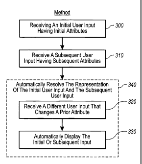
For example, Figure 3 shows that a method in accordance with the present
invention comprises an act 300 of receiving an initial user input having
initial
attributes. Act 300 includes receiving an initial user input to be displayed
through a
user interface, the initial user input having one or more initial attributes.
For example,
a user selects a table that has one or more static attributes related to
composition
and/or coloring, and then draws a corresponding table 140a in a design space
120.
The table 140a can contain one or more additional dynamic attributes that
relate to
length, width, numbers of legs, or corresponding mounting hardware depending
on its
position in the design space 120, or its position relative to another item
(e.g., wall
110a or 110b).
CA 02577199 2007-02-15
WO 2006/018740 PCT/IB2005/003248
13
Figure 3 also shows that the method comprises an act 310 of receiving a
subsequent user input having, subsequent attributes. Act 310 includes
receiving a
subsequent user input having one or more subsequent attributes that conflict
with the
one or more initial attributes, such that one or more af the initial user
input and the
subsequent user input are automatically, displayed in, a modified-form or
automaticallx
hidden from view. For example, the design software receives a subsequent user
input
for a table 140b, which the user initially places on top of the previouslX
placed table
140a (e.g., Figure 1C).
As previously described in Figure 1 C, the input of act 310 can result in some
lo cases in an initial conflict of user input, however, since the design space
120 does not
allow for non-real-world situations, and therefore does, not allow a table
(e.g., table
140b; Figure 1C) to be placed partially on top of another table (e.g., table
140a, Figure
1 C). Thus, the design software modifies one or more attributes related to
positioning,
numbers of legs, and mounting hardware, to create an appropriate modified
position
(or other attribute) for table 140b, as shown in Figure 1 D. That is, where
there might
be shared hardware, one or more otherwise viewable portions of the item might
be
hidden from view, since there is no need to show two of the same item in a
shared
space. In another exemplary case, such as where the user inputs an object such
as
plant (not shown) to be placed under table 140a, the object that is placed
under table
140a may. be completely hidden from view until the table 140a is moved or
modified
in some other way.
In addition, the method of Figure 3 comprises a step 340 for automatically
resolving the representation of the initial user input and the subsequent user
input.
Step 340 includes automatically resolving the representation of the initial
user input
and the subsequent user input based on at least one of the one or more initial
attributes, the one or more subsequent attributes, and any additional user
input, such
that at least the initial user input and the subsequent user input are
represented through
a user interface accurately in real-time. For example, upon recognizing a
conflict in
positioning between tables 140a and 140b in Figure 1C, the design software
3o automatically adjusts each of the different attributes of the two tables
each time the
tables so that they are viewed appropriately in the design interface, and so
that there is
an accurate parts list maintained.
CA 02577199 2007-02-15
WO 2006/018740 PCT/IB2005/003248
14
Accordingly, Figure 3 shows that step..340 comprises an act 320 of receiving.a
different user input that changes. a prior attribute. Act 320 includes
receiving a
different user input that changes at least one of the one or more initial or
subsequent
attributes. For example, a user moves table 140b away from table 140a (i.e.,
Figure
1 E), such that at least the position attributes of each table no longer
conflict in any
meaningful way. As such, step 340 also comprises an act 330 of automatically
displaying the initial or subsequent input. Act 330 includes automatically
displaying,
the initial or subsequent user input as originallX received. For example, the
design
software automatically, reverts at least a portion of the attributes in tables
140a and
l0 140b so that each has the appropriate number of legs and mounting hardware
(or lack
thereof). Thus, as shown in Figure 1E, both tables 140a and 140b have the same
basic
appearance in terms of composition and structure as the table icon 110
selected by the
user through the selection portion 102 of the design software interface.
Accordingly, the diagrams and methods provided herein illustrate a number of
ways and configurations in which design software can be used to automatically
adjust
prior, present, and/or future user inputs to create an accurate depiction of a
design
space. In particular, the design software in accordance with the present
invention is
configured to continually resolve conflicts in user input, as well as to
continually
resolve appropriate positioning of input in real-time. Furthermore, the design
software in accordance with the present invention accomplishes these ends
while
maintaining an accurate parts, list for each of the items placed in a given
design space.
Thus, implementations of the present invention represent an effective and
efficient
means for designing any interior and/or exterior space, and ultimately for
constructing.
the same.
Figure 4 and the following discussion are intended to provide a brief, general
description of a suitable computing environment in which the invention may be
implemented. Although not required, the invention will be described in the
general
context of computer-executable instructions, such as program modules, being
executed by computers in network environments. Generally, program modules
include routines, programs, objects, components, data structures, etc. that
perform
particular tasks or implement particular abstract data types. Computer-
executable
instructions, associated data structures, and program modules represent
examples of
the program code means for executing steps of the methods disclosed herein.
The
CA 02577199 2007-02-15
WO 2006/018740 PCT/IB2005/003248
particular sequence of such executable instructions or associated data
structures
represents examples of corresponding acts for implementing the functions
described
in such steps.
Those skilled in the art will appreciate that the invention may, be practiced
in
5 network computing environments with many types of computer system
configurations, including personal computers, hand-held devices, multi-
processor
systems, microprocessor-based or programmable consumer electronics, network
PCs,
minicomputers, mainframe computers, and the like. The invention may also be
practiced in distributed computing environments where local. and remote,
processing
10 devices perform tasks and are linked (either by. hardwired links,. wireless
links, or by a
combination of hardwired or wireless links) through a communications network.
In a
distributed computing environment, program modules may be located in. both
local
and remote memory storage devices.
With reference to Figure 4, an exemplary system for implementing the
15 invention includes a general-purpose computing device in the form of a
conventional
computer 420, including a processing unit 421, a system memory 422, and a
system
bus 423 that couples various system components including the system memory 422
to
the processing unit 421. The system bus 423 may be any of several types of bus
structures including a memory bus or memory controller, a peripheral bus, and
a local
bus using any of a variety of bus architectures. The system memory includes
read
only memory (ROM) 424 and random access memory, (RAM) 425. A basic
input/output system (BIOS)~ 426, containing the basic routines that help
transfer
information between elements within the computer 420, such as during start-up,
may
be stored in ROM 424.
The computer 420 may also include a magnetic hard disk drive 427 for
reading from and writing to a magnetic hard disk 439, a magnetic disc drive
428 for
reading from or writing to a removable magnetic disk 429, and an optical disc
drive
430 for reading from or writing to removable optical disc 431 such as a CD ROM
or
other optical media. The magnetic hard disk drive 427, magnetic disk drive
428, and
optical disc drive 430 are connected to the system bus 423 by a hard disk
drive
interface 432, a magnetic disk drive-interface 433, and an optical drive
interface 434,
respectively. The drives and their associated computer-readable media provide
nonvolatile storage of computer-executable instructions, data structures,
program
CA 02577199 2007-02-15
WO 2006/018740 PCT/IB2005/003248
16
modules and other data for the computer 420. Although the exemplary,.
environment
described herein employs a magnetic hard disk 439, a removable magrietic disk
429
and a removable optical disc 431, other types of computer readable media for
storing.
data can be used, including magnetic cassettes, flash memory: cards, digital
versatile
disks, Bernoulli cartridges, RAMs, ROMs, and the like.
Program code means comprising one or more program modules may be stored
on the hard disk 439, magnetic disk 429, optical disc 431, ROM 424 or RAM 425,
including an operating system 435, one or more application programs 436, other
.program modules 437; and program data 438. A user may enter commands and
to information into the computer 420. through keyboard 440, pointing device
442, or
other input devices (not shown), such as a microphone, joy stick, game pad,
satellite
dish, scanner, or the like. These and other input devices are often connected
to the
processing unit 421 through a serial port interface 446 coupled to system bus.
423.
Alternatively, the input devices may be connected by other interfaces, such as
a
parallel port, a game port or a universal serial bus (USB). A monitor 447 or
another
display device is also connected to system bus 423 via an interface, such as
video
adapter 448. In addition to the monitor, personal computers typically include
other
peripheral output devices (not shown), such as speakers and printers.
The computer 420 may operate in a networked environment using logical
connections to one or more remote computers, such as remote computers 449a and
449b. Remote computers 449a and 449b may each be another personal computer, a
server, a router, a network PC, a peer device or other common network node,
and
typically include many or all of the elements described above relative to the
computer
420, although only memory storage devices 450a and 450b and their associated
application programs 436a and 436b have been illustrated in Figure 4. The
logical
connections depicted in Figure 4 include a local area network (LAN) 451 and a
wide
area network (WAN) 452 that are presented here by way of example and not
limitation. Such networking environments are commonplace in office-wide or
enterprise-wide computer networks, intranets and the Internet.
When used in a LAN networking environment, the computer 420 is connected
to the local network 451 through a network interface or adapter 453. When used
in a
WAN networking environment, the computer 420 may include a modem 454, a
wireless link, or other means for establishing communications over the wide
area
CA 02577199 2007-02-15
WO 2006/018740 PCT/IB2005/003248
17'
network 452, such as the Internet. The modem, 454, which may be internal or
external, is connected to the system bus.423 via the serial port interface
446. In a
networked environment, program modules depictect relative to the computer 420,
or
portions thereof, may be stored in the remote memory storage device. It will
be
appreciated that the network connections shown are exemplary and other means
of
establishing communications over wide area network 452 may, be used.
The present invention may be embodied in other specific forms without
departing from its spirit or essential characteristics. The described
embodiments are
to be considered in all respects only as illustrative and not restrictive. The
scope of
the invention is, therefore, indicated by the appended claims rather than by
the
foregoing description. All changes that come within the meaning, and range of
equivalency of the claims are to be embraced within their scope.