Note: Descriptions are shown in the official language in which they were submitted.
CA 02577403 2007-02-06
~~.~ ~ .~.
=lA3rplarie 9cclX +srsd Method ;9b;c D3Assvafncttiar9.szg st"
xhe iriveritiori refers Lo an cra.xplane body, in partiCts,lar the
fuselage, eamprisxng at least two parts, manufactured
pzeferably from synthetic material, wherein the parts are
joined to each other at their edges. The invention also refers
to a m thod for manufacturix1g such an airplane body.
Airplanes manufactured from synthetic material are already
known. Here single parts of the airplane are manufactured in
parts, and they are, after that, joined by glueing.
Recently airplanes of this type made from synthefi5.c material
are also used foz long distance flighLa which are carried out
for economical reasQns. very high above which requires that for
pilot and passengers a pressure cabin is provided. This
pressure cabin must resist a prnssure difference between the
inside prossuxe and the considerably Iower outside pressure in
a relatively large height.
The invention is based on the problem to stabilise the
a,i.rQl.ane, in particular the fuselage of the airplane, in
particular in, the region of the pressure cabin.
AccArding to the iAventlon this problem is solved by providing
the fuselage or the parts at least partly with a
reinforcement.
According to the invention the problem is solved by the fact
that aTi airplane bvdy, in particular a fuaelage, is suggested
which consists of at least two parts preferab7.y m.anufactuzed
from synthetic material, wherein the parts are joined to each
other at their edges, and the airplane body or the parts are
provided at least partly with a reinfoxcement. The
r=dinforcerQent suggestod according to the invention has the
effect to increase the stability of the a,irplane body. It has
to be taken into oonsidexation that the airplane for the air
traffic in large heights is exposed to a pressure difference
betweon outside skin and inside of about 0.5 8ar. Thxs h,a,ghex
inside pressure bldws up the airplane body, th,ra roinforCetrient
CA 02577403 2007-02-06
2
roaches a suffici.ent atabili,4atia0. By means of the suggestion
accaxding to. the invention it will be possible to use eirpJ.ane ,
bodies according to the invention also fox planed which fly in
'hei ght9 above 3, 400 meters.The field of use of airplane
bodios from synthoti,c material, already known for g].iders or
light motor planes, is widened considerably by the suggesti.on
according to the invention, and weight is saved. Vor that
airplanes designed according to the invention have a larger
ranc~e by thQ higher atnoUnt of fuel on board.
Accoxding to the invention it is provided here that the
reinforcement runs angularly, in particular rectanguXarly, to
the edge, and in particular reaches over the edges of the
adjoining parts. The invention is here not restricted Gnly to
the suitabJ.e stiffening of the part forming the airplane, but
stabilises and stiffens, rospcctively, also the link region
at the verges of two adjoining paxts acQoarding],y. It is
cleverly tried to achieve here tnat the rexnfoxcement is, for
example, gua.ded annulax].y around the airplane body and thus
leads to a stiffening.
As a possibility it ia prUv%ded ko sheathe the a;i.zplane body
at least in the region of the pressu,re cabin. Also
reinforcement fi.bexs insexted in the material of the parts are
posslble. However, the reinforcements reaching across the
verges can only be arranged with dif,f5,cultie;s,
zt has proofed to be in particular convenient to provide the
parts of the airplane body on its outside with a casing so
that by means ot this casing the parts of the airplane body
are kept together. Ia particular, accordi.ng to af5.rsti
embodiment, at least the pressure cabin i.s enclosed in certain
di.standes radially by bi.nders which do riot only hold together
the two paxts of the airplane body at their verges but also
reinforce the other region of the airplane bvdy. Despite the
high pressure in the pressure cabin the shapa of the pressure
cabin remaine the same essentially. For example, the binders
cqnsist vf fiber reinforced synthetic laminate where, in
particular, carbon fibers are used as fibezs.nso glass
fibers or synthetic fibers are very well suited for
reinforcing the laminate as they are very light weight, the
same as carbon fibcrs, and can be stron+gly tension-loaded. By
introducing aluminium fibers into the binders around the
pressure cabin a so~cal.led Faraday cage forms which protects
the a3.rplane aqainat lightning.
The binder consist of stripes about five to twenty centimeters
wi,de wi=tlf a thickness of about one to five mil].imetexs. At
least in the region of the joined verges of the paacta binder
sections are arxanged which the additionally hold together the
glued seam. ACcording to another ernbodiment the binders are
put radially around the airplane body, and are coni3eCted to
CA 02577403 2007-02-06
3
each othex at their ends. Thus an annulax design of the
binders is cxeated. For connecting these ends to one anotiher,
in particular, epoxy resin is suited as g}.ue which has already
been used for lama,nating the two parts of the airplane body.
According to the invention it is convenient to use as glue for
forming the binder the same glue as it haa boon used also in
the manufacturing the part ol the aixp],ane body consisting of
synthetic matiar,ia].. The binders are not only at their ends
oonnected to each other but, by means of thg epoxy resin, are
also glued to the airplane body. The p],acf.nq of the binders is
thus stabilised. xhus slipping is impoasa.ble.
Besides these binders which suxxoun.d the airp],3ne body
radially - called in the following radial binders - also
binders are provided at the airplane body which are arranged
transversely to the longitudinal axis of the airplane body.
These txa,ns=verse binders are cl.amped, for example, axound the
pressure ribs which close the pressure cab.in at the front axxd
back end. The ribs themselves aze glued to the airplane body,
and, for xe,infozcxag the glue verges, reach across the
txanmvorse bxndexs of the pressure ribs diagonally, are bent
at the verges of the pressure ribs, and run across a certain
range along the outside wall of the presguxe cabin. The
out,side wall is, according to another embodiment, formed by
the parts the airplane body consists of. Therefore it is
cQnvenient to guide the traftsverse binders covexing the
pressure ribs from the inside of the airplane body to the
outside; for that lpurpose in the wa1,1 of the airp],ane body
recesses are provided. These recesses are designed slot--like
the dimensions of which are such that the binders can be
easily guided thxough. At least on th# outside of the airplane
bady tne binders are giuad with the fuselage. xowever, also in
the region of the pressure ribs a glue connection reinforces
the link between binder and pressure rib.
According to another embodiment the transverse birtdexs can be
guided across the entire 7,ength of the pressure cabin, and
encl.oae the opposite pressure rib, wherein the transverse
binder as also the radial binder are glued tvgether at Lheir
ends, and thus encloses the pressure cabin completely in
longitudi.na], di.xectxon to the longitudinal axis of the
airplane. Therefore the pressure Gsbin is surrounded by
skeleton-like azranged binders which enclose at least the
pressure cabin corset-like. With little effort of material a
fra.me-like 9uppoxt for the pressure cabin is formed.
Just the radia], binders run rectangularly ta the verge of the
two half shell,s of the airplane body. Through the rectangular
arrangement of the binders to the verges the parts of the
aa.rplahe body are held togetiier with minimal, expetiditure vf
force.
CA 02577403 2007-02-06
4
The radial binders are, according to an embodiment of the
invention, designed in one piece, that mean's they consist of a
tape which is joined at its ends.The transverse binders rear.h
in aa embodiment over the pressure cabin only partly in
].ongitudina7, di.rectxon. However, there is the possibi,llty to
arrange longitudinal bi,nders (paralxel to the l,ongitucli,.nal
axis of the $irp],ane) at the ends of the transverse binders
which, fox example, connect the transverse binders at the back
pressure rib with the transverse binders of the fzent pressure
rib. Thus the transverse binders consi.st of sections which are
connected to ea,Gh othex.
It has turned out to be especia7,].y convenient that airplane
body and binder consist of the same matarial. In this way a
gluein5 of the bi,hders with the aixplane body by means 8f
epoxy resin is absolutely posoible. Besides the rddial binders
and traverso binders which embrace the preasure cabin
furthermore longitudinal binders are provided at the airplane
body which extend, for exampl,e, from the nose of the ai.rpl$n$
body to the region of the tailplane. In this way not only the
region of the pz asure 4abin is reinforced but also the
complete airplane body. It has proofed to be particularly
efficient also to connect the different binders, radial,
longi.tvdinal and/or transverse binders, at points where they
cross each othex, At theae points several layers of binders
are placed one upon the other. According to arnothex embodiment
of tne invent9.on it is provided to arrange not only one layer
of a binder at the airplane body but, perhaps, two or three
layers one upon the other so that an even better xeinforcement
of the airplane body becomes ,possible. The bindar may also be
guided along the verge of the two parts cf the airplane,
wherein these binders are embraced additionally = by radial
binders. rn another embodiment of the invention it i,s provided
that, for exantple, longitudinal binders are paxtly divided
longa,tud3.nal].y, that means a part of the longitudinal binder
extends from the front tip of tho airplane body to its and,
and the other part of the ,ioKxgltudinal birider encigc],es the
airp7.ane body in the region of the pxessure cabin. Along the
longitudinal axis of the pressure cabin thus the two parts of
the 1 nngitudi na l bxnder are supported by the outside of the
airplane body, wherein at the end of the pressure cabin a part
of the longitudinal bin.der is intzoduced into the interior of
the airplane, and, if necessaxy, 5.s guided out again on the
opposite side.
Adcordi,ztg to the invention the skeletal structure of the
reinforcement is arranged on the outside of the preoQure cabin
or partly on the outside of the airplane body, and is
supported on the surface of the airplane body. By zneans of the
thickness of the bxndexs in the range of about one to five
millimeters between thp pdges of the binders and the surface
CA 02577403 2007-02-06 --
$
of the airplane body a sheulder fs formed w}1ich is smoothed in
order to keep the flow resistance low.
According to another ac]vantageou,s modification of the
invention on the exterior surface of the airplane body
iodenta t:f.ons are provided the wa.dth and depth of which
correspond roughly with the dimensions of the b.inder. Thus the
b~nders do not project beyond the surface of the airplane
body. The gap forming between the edges of the binders and the
edge of the indentation is also smoothed. Also the recesses
which are provided for threading, for Qxarnple, the transverse
binders from the inside of the airplane body to the outside
are Closed with knifing filler.
Tha arrangemezst of the binders at the a1.r.Qlane body 9,s such
that openings like doors, windows and the like are arranged in
the regiou between the different binders. As the uppez verge
of the door is arranged as a xule f higher than the upper verge
of the windows It is, however, also possible to arrange the
longituda.nal binders in diffezent planes, that means in the
region og the openizxg of the door the longitudinal bindez is
guided above the upper verge of the door, and in the region of
the windvws, for example, a bit lower. In arder to reinforce,
for example, the fastening point tor the wings, also two
radial binders Enc7.osing one window dxe lead together in the
region of the wings. In the upper region of the airplane body
the two radial binders are arxanged, splced f and in the lower
region these two radial binders are close to each other. The
optimal embodiment of this skeletal reinforcement is two
binders which cross each other at a right anqle. Because of
the shape of the alrplane body, however, other arrangements of
the btnders are necessary which take tho ahape of the airplane
body into consideraLio[x.
Besides the design of the airplane body, with the xnvent3on
also the method for manufacturing the airplane body is
claimed. The manufacturing of an aixplane body of this type
fzom at lersst two, in particular synthetic, parts comprises,
first of al7., the step to produce the sing7.e parts of the
airplane body. This is done, fox example, in the ].aminatring
process, in particular, in a hand laminating process where
fleeces saturated with epoxy resin are glued vne upon the
other in a mould. After hardetiag of these parts of the
airplane body they are assembled and glued together at their
verges (these are, for example, flanges). At least at the
con,riectxon regions of both paxts together the verges are
covered by reinf'oroements, The reinforcemQnts consist
conveniently of binders which arc also glued to the airplane
body. ei.nder and ai,zp7.ane body consis=t advantageously of the
same material so that for glueing of binder axLd airplane body
alsa epoxy resin may be used, It has turned aist to be
convenient to wrap the combined parts of the airplane body
CA 02577403 2007-02-06
6
with binders, for thaL puYpose radial, transverse and/or
longitudinal binders are used.- These binders form a skeleton
which reinforces the outside of the airplane body, in,
particular the pressure cabin, These binders may be qn top of
the surface of th.e airplane body, or they are inserted in
indentations in the surface of the airplane. Tho shoulders
which~ acaur between the edges of the binders and the xux.Zace
of the airplane body or the edge of the inderttation are
smoothed after that so that nv dents remain on the surface of
the azrp7.ane body. The xecesses fox guiding out the transverse
binders from the intexiox of thA airplane body to the outside
are also smoothed.
In thx9 connection it is in particular poa.nted out that all
features and charactexistics but a].9n methods described with
reference to the airplane body accordingly may be transferred
also with reference to the formulation of the method according
to the xnvention, and can be usad in the sense of the
invention, and are seen also as disclosed. The same goes vice
versa, that means all constructive, that means device,
charactc.ristxcs mentioned ' only with reference to the method
may also bm Laken into con9ideration, in the frame of the
cle.ims of the airplane, and be claimed, and also courit a.s part
of the invention and disclosure.
In the following the invention is described in deta i?. by means
of a drawing. In the drawing:
Fig. 1 a cutout of an airplane body
according to the inventian in a side
view;
E'ig. 2 a three-dr.mensional vipw of the
blnders as they surround the
fuselage, according to the
invention;
rig. 3 a view ot a rib of an airplane body,
according to the xnvention, and
Fig.4 a three-dimensional view of an
aixp].ans body, according to the
invention, with the side part
removed.
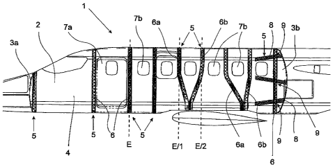
The fuselage 2 of an airplane 1. shown in the figuses comprises
two pre-fabricated, synthetic half shells 21 thg connection
plane of which is orientated vertically along the longitudinal
axis of the airplane 1. Thus the fuselage 2 consists of a
right and a left half shell 21 as the parts from which the
fuselar~w_ 2 is manufactured. According to this znbodi.ment the
half shcl,ls 21 are structured in multiple layers, and are
CA 02577403 2007-02-06
7
"leminated in a mould. After finishing the two half she3.].s 21,
they are connected to each other by glut;iag.
For reinforcing the fuselage 2 ribs 3 are provided at the
fuse].age 2. In particular, the pressure cabin 4 is closed at
its front and baak end by pressure ribs (3a, 3b). Ti1A pressuze
cabin 4 is a self-contained space. it is not necessary to
provide the entire intexivr of the fuselage 2 with pressure.
According to the invention, in particula,t with a synthetic
fuselage 2. in the region of the pressure cabin 4 a
reinforcement 5 is provided so that the fuselage 2 of the
airplane 1 in the region of the prcwsure cabin 4 is not
destroyed because of the pressure difference between interior
and exterior pressure. This reinforcement 5 consists of
binders 6, 8 which encircle, in the embodiment accoxding to
Fig. 1, the fuselage 2 in transverse directxon to the
longitudxnal axis of the airplane or to the airplan.e body.
These birYders 6 are called in the following radial binders 6.
At the end of the pressure cabin 4 the pressuze rib 3b is
reinforced by transverse binders 8 which are guided from the
interior of the fuselage 2 through recesses 9 to the outside
of the fuselage 2. Tha binders 6, 8 are glued to the fuselage
2.
Advantageously these binders 6, 8 consist of carbon fiber
reinforced s,yntheta,c lazoinate, This synthetic laminate can be
loaded very strongly with tension, and the binders 6, 8
enclosing thu~s the fuselage 2 keep the pressuxe cabin 9
togetlier. xhe wall of the tuaelage 2 is -reinforced by these
binders 6. Carbon fibe,r reinforced synthetic material.s are
essentially lighter compared with m talõ In paxtxculax
lowering the weight is decisive in airplane engineering.
Conveniently the material of the binders 6, 9ig the same as
the material of -the fuselage 2.
In Fig. 1it can be seen that the binders 6, 8 are azranged
only Jn the region of the fuselage 2 which do not carry
openings 7, fo,r example for doors 7a and windows 7b. In the
optimal enibodimQnt the binders 6 wrap the fuselage 2 in a
plane &. This is the shortest distaxace to enclose 'the fuselage
and the mechanically most stabla one.
As it can be seen, the binders 6a and 6b are also arranged in
such a way that they encircle the fuselage 2 in differeot
planes E/1, E/Z, xn the upper region the binders Ga, 6b are
spaced, and in the bottom region the two binders 6a, &b s,xe
close together, for example in order to reintorce the
fastening point for the wing. Between the binders 6a, 6b the
opening '7b for a window is provided which is enclosed partly
by the binders $a, 6b.
CA 02577403 2007-02-06
~
At the end of the preasuxe cabin 4 at the back rib 3b the
binders 8 are orientated in such a way that they embrace the
rib 3b essentially horizontally or vertically. The ends of the
binders 8 are bent and reach over the fv,gelage 2 at least
partly in longitudin.al direction.
As the binders 6, 8 are arranged on the outside of the
tuselag2 2 these binde-ts 8 are guided in the region of ttie
zi.bs 3b to the outside from the interior of the fuselage 2
through pre-fabr,ica,ted recesses 9. After finishing the
airplane these recesses 9 are covered. Alternatively, these
binders 8 may aiso be connected with longitudinal binders
arranged at the inside at the fuselage 2.
The width of the binders 6, 8 is dimensioned in such a way
that the bindars 6, 8 rott 'be arranged in the interval between
the openings 7, for oxample the windows 7b and the doors 7a_
The maximum width thus corresponds with the minimum distance
between two openings 7.
However, it has turned out to be convenient to produce binders
6, 8 with a width of about 5 cm toa 20 cm, preferably 10 cm.
These binders 6, 8 reinforce the pressurc cabin 4
sUfficiently.
In an embodiment the bindexs 6, 8 are glued to the surface of
the airpl,ane fus.alage 2, whexexn as glue convenietatl,y a
synthetic resin, for example epoxy resin, is ussd.
According to another advantageous em.bodiment in the tuaelage 2
indenta,tiorxs are provided for holding the binders 6, 8. Tn
this way the binders 6, 8 are guided on the Zuselage, and do
not project beyond the surfacs of the fuselage 2. The shoulder
or gap remaining rietween the edge of the binders 6, 8 is,
after that, smoothed so that the surface o:C the airplane 1, i,s
smooth.
The thickness of the binders 6, 8 is in a range between 1 to 5
mm. However, it has turn d out to be convenient to design the
binders 6, 8 with a thickness of 2=, Thi3 leads to a
sufficient stability of the pressure cabin 4. The clepth of the
indentation is advantageously adapted to the thickness of the
bi.-nders 6, S.
The binders 6, 8 are conveniently bui.lt from the same material
as the parts of the airplane body 2. These consist, for
example, of a ayntbetic fiber composite structure whaze, tor
examp]e, a multilayer fleece from caxbon,, glass or aramide
fibers is saturated with epoxy resin. Aluminium threads
integ=rated in the binders 6, 8 offer a lightning pxoteetion,
CA 02577403 2007-02-06
9
4
In Eig. another arrangement of binders is shown. Aecording
to this example besicles l.be xedial and transverse binders 6, 8
also longitud5.;nal binaers 10a and 101a, 12 to 14 are provided
whiCh are arranged para.llel to the longitudizaal axis. The
longitudinal binders 10a extend, for exainple, from the back
region of the pressurg cabin (not shown) m99entially parallel
to the, longitudinal axis to the front pxessure rib (not shown)
of the pressure cabin.
The binders 12 and 13 project qver the front pressure rib 3a,
and r_e,inforc:e at the same time the nose of the airplane.
The back ends of the longitudinal, bindexs may bo clampad over
the back rib 3b, or they xun further on the surface of the
fuselage 2 to the back xega.on of the aixpJ.ane 1. The
longitudinal binder 14 is in the back region of the fuselage
attached a bit lower than in the front region. This
arrangement is, for exampl,e, caused by the arrang ment of the
door 7a which is provided in the region between the two
binders 6a, 6b. In the region between the twp transverse
binders 6a, 6b the longitud3,nai binder 14 runs above the
opening (not skaown) of the door 7a, while the window 7b is
arranged, for example, a bit lower so that the longitudinal
binder 14 in the regioa of the transverse binders 6c, 6d may
be arranged a bit lowex. The longitutiinal bincters embrace
here, according to the invention, the airplane body 2
consisting of two parts as well as only one pe,zt of the
airplane body F In this mociification an improvement of
stability ia reached.
As desori.bed the longitudinal binders are designed suitably
extended to the front and back so that, for example, in the
regi. on of the pressure cabin a sepaxation of the longitudinal
binder is the result in such a way that a part of the binder
is extended to the back ox to tho front, arid the other part
wraps the pressure cabin 4. such an embodiment is pdssible
without any problezts by the design of the binder in the
deecribed laminate stxucture.
Fig _ 3 ahowp one of the pressure ribs, for examp],a the back
rib 3b, in a top view, the 7.ongitudinal binders reaching over
the rib diagonally. The longitud~nal biudezs 17, 18 and 10 are
a.rratged to one another in such a way that they form an angle
wi.rh each other in the region of the rib 3b. The opening,s,
elevations or indentations 20 shown in Fig. 3 are not covered
by the binders 17, 18 and 19.
After finishing the airplane body 2 the synthetic body is
hardened at about 80 C. ay means of the invention thus a
stable cdn,strvcti on is rnanufactured ;.n order to be also able
to rnanufacturc airplanes I with lpressure eabins 4 made from
CA 02577403 2007-02-06
synthetic mater3aa, in the hand laminating method (not in the
a;utoc].ave1.
In Fig. 4 the airplane according to the invention is shown in
a pa,xt visw. This airplane body 2 consists of a half shell 21
of laminated synthetic layers. In this half shel.l 21, tor
example, trie windows 7b already are alrea,dy left open, and the
tranaVerse binders 6 extend around the airplane body 2 between
the windows y_ The fJ,ovz plane 22 of the f'inished fuselage is
already provided in the halt shell 21. Furthermoxa in the
aixplanp body 2 ribs 3 can be seen which stabilise the
airplane body 2. These ribs 3 are provi,ded over the entire
zegidn of the airplane body 2, and extend to the tailplane of
the airplane 1. In particular the region where the Q~lot and
the passengers are is closed at both ends with the pressure
ribs 3a, 3b, and forms together with a part ot the airplane
body 2 the pxrssure cabin 4. Longitudinal xS.bs are not shown
in this figure, they can only be 9een xn the region of the
ribs 3a and 3b, however, they extend, as shown in Fig, 2,
parallel to the longitudinal, axis of the airplane.
The invention is dascrzbed in particular in connection with
the design of an airplane body in synthetie constxuction
(fzper reinforced syslthetic composite with epoxy resin}.
However, the invention is not restricted to that. The result
according to the invention may also be reached in the same way
with airplane bodies whir_h consist of another material (for
examplo tnotal, light metal and so on), or composite materials
(for exampl.e different materials of the part and the
xei.nfoxcement ) .