Note: Descriptions are shown in the official language in which they were submitted.
CA 02577577 2007-02-08
25.0373
WELL DEPTH MEASUREMENT USING TIME DOMAIN REFLECTOMETRY
TECHNICAL FIELD
[0001] The invention relates generally to determining a well depth by
measuring a
length of an electrical cable using time domain reflectometry.
BACKGROUND
[0002] It is often desirable to determine the depth of a downhole component,
such
as a tool carried on a carrier line that has been deployed into a well.
Typically, the carrier
line is wound on a spool or reel at an earth surface location. To deploy a
tool on the
carrier line into the well, the carrier line is unwound from the spool.
[0003] Conventionally, a depth wheel sensor is provided at the earth surface
location proximate the spool to determine an amount of carrier line that has
been
unwound from the spool. The depth wheel sensor includes a wheel or roller that
is
rotated as the carrier line is unwound from the spool. The number of rotations
of the
wheel is used to determine the length of the carrier line that has been
unwound from the
spool and lowered into a well.
[0004] This technique for measuring the length of carrier line that has been
deployed into a well is not very accurate. As a carrier line is deployed into
the well, the
carrier line length will change due to environmental conditions (e.g., changes
in
temperature and/or pressure) and due to strain applied by the weight of the
carrier line as
well as the tool carried on the carrier line. The depth wheel sensor for
measuring the
length of carrier line that has been deployed into the well does not account
for such
length changes.
1
CA 02577577 2007-02-08
25.0373
SUMMARY
[0005] In general, according to an embodiment, the method includes deploying a
component into a well on a carrier line that includes an electrical cable, and
determining a
depth of the component in the well using a time domain reflectometry
technique.
[0006] In general, according to another embodiment, a system includes an
electrical
cable for deployment into a well, and a measurement device electrically
coupled to the
electrical cable. The measurement device transmits an electrical pulse into
the electrical
cable, detects a reflected signal due to an impedance mismatch in the cable in
response to
the electrical pulse, and determines a length of the electrical cable based on
the
transmitted electrical pulse and the detected reflected signal.
[0007] Other or alternative features will become apparent from the following
description, from the drawings, and from the claims.
BRIEF DESCRIPTION OF THE DRAWINGS
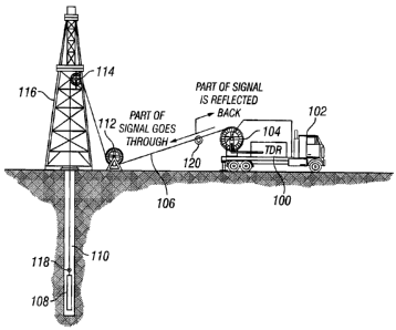
[0008] Fig. 1 illustrates a first exemplary arrangement that includes a
measurement
device according to some embodiments for determining a length of a carrier
line
deployed into a well.
[0009] Fig. 2 illustrates positions on the carrier line subjected to
temperature
change to create an impedance mismatch at an earth surface location, in
accordance with
an embodiment.
[0010] Fig. 3 is a block diagram of a measurement device setup according to an
embodiment.
[0011) Fig. 4 illustrates a second exemplary arrangement that includes a
measurement device according to some embodiments for determining a length of a
carrier
line that has been deployed into a well.
2
CA 02577577 2007-02-08
25.0373
[0012] Fig. 5 illustrates a third exemplary arrangement that includes a
measurement
device according to some embodiments for determining a length of carrier line
that has
been deployed into a well.
[0013] Fig. 6 is a block diagram of a measurement device setup according to
another embodiment.
[0014] Fig. 7 is a flow diagram of a process performed by the measurement
device
according to an embodiment.
DETAILED DESCRIPTION
[0015] In the following description, numerous details are set forth to provide
an
understanding of the present invention. However, it will be understood by
those skilled
in the art that the present invention may be practiced without these details
and that
numerous variations or modifications from the described embodiments are
possible.
[0016] In accordance with some embodiments of the invention, a measurement
device is used to transmit an electrical pulse into an electrical cable
associated with a
carrier line (e.g., an electrical cable in a wireline, an electrical cable in
a slickline, an
electrical cable deployed in tubing, and so forth) that is used to deploy a
tool or other
component into a well. The measurement device detects a reflected signal due
to a
downhole impedance discontinuity (or impedance change) in the carrier line,
where the
reflected signal is in response to the electrical pulse. The downhole
impedance
discontinuity can be at the most distal end of the electrical cable or at some
other
downhole location.
[0017] The overall travel time of the electrical pulse from a reference point
at an
earth surface location to the downhole impedance discontinuity, and of the
reflected
signal from the downhole impedance discontinuity back to the earth surface
reference
point, can be determined. This overall travel time is converted to distance
(the estimated
3
CA 02577577 2007-02-08
25.0373
length of the electrical cable that has been deployed). Based on the measured
length of
the electrical cable that has been deployed into the well, the depth of a tool
or other
component can be determined. The above technique of transmitting an electrical
pulse
into an electrical cable and detecting a reflected signal for computing the
length of the
electrical cable is a time domain reflectometry (TDR) technique.
[0018] Fig. 1 illustrates a first exemplary arrangement that includes a TDR
measurement device 100 according to some embodiments. The measurement device
100
is depicted as being deployed on a vehicle 102. In other implementations, the
measurement device 100 can be deployed on another platform (e.g., wellhead
equipment
either at a land well or a subsea well, a sea vessel, or other platform).
[0019] Fig. 1 also shows that the vehicle 102 includes a spool 104 that
carries a
carrier line 106. The remote (or distal) end of the carrier line 106 is
attached to a tool
108. To deploy the tool 108 into a well I 10, the carrier line 106 is unwound
from the
spool 104. The carrier line 106 is directed into the well 110 by sheaves 112
and 114
associated with wellhead equipment 116.
[0020] The carrier line 106 includes an electrical cable having a remote (or
distal)
end electrically coupled to the tool 108. The remote end of the electrical
cable is
associated with an impedance discontinuity (either a short circuit, an open
circuit, or
other impedance change). The remote end of the electrical cable thus forms a
reference
point 118. Another reference point 120 is defined at an earth surface location
(discussed
further below). In the ensuing discussion, the earth surface reference point
120 is
referred to as a "first" reference point, and the downhole reference point 118
is referred to
as a "second" reference point.
[0021] In an alternative implementation, instead of providing the second
reference
point 118 at the remote end of the electrical cable, it is noted that the
second reference
4
CA 02577577 2007-02-08
25.0373
point 118 can be provided elsewhere along the electrical cable. Note that the
second
reference point 118 is the point in the well (corresponding to a location or
depth of a tool
or other component, for example) at which an electrical pulse transmitted down
the
electrical cable is reflected back up the electrical cable.
[0022] As further depicted in Fig. 1, the first reference point 120 is located
proximate the output end of the spool 104 (the output end of the spool is the
point of the
spool at which the carrier line is unwound from the spool). The first and
second
reference points depicted in Fig. 1 allow the measurement device 100 to
determine the
length of the electrical cable between the first and second reference points.
This length is
used to derive the length of the carrier line 106 that has been unwound from
the spool
104, and the depth of the tool 108 that has been deployed into the well 110.
[0023] The first reference point 120 includes a localized impedance change in
the
electrical cable at the earth surface. One technique of providing this
localized impedance
change is by heating and/or cooling one or more points of the electrical cable
such that
the impedance at the one or more points of the electrical cable is different
from the
positions of the electrical cable adjacent the heated/cooled point(s). In this
manner, any
electrical pulse generated by the measurement device 100 and transmitted into
the
electrical cable causes reflection from both the first and second reference
points 120, 118.
Although temperature change is one technique of causing a localized impedance
change
at the earth surface location proximate the spool 104, other techniques for
causing the
localized impedance change can be used.
[0024] When the electrical pulse generated by the measurement device 100
encounters the impedance change associated with the first reference point 120,
a part of
the electrical pulse is reflected back to the measurement device 100 as a
first reflected
signal. The remaining part of the electrical pulse continues into the
electrical cable until
CA 02577577 2007-02-08
25.0373
it reaches the second reference point 118. As a result, a second reflected
signal is
generated that travels back to the measurement device 100.
[0025] The first reflected signal is used to determine the amount of
electrical cable
remaining on the spool 104, while the second reflected signal is used to
determine the
entire length of the cable, which includes the length of the electrical cable
on the spool
104 and the length of the electrical cable that extends from the spool 104
into the well
110. The length of the electrical cable remaining on the spool 104 is then
subtracted
from the entire length of the electrical cable to determine the length of the
electrical cable
between the first and second reference points 120 and 118.
[0026] An issue associated with transmitting an electrical pulse into an
electrical
cable is that the electrical pulse may suffer dispersion and attenuation.
Dispersion causes
the electrical pulse length and shape to change, since dispersion causes the
pulse length to
increase. Attenuation causes the amplitude of the electrical pulse to be
decreased. Note
that the electrical cable is typically a dispersive and lossy medium that
causes the
dispersion and attenuation. As a result of dispersion and attenuation, it
becomes difficult
to detect reflected waveforms such that accuracy is adversely affected.
Dispersion and
attenuation of waveforms in the electrical cable results in a decline of
spatial resolution in
the TDR system. The spatial resolution of a TDR system is defined by the pulse
length,
amplitude, and shape of the transmitted electrical pulse.
[0027] Certain types of waveforms are subjected to dispersion, including
quasi-sinusoidual waveforms. However, other types of waveforms do not suffer
from
dispersion even when propagating in dispersive media. One such waveform is an
exponential waveform. Although the exponential waveform does suffer
attenuation in a
lossy medium such as the electrical cable, the shape of the pulse' of the
exponential
waveform is preserved over the propagation path associated with the electrical
cable.
Since the exponential waveform does not broaden as a result of propagation
along the
6
CA 02577577 2007-02-08
25.0373
electrical cable, the spatial resolution is relatively small (e.g., such as on
the order of a
few parts per million), to allow for accurate length measurement in different
types of
electrical cables.
[0028] In accordance with some embodiments, the TDR measurement device 100
that implements the TDR technique uses an exponential signal as the input
electrical
pulse. Such a TDR measurement device is referred to as a high spatial
resolution TDR
measurement device.
[0029] As noted above, Fig. 1 provides for a localized impedance change at the
first
reference point 120 that is caused by temperature change of the electrical
cable. It is
noted that a sudden change in the electrical properties of the insulation
associated with
the electrical cable (where the electrical properties include permittivity or
permeability)
may result in a strong enough reflection that the measurement device 100 can
detect a
reflected signal from the first reference point 120 and determine its
position. Permittivity
is a function of temperature. Therefore, changing the temperature at a given
position
along the electrical cable results in an impedance change.
[0030] Fig. 2 shows an example of the first reference point 120, where one
position
122 of the electrical cable is subjected to heating (such as by a heater, not
shown), and a
second position 124 is subjected to cooling (e.g., by a cooling device, not
shown). The
first reference point 120 is thus associated with both a heated position and a
cooled
position to cause the impedance mismatch. In alternative implementations, the
reference
point 120 is only either heated or cooled (and not both).
[0031] Fig. 3 shows a first setup for the measurement device 100. As depicted
in
Fig. 3, the measurement device 100 includes a function generator (signal
generator) 202
for generating the waveform (electrical pulse) that is transmitted into an
electrical cable
200 (such as the electrical cable in the carrier line 106). The measurement
device 100
CA 02577577 2007-02-08
25.0373
also includes a detector 204 (e.g., an oscilloscope) for detecting reflected
signals in the
electrical cable 200. A triggering signal 206 is provided between the function
generator
202 and the detector 204 to allow the function generator 202 to trigger the
detector 204
when the function generator 202 generates and transmits an electrical pulse
into the
electrical cable 200. Control of the function generator 202 and detector 204
is performed
by a computer 208 (e.g., a portable computer). Also, the computer 208 performs
data
acquisition and processing according to some embodiments. The computer 208
includes
software 210 that is executable on one or more central processing units (CPUs)
212,
which CPU(s) 212 is (are) connected to a storage 214. The software 210
controls when
the function generator 202 produces an electrical pulse for transmission into
the electrical
cable 106, and the software 210 is able to receive data relating to reflected
signals (e.g.,
first and second reflected signals from the first and second reference points
120, 118)
detected by the detector 204.
[0032] In the arrangement of Fig. 1, the detector 204 detects two reflected
signals, a
first reflected signal from the first reference point 120, and a second
reflected signal from
the second reference point 118. Data relating to these two reflected signals
is received by
the software 210, which can then estimate the length of the cable that has
been deployed
into the well 110 (estimated based on the length of the electrical cable
between the first
and second reference points). The software 210 can store the received data and
the
calculated length in a storage 214. Also, the computer 208 can output the
various data
associated with the TDR technique to the user, such as on a display.
Alternatively, the
computer 208 can send the data to a remote location, such as over a network
(either a
wireless network or a wired network).
[0033] The function generator 202 is connected to a directional coupler 216.
The
function generator 202 transmits an electrical pulse over a cable segment 218,
which
cable segment 218 is connected to one input of the directional coupler 216.
The
directional coupler 216 directs the electrical pulse from the cable segment
218 into the
8
CA 02577577 2007-02-08
25.0373
electrical cable 200. Any reflected signal that is reflected back from the
electrical cable
200 passes through the directional coupler 216 to a second cable segment 220
that is
connected to the detector 204.
[0034] Fig. 4 shows an alternative arrangement that includes use of a wheel-
based
sensor 302 (e.g., an integrated depth wheel). Basically, the wheel-based
sensor includes a
roller or wheel that rotates as the carrier line is spooled or un-spooled. The
wheel-based
sensor 302 provides an output indication to indicate the amount of carrier
line that has
been unwound from the spool 104. The remaining components of the arrangement
of
Fig. 4 are identical to the components used in the arrangement of Fig. 1, and
thus share
the same reference numerals.
[0035] In the Fig. 4 arrangement, a localized impedance change at reference
point
120 (in Fig. 1) is not provided. Instead, the wheel-based sensor 302 provides
the first
reference point 120 to allow the measurement device 100 to determine the
amount of
electrical cable remaining on the spool 104. With the technique of Fig. 4, the
measurement device 100 sends an electrical pulse into the cable 200, which
electrical
pulse is reflected from second reference point 118 at the remote end of the
electrical
cable 200. The measurement device 100 measures the two-way travel time
associated
with the transmitted electrical pulse and the reflected signal to determine
the total length
of the electrical cable 200. The measurement device 100 then receives data
from the
wheel-based sensor 302 to determine the length of the electrical cable that
remains on the
spool 104. By subtracting the length of the cable remaining on the spool 104
from the
total length of the cable 200, the measurement device 100 can determine the
length of the
cable between the wheel-based sensor 302 and the reference point 118, such
that a depth
of the tool 108 can be derived.
[0036] Fig. 5 shows an alternative arrangement in which the spool 104 remains
on
the vehicle 102. However, the measurement device 100 has been re-positioned
such that
9
CA 02577577 2007-02-08
25.0373
it is electrically coupled to a position on the electrical cable 106 that is
proximate the
output end of the spool 104. The position at which the measurement device is
electrically
coupled to the electrical cable is the first reference point 120. The
electrical coupling
between the measurement device 100 and the electrical cable 200 employs an
inductive
coupler mechanism 402. An inductive coupler mechanism uses electromagnetic
coupling
to couple electrical signaling on one electrical conductor onto a second
electrical
conductor. In one implementation, inductive coupling employs magnetic
properties of
steel used in the armor of an electrical cable.
[0037] Fig. 6 shows the inductive coupler mechanism in greater detail. An
electrical pulse generated by the function generator 202 is provided onto the
cable
segment 218, which is directed by the directional coupler 216 onto a cable
segment 502.
Note that the cable segment 502 is separate (physically distinct) from the
electrical cable
200. The inductive coupler mechanism 402 includes a loop 404 that is provided
around
the electrical cable 200. The electrical pulse generated by the function
generator 202
induces an electrical signal in the electrical cable 200 due to inductive
coupling at point
400 on the electrical cable 200. The induced electrical signaling is then
transmitted down
the cable 200.
[0038] In the reverse direction, a reflected signal (such as the reflected
signal from
the remote end of the cable) travels back on the electrical cable 200 to point
400, where
the reflected signal is inductively coupled onto the cable segment 502 and
communicated
to the detector 204 through the directional coupler 216 and cable segment 220.
[0039] Fig. 7 is a flow diagram of a process performed by the measurement
device
100, such as by the software 210 executable in the computer 208 of the
measurement
device 100. The measurement device 100 generates (at 602) an input electrical
pulse
(e.g., an exponential waveform or some other type of waveform) for
transmission into the
electrical cable 200 that is to be deployed into a well. The measurement
device 100
CA 02577577 2007-02-08
25.0373
detects (at 604) a reflected signal due to impedance discontinuity in the
electrical cable at
a downhole location, such as a distal end of the electrical cable 200 that is
connected to a
tool (e.g., tool 108 in Fig. 1).
[0040] If the first or second arrangement (Fig. 1 or Fig. 4 arrangement) is
employed, the measurement device 100 also determines (at 606) the amount of
cable
remaining in the spool. As discussed above, there are several techniques of
performing
this determination, including providing a localized impedance change at a
location (first
reference point 120) proximate the output end of the spool, or by using a
wheel-based
sensor 302. If the third arrangement (Fig. 5 arrangement) is used, then the
length of the
cable remaining on the spool 104 does not need to be determined, since the
reflected
signal is received at a point (inductively coupled point 400 in Fig. 5) that
is proximate the
output end of the spool.
[0041] The measurement device next determines (at 608) the two-way travel time
for the transmitted input electrical pulse in the reflected signal, where the
two-way travel
time refers to the sum of a first travel time between the function generator
202 and the
second reference point 118, and a second travel time between the second
reference point
118 and the detector 204 in the measurement device 100. Based on the two-way
travel
time, the measurement device 100 calculates (at 610) the length of the
electrical cable
that has been provided into the well. With the first and second arrangements
of Figs. 1
and 4, the deployed length is estimated by subtracting the length remaining on
the spool
from the total length of the cable (calculated based on the two-way travel
time between
the second reference point 118 and the measurement device 100). With the Fig.
5
arrangement, where the measurement device 100 is inductively coupled to a
location on
the cable that is proximate the output end of the spool, the length of the
electrical cable
calculated from the two-way travel time represents the length of the cable
between the
spool and the downhole location, so that subtraction of the length remaining
on the spool
104 is not needed.
11
CA 02577577 2007-02-08
25.0373
[0042] Instructions of software described above (including software 210 of
Figs. 3
and 6) are loaded for execution on a processor (such as one or more CPUs 212
in Figs. 3
and 6). The processor includes microprocessors, microcontrollers, processor
modules or
subsystems (including one or more microprocessors or microcontrollers), or
other control
or computing devices.
[0043] Data and instructions (of the software) are stored in respective
storage
devices, which are implemented as one or more computer-readable or computer-
usable
storage media. The storage media include different forms of memory including
semiconductor memory devices such as dynamic or static random access memories
(DRAMs or SRAMs), erasable and programmable read-only memories (EPROMs),
electrically erasable and programmable read-only memories (EEPROMs) and flash
memories; magnetic disks such as fixed, floppy and removable disks; other
magnetic
media including tape; and optical media such as compact disks (CDs) or digital
video
disks (DVDs).
[0044] While the invention has been disclosed with respect to a limited number
of
embodiments, those skilled in the art, having the benefit of this disclosure,
will appreciate
numerous modifications and variations therefrom. It is intended that the
appended claims
cover such modifications and variations as fall within the true spirit and
scope of the
invention.
12