Note: Descriptions are shown in the official language in which they were submitted.
CA 02577639 2007-02-07
Surge Protector Life Cycle Monitor System And Method
BACKGROUND OF THE INVENTION
Field of the Invention:
[0001] The present invention relates to a system and method for monitoring
surge
protectors. More specifically, the present invention relates to a system and
method
for monitoring each surge experienced by a surge protector, such as a metal
oxide
varistor (MOV), and generating a cumulative history to determine the remaining
life
of the protector.
Description of the Related Art:
[0002] Surge suppressors include any number of devices that are designed and
positioned in an electrical circuit to protect sensitive electronic and
electrical
equipment from high energy voltage transients. As known to those skilled in
the art,
many electrical devices are susceptible to high voltage surges, and
accordingly, surge
suppressors are provided to protect the devices from the harm that such surges
can_
cause. Surge suppressors themselves can be comprised of a number of
configurations,
for example, inductor/capacitor networks, avalanche diodes, and so forth.
However,
these devices vary in speed, size, cost effectiveness, and energy handling
capability.
[0003] Metal oxide varistors (MOVs) and silicon avalanche diodes (SADs) are
two devices which are frequently used because they have exceptional speed,
size, cost
effectiveness, and energy handling capabilities. However, MOVs tend to wear
down
CA 02577639 2007-02-07
with each transient voltage event until they eventually fail. When either of
these
devices fails, there can be potentially deleterious results.
[0004] The most common method of controlling the potentially deleterious
results
of a suppressor failure is to place a fuse in series with the suppressor. The
fuse is
positioned and configured to open the circuit of the surge suppressor when the
suppressor conducts a high current for long periods of time. Various methods
of
detecting that the fuse is blown are then used to provide a warning signal to
the user
that the suppressor is no longer functioning properly.
[0005] Another conventional method of controlling the potentially deleterious
results of a suppressor failure incorporates a low melting point solder that
eventually
melts due to the heat generated by the failing suppressor. When the solder
melts, the
suppressor circuit is interrupted, thereby disconnecting the failed
suppressor.
However, under some circumstances, the solder will not melt quickly enough and
significant heat, smoke and possible explosion can be produced during the
delay.
Further, this method does not react to high currents quickly. This results in
the
requirement of an additional fuse for this purpose, which increases expense
and
consumes space.
[0006] These conventional methods of detecting failures of suppressors have a
major drawback in that they only alert a user of a failure of the suppressor,
and do not
provide indication of remaining suppressor service life. In doing so, after
the
suppressor fails, the load has no protection from high voltage transients.
Many users
of surge suppression devices do not often check their surge suppressors,
thereby
further extending the periods wherein the load is not protected from transient
voltages. During these periods, the system is unprotected and the probability
of failure
of the load increases dramatically. Accordingly, there has been a need for
systems and
methods for the improved detection of suppressor failures.
[0007] One method of detecting when the load is close to being unprotected
from
high voltage transients is to have several suppressors connected in parallel
with one
another, wherein each parallel suppressor includes a fusing element. This
method
subjects every suppressor in the device to every high voltage transient that
is on the
2
CA 02577639 2010-03-15
line. The device detects when each suppressor fails and then indicates that
the load is
getting close to being unprotected by the reduced number of suppressors still
functioning properly. This method is effective at giving early indication of
the
cumulative failure of a plurality of suppressors. However, there are drawbacks
to this
method besides the additional cost of using plural suppressors, fuses and
detection
circuits. Because the suppressors are in parallel and all are subjected to
high voltage
transients, all of the components are degraded together. This means that the
amount of
remaining protection available is variable and it is difficult to predict when
the load
will become unprotected. Further, this method is most effective with a
plurality of
suppressors, and is not suited for giving an early indication of the failure
of a single
suppressor.
[0008] Still other methods provide additional visual indications. For example,
such a technique is disclosed by U.S. Patent No. 5,748,093, to Swanson et al.,
and
related U.S. Patent No. 5,790,359, to Kapp et al., the disclosures of which
may be
referred to for further details. The above patents each disclose a surge
protection
system having a means for generating a visual indication of the level of surge
protection, taking into account measured voltage values. The `093 and `359
patents
disclose a means for sensing and storing data relating to voltage conditions
in a
nonvolatile memory, and determining an amount of surge protection remaining
based
on voltage readings. Specifically, in an example where a surge protector
module
includes four surge protection devices, a weighted average voltage is
calculated and
compared with four separate threshold values. The comparison is used to
provide an
output indication of a percentage surge protection remaining (that is, 100%
where all
four devices are functioning, 75% where three are functioning, 50% where two
are
functioning, and 0% where none are functioning) for the module via a display
window. However, as with other conventional methods, this method is most
effective
with a plurality of suppressors and is not suited for giving an early
indication of the
failure of a single suppressor.
[0009] The above conventional methods are typically limited to determining if
the
continuity of an element such as a fuse, is intact or broken due to device
failure, and
3
CA 02577639 2010-03-15
notice is provided to a user regarding the status. Estimations of "remaining
suppressor
protection" is limited to cases wherein a plurality of suppressors exist and
failures of each are
detected.
[0010] Accordingly, a need exists for a system and method for effectively and
efficiently
estimating remaining suppressor protection levels in cases of even single
devices, wherein values
can be determined without reaching a point of suppressor failure.
SUMMARY OF THE INVENTION
[0011] Therefore, the present invention seeks to substantially solve the above
and other
problems, and provide a system and method for effectively and efficiently
estimating remaining
suppressor protection levels in cases of even single devices, wherein values
can be determined
without reaching a point of complete suppressor failure.
[0012] Another aspect of the present invention seeks to provide a system and
method for
providing an apparatus that monitors and measures preferably each surge that a
surge protection
component experiences to determine current magnitude and current duration
thereof, and
generates a cumulative surge measurement history for each component for
analysis to determine
an expected life of the component. The apparatus then alerts an end user at or
preferably near
the end of the expected life of the component.
[0013] Another aspect of the present invention seeks to provide a system and
method
wherein the surge measurement history is maintained in a database and is
compared with recent
values. Prediction variables, such as voltage reductions between the surge
measurement history
and recently measured values, are then used in a technique to determine an
expected life of the
component, and an end user is altered at or preferably near the end of the
expected life of the
component.
[0014] Another aspect of the present invention seeks to provide a system and
method for
measuring surge currents and MOV voltages under surge, and accumulating a data
4
CA 02577639 2010-03-15
history of each that is then used in a technique to determine an expected life
of the component.
[0015] Still further, the present invention seeks to provide a system and
method that
allows the replacement of failing surge protection devices prior to complete
failure in response
to an alert provided at or preferably near the end of the expected life of the
surge protection
devices.
[0016] Further still, the present invention seeks to provide a system and
method that
includes this ability in a cost-effective manner for commercial and industrial
receptacle surge
protection devices.
[0017] These and other aspects of the present invention are substantially
achieved by
providing a system and method for determining an expected life of an electric
surge protection
component, and alerting an end user at or preferably near the end of the
expected life of the
component. In particular, the system and method monitors preferably each surge
that an electric
surge protection component experiences. Each surge is measured to determine
current magnitude
and current duration, and a cumulative surge measurement history is maintained
for each
component. Prediction variables, such as voltage reductions between the surge
measurement
history and recently measured values, can then be used in an analysis to
determine the expected
life of the component. Based upon the analysis of the cumulative surge
measurement history,
an expected life of the component is determined, and an end user is alerted at
or preferably near
an end of the expected life.
BRIEF DESCRIPTION OF THE DRAWINGS
[0018] The various aspects, advantages and novel features of the preferred
embodiments
of the present invention will be more readily appreciated from the following
detailed description
when read in conjunction with the appended drawings, in which:
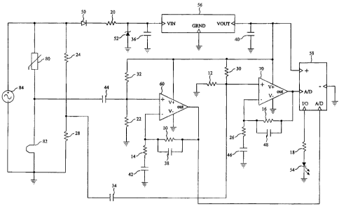
[0019] Fig. 1 is a schematic diagram illustrating an exemplary embodiment of
the present
invention;
CA 02577639 2007-02-07
[0020] Fig. 2 is a plot illustrating examples of input and output signals of a
first
amplifier, wherein the input signal is a function of the MOV current in
accordance
with an exemplary embodiment of the present invention;
[0021] Fig. 3 is a plot illustrating examples of input and output signals of a
second
amplifier, wherein the input signal is a function of the applied line voltage
in
accordance with an exemplary embodiment of the present invention; and
[0022] Fig. 4 is a flowchart illustrating an exemplary method for determining
an
expected life of an electric surge protection component and alerting an end
user near
the end of the expected life of the component in accordance with an exemplary
embodiment of the present invention.
DETAILED DESCRIPTION OF THE EXEMPLARY EMBODIMENTS
[0023] The present invention comprises a system and method for measuring
preferably each surge that a surge protection component experiences to
determine
current magnitude and current duration. As the values are measured, the system
and
method generates a cumulative surge measurement history for each component for
analysis. Based upon the analysis of the cumulative surge measurement history,
the
system and method determines an expected life of the component, and an end
user is
alerted at or preferably near an end of the expected life of the component.
Prediction
variables, such as voltage reductions between the surge measurement history
and
recently measured values, can be used in the analysis to determine the
expected life of
the component.
[0024] Specifically, in accordance with an embodiment of the present
invention,
the effective life of a surge suppression device, such as an MOV, can be
determined
using a combination of measured surge current amplitudes and duration. As
noted
above, MOVs and similar devices tend to wear down with each transient voltage
event until they eventually fail. NEMA and ANSI/IEEE standards specify typical
surge source waveforms, but do not specify joule ratings because energy
absorption
characteristics of a surge protection device are best defined and evaluated
using data,
6
CA 02577639 2010-03-15
for example, "Maximum Surge Current Capability" data, as provided for a
typical
MOV device as illustrated in Table 1, by way of example. Hence, a typical MOV
manufacturer's supplied data can include the following exemplary values of
Table 1.
The following data are examples of values for a MOV manufactured by Maida
Development Co., of Hampton, Virginia.
TABLE 1
Maximum Surge Current For Surge Current For Surge Current Surge Voltage
Number Of Maximum Number Maximum For For Surge Current
Impulses Of Impulses Number Of Maximum
Impulses Number Of MOV: 20 mm,
MOV: 20 mm, 250 Impulses 250 VAC
VAC 8us/20us current 8us/20us pulse
Impulse Width = 30 us impulses at a 1 I Ous/1000us impulses
minute current
impulse repetition impulses at a 1
rate minute
impulse
repetition rate
1 6,300A 10,000A[5,300A 300A[135A] 1200V
2 4,700 A 7,300 A 240 A 910V
2,400A 3,700A[3,100A] 160A[90A] 880V
100 950A 1200A[1300A 81A 53A] 730V
1,000 400A 530A[680A] 42A[32A] 660V
10,000 150A 200A[205A] 22A [20 A] 610V
100,000 96A 73A [130 A -[I I A 580V____~
1,000,000 25A 30A [66A] J 7.2A] 530V
[0025] Other factors should also be considered. Pulse shape, for example,
comparing column three for 8us/20us impulses with column four for lOus/1000us
impulses, makes a significant difference in the current values which can be
tolerated
by a MOV for a given maximum number of impulses.
[0026] Such surges can result from any number of sources, such as lightning.
The
following lightning parameters are disclosed in the text "Advanced Protection
Technologies - Technical Reference 96-01", at page 2, and entitled "Facts
About
Lightning: Some Of The Physics And Effects Of A Lightning Strike", the
relevant
disclosure of which may be referred to for further details. As noted by the
reference,
80% of lightning strikes are 2 or more strokes (impulses). Additionally, 50%
of
7
CA 02577639 2007-02-07
lightning strikes are 5-6 strokes (impulses), and the time between strokes
(impulses)
can vary from 100us to 10,000us.
[0027] In the conventional MOV, surge protection ratings drop to 60% to 75% of
the maximum rating for each multiple stroke (impulse) lightning strike. This
is due to
the fact that the temperature rises to 800 C to 1000 C for example, in
isolated hot
spots in the MOV volume, resulting in failures from punctures of the zinc
oxide
material.
[0028] Additional complexities are introduced when other sources, such as
internal building impulses due to motors, generators and other types of
equipment, are
considered. In consideration of all the various sources, UL 943 device tests,
for
example, require 6,000V-500A, and 6,000V-3,000A surge tests. These
requirements
are derived from ANSI/IEEE 62.41 and correspond to maximum levels based on
"medium exposure". Category B3 Ringwave (6,000V, 500A) and Category B3
Impulse (6,000A, 3,000A) levels are lower than those required (Category C) for
the
building service entrance, and are for devices within the building.
[0029] In accordance with an embodiment of the present invention, a system and
method can be provided wherein MOV current and current duration are measured
and
mapped or converted into an equivalent number of 8us/20us impulses. Additional
details of mapping values are disclosed in Maida Catalog page 13, entitled
"Peak
Current Rating As A Percentage Of Single Pulse (8 X 20 us) Value vs. Pulse
Duration". The cumulative elapsed "MOV Life" can then be accumulated in terms
of
the equivalent number of 8us/20us impulses. The number of variables involved
in this
technique, as well as the limited accuracy resulting from these variables and
the
significant test data that would need to be generated, make this approach not
entirely
cost-effective for a commercial or industrial receptacle surge protection
device.
[0030] A more cost-effective and preferred alternate approach according to
exemplary embodiments of the present invention is to provide a system and
method to
measure the MOV clamp voltages when impulses occur. Some leading sources
consider a surge protection device to have failed when the clamp voltage is
below
10% of the initial clamp voltage. As MOVs degrade, the clamp voltage decreases
8
CA 02577639 2007-02-07
because less metal oxide substrate is available in the MOV. Eventually, a
degraded
MOV will try to clamp the peak of the normal sinusoid. When it does, it will
typically
go into thermal runaway, short circuit and then fail in an open state. A
history of
transient MOV voltages and coincident current impulses can be measured and
retained in a memory. Peak line voltage measurements can be obtained using
substantially the same circuit that is used to measure transient MOV voltages
and
current impulses. The values can be stored in a database and used by a
microcontroller to generate a cumulative surge measurement history (for
example, a
rolling time window of history) for each component for analysis to determine
an
expected life of the component, and an end user can then be alerted at or
preferably
near an end of the expected life.
[0031] A current sensor (e.g., a Ragowski coil or current sensing shunt) can
be
provided to sense the transient currents through the MOV. Current sensor self-
heating
effects can be compensated for by the microcontroller through hardware or
software
used for analysis. A visual indicator, such as a steady green LED indication,
can be
provided to indicate power on and denote that the MOV is operating within a
normal
life cycle. When the MOV clamp voltage has degraded by, for example, a fixed
number of increments of 10% or to within a percentage (e.g., 15%) of the line
voltage
peak, a flashing red LED can be provided to indicate that the MOV is at or
near an
end of life. In a similar fashion, a yellow LED can be provided and flashes
when the
MOV clamp voltage is within a percentage (e.g., 30%) of the line voltage peak.
[0032] Fig. 1 is a schematic illustrating an exemplary embodiment of the
present
invention for measuring and storing a history of transient MOV voltages and
coincident current impulses in a memory. Peak line voltage measurements are
obtained using substantially the same circuit that is used to measure
transient MOV
voltages and current impulses. The values are stored in a database and used by
the
microcontroller to generate a cumulative surge measurement history for the MOV
to
determine an expected life of the MOV.
[0033] The circuit of Fig. I comprises resistors 10 through 32, capacitors 34
through 48, and diodes 50 through 54. Diode 52 is provided as a Zener diode,
and
9
CA 02577639 2007-02-07
diode 54 is provided as a light emitting diode (LED) that can provide any of a
red,
green, or yellow signal, but is not limited thereto. The circuit of Fig. I
further
comprises a voltage regulator 56, a microcontroller 58, and amplifiers 60 and
70,
wherein the LED 54 is electrically coupled between the microcontroller 58 and
ground to provide a user alert as described in greater detail below.
[0034] The surge suppression device to be monitored in the exemplary
embodiment is shown as varistor (MOV) 80. Although a varistor is shown, the
present invention is not limited thereto. A current sensor 82 is electrically
coupled in
series with the MOV 80, and resistors 24 and 28 are electrically coupled in
parallel
with the MOV 80 and sensor 82 as a voltage divider. A voltage 84 (e.g., 120V)
is
also shown electrically coupled in parallel with the MOV 80 and the sensor 82,
and
can comprise any number of electrical sources from which surges can occur. The
series coupling between the MOV 80 and the sensor 82 is electrically coupled
to the
noninverting (+) input terminal of amplifier 60 via capacitor 44. The series
coupling
between resistor 24 and resistor 28 is electrically coupled to the
noninverting (+) input
terminal of amplifier 70 via capacitor 34.
[0035] The amplifiers 60 and 70 comprise bandpass amplifiers, wherein the
input
of amplifier 60 is DC biased by resistors 22 and 32. The amplifier 60 is
bandpass
filtered by capacitor 38 in parallel with resistor 10, and capacitor 42 in
series with
resistor 14. The ground terminals V- of amplifiers 60 and 70 are electrically
connected to circuit ground, and terminals V+ of amplifiers 60 and 70 are
electrically
coupled to the VOUT terminal of the voltage regulator 56, described in greater
detail
below.
[0036] The amplifier 70 is DC biased by resistors 12 and 30, and is bandpass
filtered by capacitor 48 in parallel with resistor 16, and capacitor 46 in
series with
resistor 26. Further, the output terminal of amplifier 60 is electrically
coupled to one
of two A/D inputs of the microcontroller 58, and provides current peak and
duration
information to the microcontroller 58 as shown in greater detail in FIG. 2.
The output
terminal of amplifier 70 is electrically coupled to the second A/D input of
the
microcontroller 58, and provides voltage peak and duration information to the
CA 02577639 2010-03-15
microcontroller 58 as shown in greater detail in FIG. 3. The 110 terminal of
the
microcontroller 58 is electrically coupled to the LED 54 via resistor 18. The
microcontroller 58 is also electrically coupled to the regulator voltage
(VOUT)
terminal of voltage regulator 56. The VOUT terminal of the voltage regulator
56 is
stabilized via capacitor 40.
[0037] The input voltage (VIN) terminal of the voltage regulator 56 is half-
wave
rectified by diode 50 and current limited by resistor 20. The input voltage
(VIN)
terminal of the voltage regulator 56 is input voltage limited by Zener diode
52 and
filtered by capacitor 36. The ground (GRD) terminal of the voltage regulator
56 is
electrically connected to circuit ground. In yet another embodiment of the
present
invention, amplifiers 60 and 70, and microcontroller 58 can be incorporated
into a
single PSOC chip.
[0038] An exemplary operation of the circuit of Fig. 1 in accordance with an
embodiment of the present invention will now be described in greater detail.
Fig. 4 is
a flowchart illustrating an exemplary method for determining an expected life
of an
electric surge protection component and alerting an end user near the end of
the
expected life of the component in accordance with an exemplary embodiment of
the
present invention. In Fig. 1, as the MOV 80 degrades, the clamp voltage
decreases
because less metal oxide substrate is available in the MOV 80. Eventually, the
MOV
80 will try to clamp the peak of the normal sinusoid of the voltage 84. When
it does, it
will typically go into thermal runaway, short circuit, and then fail in an
open state. In
a first step 402, as the MOV 80 degrades, a history of transient MOV 80
voltages and
coincident current impulses are measured and retained in a memory of the
microcontroller 58 or a separately provided memory (not shown). To do so, the
microcontroller 58 is provided inputs from the amplifiers 60 and 70.
TM
[0039] The voltage regulator 56 is a low dropout regulator, such as a MCP1700,
manufactured by Microchip Technology, of Chandler, Arizona. The voltage
regulator
56 VOUT supplies power to each of the amplifiers 60, 70 and the
microcontroller 58.
The amplifier 60 is coupled to one lead of the MOV 80, and outputs a signal to
the
microcontroller 58 in step 404 that is representative of the transient current
passed by
11
CA 02577639 2007-02-07
the MOV 80. As known to those skilled in the art, at low voltages, the MOV 80
has a
high resistance. However, at or above clamping voltage values, the MOV 80 has
a
low resistance resulting in current flow detected by the amplifier 60, and
which
generates a signal input to the microcontroller 58. In FIG. 2, an example of
input and
output signals of the amplifier 60 are shown. In FIG. 2, an exemplary input
signal at
the noninverting (+) terminal of the amplifier 60 is shown at plot (a), and an
output
signal of the amplifier 60 is shown at plot (b). The output of plot (b) can
then be used
to determine the current peak (Ipk) and the current peak duration in step 406.
[0040] For comparison purposes, the voltage divider of resistors 24 and 28
provides a reduced amplitude replica of the line voltage transient to the
amplifier 70
which generates a signal input to the microcontroller 58 in step 408 that is
representative of the transient input signal levels. In FIG. 3, an example of
input and
output signals of the amplifier 70 are shown. These signals can be used to
detect
peak signal levels and duration. In FIG. 3, an exemplary input signal at the
noninverting (+) terminal of the amplifier 70 is shown at plot (a), and an
output signal
of the amplifier 70 is shown at plot (b). The output of plot (b) can then be
used to
determine the clamped voltage peak (Vpk) and the voltage peak duration at step
410.
[0041] The microcontroller 58 receives the signals of amplifiers 60 and 70,
and
can therefore monitor preferably each surge experienced by the surge protector
MOV
80. The microcontroller 58 can further be programmed to maintain a database
comprised of preferably each surge experienced by the surge protector MOV 80,
and
can generate a cumulative history to determine the remaining life of the MOV
80 at
step 412. Specifically, in step 412 the microcontroller 58 monitors preferably
each
surge that MOV 80 experiences. Each surge is measured to determine current
magnitude and current duration, and a cumulative surge measurement history is
maintained for the MOV 80. Voltage reductions between the surge measurement
history and recently measured values are then used to determine the expected
life of
the MOV 80. If it is determined that the MOV 80 is near the end of an expected
life,
notice is provided at step 414. If it is determined that the MOV 80 is not
near the end
of an expected life, the method returns to step 402.
12
CA 02577639 2007-02-07
[0042] The hardware and/or software of the microcontroller 58 can be provided
with any number of algorithms to generate warnings based on input values, and
thereafter output signals to the LED 54 at step 414 such that a user is
alerted at or
preferably near an end of the expected life of the MOV 80. Specifically, the
stored
cumulative surge history can be compared with recently measured values at step
412
to determine a remaining life of the MOV 80. In yet other embodiments of the
present invention, the microcontroller 58 can look for predetermined voltage
reductions to determine if the MOV 80 is near the end of an expected life. In
still
other embodiments of the present invention, the microcontroller 58 can look
for a
specific count of input signals exceeding a threshold level to determine if
the MOV 80
is near the end of an expected life.
[0043] As noted above, if it is determined that the MOV 80 is near the end of
an
expected life, notice is provided at step 414 to the LED 54. For example, one
steady
green LED indication can be used to indicate power on and that the MOV 80 is
operating within the range of a normal life cycle. When the single MOV 80
clamp
voltage has degraded to within 15% of the peak line voltage for example, a red
LED
indication can begin flashing to indicate that the MOV 80 is at or near an end
of life.
Additionally, when the single MOV 80 has experienced a predetermined number of
defined surge levels, a red LED indication can begin flashing to indicate that
the
MOV 80 is at or near an end of life. As noted above, the peak line voltage
measurements are available using the same circuit that is used to measure
transient
MOV 80 voltages and current impulses, hence typical and maximum line voltages
can
be determined and used with any number of suitable algorithms to determine the
near
end of life point of the MOV 80.
[0044] In yet another embodiment of the present invention, when the clamp
voltage is at some percentage above AC line voltage peaks, a red LED
indication can
begin flashing. In yet another embodiment of the present invention, a yellow
LED
indication can be used to indicate the time between when the MOV 80 clamp
voltage
has degraded by some value, for example, 10%, and when the MOV 80 clamp
voltage
has degraded to some value above line voltage peaks. Obviously many other
warning
13
CA 02577639 2007-02-07
variations are possible to visually or audibly indicate where the product is
in the MOV
80 life cycle.
[0045] In yet another embodiment of the present invention, the sensitivity of
the
current sensor 82 and the values of resistors 24 and 28 can be adjusted to
provide
signals to the microcontroller 58 directly, without requiring amplifiers 60
and 70.
[0046] While a number of exemplary embodiments have been chosen to illustrate
the present invention, it will be understood by those skilled in the art that
various
changes and modifications can be made therein without departing from the scope
of
the invention as defined in the appended claims.
14