Note: Descriptions are shown in the official language in which they were submitted.
CA 02577713 2007-02-16
SF-1232
1
DESCRIPTION
REACTION APPARATUS OF THE CHLOROSILANES
TECHNICAL FIELD
[0001]
The present invention relates to a reaction apparatus of the
chlorosilanes for reacting the chlorosilanes by supplying the
chlorosilanes and hydrogen to a tubular reaction vessel from a gas
supply port formed on an upper side of the reaction vessel made
of a carbon material and by making the chlorosilanes and hydrogen
to come into contact with an inside face to which silicon has
deposited for the reaction vessel heated up to at least a temperature
at which a reaction occurs.
BACKGROUND ART
[0002]
Conventionally, many kinds of methods of manufacturing
silicon that is used as a raw material of a semiconductor and a
solar battery for power generation have been known. Some of the
above methods have already been implemented industrially.
For instance, one of above methods is called a siemens method.
In this method, a silicon rod that has been heated up to a deposition
temperature of silicon by energizing is disposed in a bell jar,
CA 02577713 2007-02-16
SF-1232
2
and trichlorosilane (SiHC13) and monosilane (SiH4) are made to come
into contact with the silicon rod together with a reducing gas such
as hydrogen to deposit silicon.
[0003]
This method, by which high purity silicon can be obtained,
is implemented industrially as a general method. However, since
silicon is deposited in a batch system, it is necessary to repeat
for each batch a series of processes such as installing of a silicon
rod that is a seed, energizing, heating, depositing, cooling, and
extracting of the silicon rod, and cleaning of the bell jar, thereby
requiring complicated operations.
On the other hand, as a method capable of continuously
manufacturing polycrystal silicon, a method using an apparatus
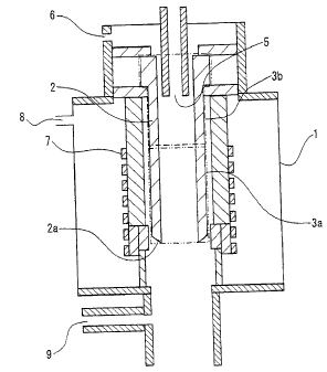
shown in Fig. 1 is proposed (see Patent documents 1 and 2). This
silicon manufacturing apparatus is provided with a reaction vessel
2 made of a carbon material, a raw gas supply port 5 that is disposed
on an upper side of the reaction vessel 2 and that supplies the
chlorosilanes and hydrogen into the reaction vessel 2, and a high
frequency heating coil 7 disposed on the periphery of the reaction
vessel 2 in a closed container 1.
[0004]
The reaction vessel 2 is heated by an electromagnetic wave
emitted from the high frequency heating coil 7 disposed on the
periphery thereof. A section from a bottom end portion 2a of the
CA 02577713 2007-02-16
SF-1232
3
reaction vessel 2 to a specified height (a region enclosed by the
alternate long and two short dashes line in the figure: reaction
portion 3a) is heated up to a temperature at which silicon can be
deposited.
The chlorosilanes supplied from the raw gas supply port 5 is
made to come into contact with the heated inside face of the reaction
vessel 2 to deposit silicon to the inside face of the reaction
portion 3a.
[0005]
In the apparatus shown in the figure, the reaction portion
3a is heated up to a temperature less than a melting point of silicon
at which silicon can be deposited, and silicon is deposited in a
solid state. The reaction portion 3a is then heated up to a
temperature equivalent to or higher than a melting point of silicon,
and the part or whole of a deposited substance is molten, dropped
from an opening of the bottom end portion 2a, and recovered in a
cooling recovery chamber (not shown) disposed in a dropping
direction.
Moreover, there is another method in which the inside face
of the reaction vessel 2 is heated up to a temperature equivalent
to or higher than a melting point of silicon to deposit silicon
in a molten state, and a silicon molten solvent is continuously
dropped from an opening of the bottom end portion 2a of the reaction
vessel 2 and is recovered.
CA 02577713 2007-02-16
SF-1232
4
[0006]
Since a silicon deposition in a region other than the inside
face of the reaction vessel 2 in the closed container 1 causes an
operation to be prevented, the sealing gas supply port 8 for
supplying a sealing gas such as hydrogen and an inert gas is formed
for instance at a region in which silicon must be prevented from
being deposited, such as a region around the bottom end portion
2a of the reaction vessel 2, in order to prevent a silicon
deposition.
Moreover, an apparatus similar to one shown in Fig. 1 is used
for other applications as a reaction apparatus of the chlorosilanes
for reacting the chlorosilanes and hydrogen by a hydrogen reducing
reaction. For instance, an apparatus similar to one shown in Fig.
1 is used for reducing silicon tetrachloride to trichlorosilane
in order to recover a raw gas for manufacturing polycrystalline
silicon.
[0007]
Even in this case, silicon is deposited to the reaction
portion 3a heated up to a temperature at which a hydrogen reducing
reaction occurs by an electromagnetic wave emitted from the high
frequency heating coil 7. Silicon tetrachloride is then reduced
to trichlorosilane by making silicon tetrachloride and hydrogen
that have been supplied from the raw gas supply port 5 to come into
contact with an inside face of the reaction portion 3a to which
CA 02577713 2007-02-16
SF-1232
silicon has deposited. A gas after the reaction is recovered in
a portion outside the closed container 1 through an opening of the
bottom end portion 2a of the reaction vessel 2.
5 Patent document 1: Japanese Laid-Open Patent Publication No.
2003-2627
Patent document 2: Japanese Laid-Open Patent Publication No.
2002-29726
DISCLOSURE OF THE INVENTION
PROBLEMS TO BE SOLVED BY THE INVENTION
[0008]
In a silicon manufacturing apparatus as shown in Fig. 1, a
reaction vessel 2 is made of a carbon material. Silicon coats a
carbon face of the inside face of the reaction portion 3a, or a
silicon carbide film formed by a reaction between silicon and carbon
coats the carbon face. However, a perforated carbon face is exposed
on a non reaction portion 3b (a region enclosed by the alternate
long and short dash line in the figure) on the upper side of the
reaction portion 3a.
[0009]
Since the chlorosilanes such as trichlorosilane is a molecule
having an extremely large viscous resistance, a person with an
ordinary skill in the art has never thought conventionally that
CA 02577713 2007-02-16
SF-1232
6
such the chlorosilanes penetrate a pipe wall at the non reaction
portion 3b of the reaction vessel 2 and leak externally. In practice,
such a phenomenon has never occurred conventionally.
However, in the case in which a mole ratio of hydrogen in a
raw gas is increased, trichlorosilane is effectively decomposed
and a deposition efficiency of silicon is improved. Therefore, in
the case in which a mole ratio of hydrogen to trichlorosilane was
increased and an amount of hydrogen exceeded a certain mole ratio,
there was a phenomenon in which trichlorosilane together with
hydrogen penetrated a pipe wall of the reaction vessel to leak
externally.
[0010]
In a silicon manufacturing apparatus described above, by
shortening an inner diameter of the reaction vessel at the
intermediate section and by making an internal shape of the reaction
vessel complicated, a gas flow resistance change section such as
an orifice and a curved pipe portion is formed in the reaction vessel,
and a differential pressure is set between an inlet on the upper
side and an outlet on the bottom end portion side in the reaction
portion (a numeral 3a in Fig. 1), thereby improving a contact
efficiency of a raw gas and accelerating a reaction.
[0011]
However, in many cases, the above phenomenon in which the
chlorosilanes such as trichlorosilane together with hydrogen
CA 02577713 2007-02-16
SF-1232
7
penetrates a pipe wall of the reaction vessel to leak externally
occurs in the case in which a differential pressure is applied inside
the reaction vessel in particular.
In the case in which the chlorosilanes supplied to the
reaction vessel penetrate a pipe wall and leak externally, an
outside face of the reaction vessel and a heat insulating member
installed outside the reaction vessel are deteriorated. In addition,
in some cases, silicon is deposited to other members and
apparatuses.
[0012]
The present invention was made in order to solve the above
described problems. An object of the present invention is to provide
a reaction apparatus of the chlorosilanes sufficiently capable of
suppressing that a raw gas such as the chlorosilanes supplied into
the reaction vessel penetrates a pipe wall of the reaction vessel
to leak externally.
MEANS FOR SOLVING THE PROBLEMS
[0013]
A reaction apparatus of the chlorosilanes related to the
present invention for supplying the chlorosilanes and hydrogen to
a reaction vessel from a gas supply port formed on an upper side
of the reaction vessel made of a carbon material, for heating a
reaction portion that is a section from the bottom end portion to
CA 02577713 2007-02-16
SF-1232
8
a specified height in the reaction vessel and that has an inside
face to which silicon has deposited, up to at least a temperature
at which a reaction occurs, and for reacting the chlorosilanes by
making the chlorosilanes and hydrogen to come into contact with
the inside face of the reaction portion, is characterized in that
a gas penetration preventing processing for preventing the
chlorosilanes supplied to the reaction vessel from penetrating a
pipe wall of the reaction vessel is carried out to the inside face
and/or the outside face of the non reaction portion on the side
upper than the reaction portion in the reaction vessel.
[0014]
It is preferable that a gas penetration coefficient from the
inside face to the outside face of the reaction vessel at the non
reaction portion is 1 x 10⁻³ cm2/S or less.
EFFECT OF THE INVENTION
[0015]
According to a reaction apparatus of the chlorosilanes
related to the present invention, it can be sufficiently suppressed
that a raw gas such as the chlorosilanes supplied into the reaction
vessel penetrates a pipe wall of the reaction vessel and leaks
externally.
BRIEF DESCRIPTION OF THE DRAWINGS
CA 02577713 2007-02-16
SF-1232
9
[0016]
Fig. 1 is a cross-sectional view showing a silicon
manufacturing apparatus for supplying the chlorosilanes and
hydrogen from a gas supply port formed on an upper side of a reaction
vessel made of a carbon material and for depositing silicon to the
inside face of the reaction vessel heated.
Fig. 2 is a view for illustrating a measuring apparatus of
a gas penetration coefficient.
EXPLANATIONS OF LETTERS OR NUMERALS
[0017]
1: closed container
2: reaction vessel
2a: bottom end portion
3a: reaction portion
3b: non reaction portion
5: raw gas supply port
6: raw gas supply port
7: high frequency heating coil
8: sealing gas supply port
9: gas exhaust port
21: flange
22: carbon plate
23: chamber
CA 02577713 2007-02-16
SF-1232
24: pressure gage
BEST MODE FOR CARRYING OUT THE INVENTION
[0018]
5 An embodiment (example) of the present invention will be
described below in detail with reference to the drawings. While
the present invention can be applied to a reaction apparatus of
the chlorosilanes having a similar apparatus configuration in
addition to a silicon manufacturing apparatus shown in Fig. 1, for
10 instance, to a reducing furnace of silicon tetrachloride, the
following describes an example in which the present invention is
applied to a silicon manufacturing apparatus.
The silicon manufacturing apparatus shown in Fig. 1 is
provided with a tubular reaction vessel 2 in a closed container
1. By supplying the chlorosilanes from a raw gas supply port 5
disposed on an upper side of the reaction vessel 2, silicon is
deposited on the inside wall of the reaction vessel 2 that has been
heated by a high frequency heating coil 7.
[0019]
As the chlorosilanes that are used for a reaction, there are
mentioned, for instance, trichlorosilane (SiHC13, hereafter
referred to as TCS) and silicon tetrachloride (SiCl4, hereafter
referred to as STC) . In addition, there can be preferably used the
chlorodisilanes such as dichlorosilane (SiH2Clz), monochlorosilane
CA 02577713 2007-02-16
SF-1232
11
(SiH3Cl) , and hexachlorodisilane (Si2C16) , and the chlorotrisilanes
such as octachlorotrisilane (Si3C18) . While such the chlorosilanes
can be individually used, at least two kinds of chlorosilanes can
also be combined to be used.
[0020]
Hydrogen that is used for a deposition reaction together with
the chlorosilanes is supplied from, for instance, a raw gas supply
port 5 or a separate raw gas supply port 6.
The reaction vessel 2 is made of a carbon material such as
graphite, which can be heated by a high frequency and has a
resistance at a melting point of silicon. The reaction vessel 2
is formed cylindrically for instance, and is disengaged downward
from an opening of the bottom end portion 2a.
[0021]
A shape of an opening at the bottom end portion 2a of the
reaction vessel 2 can be straight downward or tapered to form a
reduced or enlarged portion in such a manner that a diameter at
a lower section is smaller or larger. A peripheral edge of the
opening can be horizontal, inclined, or in a wave shape. By such
a configuration, a silicon droplet can be easily dropped from the
peripheral edge of the opening, a droplet of a silicon molten solvent
can be uniformed, and a particle diameter of a silicon particle
can be uniformly adjusted to be smaller.
[0022]
CA 02577713 2007-02-16
SF-1232
12
The reaction vessel 2 is heated by an electromagnetic wave
(a high frequency wave) emitted from the high frequency heating
coil 7 disposed on the periphery thereof. An inside face of a region
from a bottom end portion 2a of the reaction vessel 2 to a specified
height (a region enclosed by the alternate long and two short dashes
line in the figure: reaction portion 3a) is heated up to a
temperature less than a melting point of silicon (approximately
1410 to 1430 C), at which silicon can be deposited. A heated
temperature of the reaction portion 3a is preferably 950 C or higher,
more preferably 1200 C or higher, further preferably 1300 C or
higher.
[0023)
For silicon that has been deposited on the inside face of the
reaction vessel 2, after silicon is deposited in a solid state on
the inside face of the reaction portion 3a of the reaction vessel
2, the inside face is heated up to a temperature equivalent to or
higher than a melting point of silicon, and the part or whole of
a deposited substance is molten, dropped from an opening of the
bottom end portion 2a, and recovered in a cooling recovery chamber
(not shown) disposed in a dropping direction.
Moreover, it is also possible that the reaction portion 3a
of the reaction vessel 2 is heated up to a temperature equivalent
to or higher than a melting point of silicon, silicon is deposited
in a molten state to the inside face thereof, and a silicon molten
CA 02577713 2007-02-16
SF-1232
13
solvent is continuously dropped from an opening of the bottom end
portion 2a of the reaction vessel 2 and is recovered.
[0024]
In general, the reaction portion 3a is a section with a length
in the range of 30 to 90% of the total length of the reaction vessel
2 in the closed container 1. In order to prevent silicon from being
deposited to the raw gas supply port 5 or the like, a section from
the top edge with a length of 10% or more of the total length of
the reaction vessel 2 in the closed container 1 is the non reaction
portion 3b (a region enclosed by the alternate long and short dash
line in the figure) in which silicon is not deposited. In the case
in which the reaction vessel 2 is lengthened, the non reaction
portion 3b is shortened relatively.
[0025]
The high frequency heating coil 7 generates an
electromagnetic wave to heat the reaction vessel 2 by energizing
a coil from a power source (not shown). A frequency of the
electromagnetic wave can be set to a proper value depending on a
material or a shape of an object to be heated such as the reaction
vessel 2, for instance, to a value in the range of several tens
Hz to several tens GHz.
As a method of heating the reaction vessel 2 from the outside,
there are mentioned a method using a heating wire and a method using
infrared rays, in addition to a high frequency heating method.
CA 02577713 2011-05-02
14
[0026]
Silicon dropped into the cooling recovery section is cooled
by a solid coolant such as silicon, copper, and molybdenum, a liquid
coolant such as liquid silicon tetrachloride and liquid nitrogen,
or a cooling gas supplied from a cooling gas supply port if
necessary.
Moreover, in such a manner that silicon can be more
effectively cooled, a cooling jacket can be formed on the cooling
recovery chamber, and cooling medium liquid such as water, thermal
oil, and alcohol can pass through the cooling jacket for cooling.
As a material of the cooling recovery chamber, there can be used,
for instance, a metal material, a ceramics material, and a glass
material. In such a manner that high-purity silicon can be recovered
as well as this apparatus can be made firm as an industrial apparatus,
it is preferable to carry out lining to the inside of the metal
recovery chamber by using silicon, Teflon (registered trademark),
a quartz glass or the like. It is also possible to dispose silicon
particles at the bottom of the cooling recovery chamber. After a
reaction, an exhaust gas in the reaction vessel 2 is exhausted
from a gas exhaust port 9. If necessary, it is also possible to
form an ejecting port for ejecting solidified silicon continuously
or intermittently from the cooling recovery chamber.
[0027]
Since a trouble in an apparatus operation occurs in the case
CA 02577713 2007-02-16
SF-1232
in which silicon is deposited to a region other than the reaction
portion 3a, such as a region around the bottom end portion 2a of
the reaction vessel 2, and a gap between the reaction vessel 2 and
a gas supply pipe forming the raw gas supply pipe 5, the sealing
5 gas supply ports 6 and 8 or the like for supplying a sealing gas
are formed at a region in which silicon must be prevented from being
deposited in the closed container 1 in such a manner that the region
is filled with a sealing gas atmosphere.
As a sealing gas, it is preferable to use a gas that does not
10 generate silicon and that does not affect a generation of silicon
in a region in which the chlorosilanes exist. More specifically,
hydrogen or an inert gas such as argon and helium can be used.
[0028]
Moreover, by introducing into a reaction system a reaction
15 sample agent that can react to solid silicon deposited to a
low-temperature section in the reaction system and by reacting
silicon to the reaction sample agent, there can be avoided a problem
that solid silicon is deposited to a nozzle portion or the like
in the reaction system and chokes up the nozzle portion. As a
reaction sample agent that can react to silicon, there can be
mentioned for instance hydrogen chloride (HC1) and silicon
tetrachloride.
[0029]
The manufacturing conditions of the silicon manufacturing
CA 02577713 2007-02-16
SF-1232
16
apparatus shown in Fig. 1 are not restricted. However, it is
preferable to determine a supply ratio, a supply amount, and a
staying time of the chlorosilanes and hydrogen in such a manner
that the chlorosilanes and hydrogen are supplied to the silicon
manufacturing apparatus to generate silicon under the condition
in which a conversion rate from the chlorosilanes to silicon is
20% or higher, preferably 30% or higher.
In order to obtain a silicon manufacturing speed economical
against a size of the reaction chamber, a molar fraction of the
chlorosilanes in a supply gas is preferably in the range of 0.1
to 99.9 mole more preferably in the range of 5 to 50 mole %.
While a higher reaction pressure has an advantage of miniaturizing
an apparatus, a pressure of 0 to 1 MPaG can be easily implemented
industrially.
[0030]
While a staying time of a gas changes depending on the
conditions of a pressure and a temperature to a reaction chamber
having a constant capacity, an average staying time of a gas in
the reaction vessel 2 can be set to 0.001 to 60 seconds, preferably
0.01 to 10 seconds under the reaction condition, thereby enabling
a sufficiently economical conversion rate of the chlorosilanes to
be obtained.
In the silicon manufacturing apparatus described above, in
the non reaction portion 3b of the reaction vessel 2, in which a
CA 02577713 2007-02-16
SF-1232
17
carbon face is not coated by a silicon film or a silicon carbide
film, the chlorosilanes in the reaction vessel 2 penetrate a pipe
wall and leak externally under the specific condition.
[0031]
More specifically, a leakage of the chlorosilanes occurs in
the case in which a mole ratio of hydrogen to the chlorosilanes
in a raw gas is large. For instance, in the case in which an amount
of hydrogen to a total amount of hydrogen and the chlorosilanes
exceeds 80 mol%, a leakage of the chlorosilanes occurs.
For instance, from a view point of an effective decomposition
of the chlorosilanes and an improvement of deposition efficiency
of silicon, a mole ratio of hydrogen to the chlorosilanes (H2/SiHC13)
is preferably in the range of 5 to 30, more preferably in the range
of 10 to 20. However, in such a range of a mole ratio, the
chlorosilanes penetrate a pipe wall of the non reaction portion
3b and leak externally in some cases.
[0032]
In particular, in many cases, a leakage of the chlorosilanes
occurs in the case in which a differential pressure is applied inside
the reaction vessel 2 when a mole ratio of hydrogen is in the above
range.
In a silicon manufacturing apparatus as shown in Fig. 1, in
some cases, by shortening an inner diameter of the reaction vessel
2 at the intermediate section and by making an internal shape of
CA 02577713 2007-02-16
SF-1232
18
the reaction vessel 2 complicated, a gas flow resistance change
section is formed in the reaction vessel 2, and a differential
pressure is set between an inlet on the upper side and an outlet
on the bottom end portion 2a side in the reaction portion 3a, thereby
improving a contact efficiency of a raw gas and accelerating a
reaction.
[0033]
However, in the case in which an amount of hydrogen to a total
amount of hydrogen and the chlorosilanes exceeds 80 mol% and the
above differential pressure in the reaction vessel exceeds 10 kPa,
the chlorosilanes easily penetrate a pipe wall of the non reaction
portion 3b and leak externally.
In the present invention, in order to prevent a gas of the
chlorosilanes from penetrating a pipe wall of the non reaction
portion 3b and leaking externally under the reaction condition as
described above, a processing for preventing a gas penetration is
carried out to the non reaction portion 3b. The following describes
a specific method of the gas penetration preventing processing.
[0034]
In a first method, a gas penetration is prevented by forming
a coating film on the surface of the non reaction portion 3b. As
a coating film, a high melting point metal such as tungsten,
molybdenum, and silicon, ceramics such as silicon carbide, silicon
nitride, and boron nitride, and pyrolytic carbon are preferable.
CA 02577713 2007-02-16
SF-1232
19
A publicly known method can be used to form a coating film
on the surface of a carbon material. As a specific example thereof,
there are mentioned a thermal spraying method, a chemical vapor
deposition (CVD), and a coating of a molten solvent, which can be
properly selected depending on a material for forming a coating
film. The thermal spraying method is preferable in the case in which
a material such as a high melting point metal is used as a coating
film, and the CVD is preferable in the case in which a material
such as ceramics and pyrolytic carbon is used as a coating film.
[0035]
In the case in which a coating film of silicon is formed, as
a preferable method other than the above methods, there can be
mentioned a method in which a mixed gas of the chlorosilanes and
hydrogen is made to come into contact with the surface of a carbon
material and silicon is deposited at a temperature equivalent to
or higher than a silicon generation temperature (approximately
500 C), preferably a temperature equivalent to or less than a
melting temperature of silicon.
In the case in which a coating film is formed by silicon,
silicon carbide is generated on an interface of the coating film
due to a reaction between silicon and carbon. Since the silicon
carbide also acts as a coating film, the coating film can be used
without problems.
[0036]
CA 02577713 2007-02-16
SF-1232
In a second method, a fine grain with a size that can choke
up minute holes in a carbon material of the reaction vessel 2 is
coated on the carbon material. Such a fine grain is not restricted
in particular in the case in which an elimination of the fine grain
5 caused by decomposition or evaporation does not occur under the
usage environment. As a fine grain that can be easily obtained
industrially, there can be mentioned for instance a carbon fine
grain, a boron nitride fine grain, and a silicon oxide fine grain.
As a method of coating, there can be mentioned for instance
10 a method in which the above fine grain is dispersed in a suitable
dispersion medium such as an organic solvent and a resin solution
to make a state of dispersion liquid, and the dispersion liquid
is made to adhere to the surface of the carbon material by a method
such as a brush coating and a spraying, and a method in which the
15 carbon material is immersed in the dispersion liquid.
[0037]
After the fine grain dispersion liquid is coated on the carbon
material, the dispersion medium is eliminated by natural
evaporation, evaporation caused by heating the carbon material,
20 or decomposition. In the case in which the fine grain is carbon,
it is also preferable to further heating the carbon material after
eliminating the dispersion medium and to making the fine grain to
adhere to the carbon material.
The above gas penetration preventing processing can be
CA 02577713 2007-02-16
SF-1232
21
carried out to the inside face, the outside face, or the both faces
of the non reaction portion 3b. As described above, a penetration
of a raw gas to the peripheral side of the reaction vessel 2 can
be suppressed by forming a coating face for coating a carbon face
in the non deposition portion 3b or by choking up a carbon minute
hole with a fine grain.
[0038]
In order to effectively prevent the chlorosilanes from
penetrating a pipe wall of the non reaction portion 3b and leaking
externally under the above described conditions of a mole ratio
of hydrogen and a differential pressure in the reaction vessel 2,
it is preferable to carry out the above processing in such a manner
that a gas penetration coefficient from the inside face to the
outside face of the reaction vessel 2 at the non reaction portion
3b is 1 x 10⁻³ cm2/S or less (a value obtained by a measuring method
in an embodiment described later). In the case in which a carbon
face to which the above processing is not carried out is exposed
in a reaction vessel 2, the reaction vessel 2 has a gas penetration
coefficient of 1 x 10⁻¹ cm2/S in general.
[0039]
It is preferable to carry out the above gas penetration
preventing processing to the entire of at least one of the inside
and outside faces of the non reaction portion 3b in practice.
Moreover, it is also possible to carry out the above processing
CA 02577713 2007-02-16
SF-1232
22
to at least a part of the reaction portion 3a. In particular, in
the case in which the gas penetration preventing processing is
carried out only to the outside face, it is preferable to carry
out the processing to a range as wide as possible including the
non reaction portion 3b, preferably to the entire of the outside
face.
As a prior art, it is publicly known to coat a region to which
silicon is deposited by using a material having a comparatively
high resistance as compared with a silicon molten solvent in order
to improve a resistance of the reaction vessel 2 and a purity of
a silicon product. However, this is carried out to the section in
which deposited silicon deposits to a pipe wall face depending on
a silicon deposition, and a position of a purpose and an object
is different from that of the present invention in which the
processing is carried out to the non reaction portion 3b that is
a section to which silicon is not deposited.
Examples
While the preferred examples of the present invention will
be described in the following, the present invention is not
restricted to the examples. In the following examples, a gas
penetration coefficient was measured by the following method using
an apparatus shown in Fig. 2. A carbon plate 22 related to Examples
1 to 9 and Comparative examples 1 and 2 was interposed between
CA 02577713 2007-02-16
SF-1232
23
flanges 21 made of a stainless steel, and the contact portions of
the carbon plate 22 and the flanges 21 were coated by an 0 ring
and a fluorocarbon resin paste.
[0040]
Subsequently, a chamber 23 made of a stainless steel was
filled with a nitrogen gas, and the inside of the chamber was
pressurized up to 400 kPa at a normal temperature. Since the outside
of the chamber 23 is an air open system, the following calculation
was carried out while an outside pressure was a constant value of
0 kPaG.
A pressure change in the chamber 23 was measured by a pressure
gage 24 after a pressure in the chamber 23 was started to be reduced
by passing of a nitrogen gas in the chamber 23 through a minute
hole in the carbon plate 22. While approximating a pressure
reduction speed in the chamber 23 in a unit time to a straight line,
a gas penetration amount Q was then obtained by the expression of
Q [cm 3 = Pa/s] = V x ( (P2 - P1) / (T2 - Tl)) , where V is a total volume
of the chamber 23, the pressure gage 24, and the inside of the pipe,
Pl is a pressure in the chamber 23 at time Ti after the start of
a pressure reduction (Tl is approximately 0 s) , and 22 is a pressure
in the chamber 23 at time T2 after the start of a pressure reduction.
[0041]
By using the obtained gas penetration amount Q, a gas
penetration coefficient K [cm2/s] was obtained by the expression
CA 02577713 2007-02-16
SF-1232
24
of K = Q = L / (AP = A) , where L [cm] is a gas penetration thickness
of the carbon plate 22, LP [Pa] is a differential pressure in a
thickness L of the carbon plate 22, and A [cm2] is a nitrogen gas
penetration area.
In the present embodiments, the total volume V of the chamber
23, the pressure gage 24, and the inside of the pipe was 427 cm3,
and the nitrogen gas penetration area A of the carbon plate 22 is
46.6 cm2. Since the carbon plate 22 is in a disc shape, the nitrogen
gas penetration area A is a total sum of an area of the peripheral
portion and an area of the outside faces of the disc.
(Example 1)
There was prepared a carbon plate in a disc shape that is made
of a carbon material (a product on the market, a high density
isotropic carbon with a density of 1.82 g/cm3) being used for a
reaction vessel of the above described silicon manufacturing
apparatus and that has a diameter of 60 mm and a thickness of 5
mm, and metal tungsten was thermal-sprayed to one face of the carbon
plate, thereby forming a tungsten metal film with a thickness of
1 m. For this carbon plate, a gas penetration coefficient was
measured by the above method.
[0042]
Moreover, by using a reaction vessel made of a carbon material
similar to the above (a diameter was 100 mm, an inner diameter was
CA 02577713 2007-02-16
SF-1232
70 mm, a total length was 1500 mm, and a length of the reaction
portion was 1000 mm, and a gas flow resistance change section was
formed in the vessel), a tungsten metal film with a thickness of
1 m was formed on the inside face on the side upper than the reaction
5 portion in the reaction vessel as described above, and the reaction
vessel was installed to the silicon manufacturing apparatus.
A mixed gas of trichlorosilane of 20 kg/H and hydrogen of 40
Nm3/H was then flown into the reaction vessel under the condition
in which a differential pressure was 10 kPa between an inlet on
10 the upper side and an outlet on the bottom end portion side in the
reaction portion, the reaction vessel was heated to 1500 C, and
an operation was carried out for 100 hours. After the operation,
a weight of a carbon heat insulating material (a diameter was 170
mm, an inner diameter was 100 mm, a length was 1000 mm, and a carbon
15 density was 0.16 g/cm3) installed on the outside wall of the reaction
vessel was measured, and a weight reduction speed (a heat insulating
material deterioration speed) was calculated. Table 1 shows the
measurement results of a gas penetration coefficient and a heat
insulating material deterioration speed.
(Example 2)
There was prepared a carbon plate in a disc shape that is made
of a carbon material (a product on the market, a high density
isotropic carbon with a density of 1.82 g/cm3) being used for a
CA 02577713 2007-02-16
SF-1232
26
reaction vessel of the above described silicon manufacturing
apparatus and that has a diameter of 60 mm and a thickness of 5
mm, one face of the carbon plate was heated to a silicon generation
temperature (500 C), and a silicon carbide film with a thickness
of 1 pm was formed by supplying trichlorosilane and hydrogen with
a molar fraction of 50% to the surface thereof. For this carbon
plate, a gas penetration coefficient was measured. Table 1 shows
the measurement results.
(Example 3)
There was prepared a carbon plate in a disc shape that is made
of a carbon material (a product on the market, a high density
isotropic carbon with a density of 1.82 g/cm3) being used for a
reaction vessel of the above described silicon manufacturing
apparatus and that has a diameter of 60 mm and a thickness of 5
mm, and one face of the carbon plate was made to come into contact
with molten silicon, thereby forming a silicon carbide film with
a thickness of 1 m. For this carbon plate, a gas penetration
coefficient was measured.
[0043]
Moreover, by using a reaction vessel made of a carbon material
similar to the above (a diameter was 100 mm, an inner diameter was
70 mm, a total length was 1500 mm, and a length of the reaction
portion was 1000 mm, and a gas flow resistance change section was
CA 02577713 2007-02-16
SF-1232
27
formed in the vessel), a silicon carbide film with a thickness of
1 m was formed on the inside face on the side upper than the reaction
portion in the reaction vessel as described above, and the reaction
vessel was installed to the silicon manufacturing apparatus.
A mixed gas of trichlorosilane of 20 kg/H and hydrogen of 40
Nm3/H was then flown into the reaction vessel under the condition
in which a differential pressure was 10 kPa between an inlet on
the upper side and an outlet on the bottom end portion side in the
reaction portion, the reaction vessel was heated to 1500 C, and
an operation was carried out for 100 hours. After the operation,
a weight of a carbon heat insulating material (a diameter was 170
mm, an inner diameter was 100 mm, a length was 1000 mm, and a carbon
density was 0.16 g/cm3) installed on the outside wall of the reaction
vessel was measured, and a weight reduction speed (a heat insulating
material deterioration speed) was calculated. Table 1 shows the
measurement results of a gas penetration coefficient and a heat
insulating material deterioration speed.
(Example 4)
There was prepared a carbon plate in a disc shape that is made
of a carbon material (a product on the market, a high density
isotropic carbon with a density of 1.82 g/cm3) being used for a
reaction vessel of the above described silicon manufacturing
apparatus and that has a diameter of 60 mm and a thickness of 5
CA 02577713 2007-02-16
SF-1232
28
MM, and silicon carbide was deposited on one face of the carbon
plate by a chemical vapor deposition (CVD) . For this carbon plate,
a gas penetration coefficient was measured. Table 1 shows the
measurement results.
(Example 5)
There was prepared a carbon plate in a disc shape that is made
of a carbon material (a product on the market, a high density
isotropic carbon with a density of 1.82 g/cm3) being used for a
reaction vessel of the above described silicon manufacturing
apparatus and that has a diameter of 60 mm and a thickness of 5
mm, and a carbon fine grain (a paste containing a phenol resin:
an average carbon grain diameter of 1 m, and a carbon component
rate of 20%) was coated and impregnated to one face of the carbon
plate. Subsequently, a liquid component contained in the liquid
carbon material was eliminated at a temperature of 200 C, and carbon
was heated and stuck. For this carbon plate, a gas penetration
coefficient was measured.
[0044]
Moreover, by using a reaction vessel made of a carbon material
similar to the above (a diameter was 100 mm, an inner diameter was
70 mm, a total length was 1500 mm, and a length of the reaction
portion was 1000 mm, and a gas flow resistance change section was
formed in the vessel) , the inside face on the side upper than the
CA 02577713 2007-02-16
SF-1232
29
reaction portion in the reaction vessel was processed by the liquid
carbon material as described above, and the reaction vessel was
installed to the silicon manufacturing apparatus.
A mixed gas of trichlorosilane of 20 kg/H and hydrogen of 40
Nm3/H was then flown into the reaction vessel under the condition
in which a differential pressure was 10 kPa between an inlet on
the upper side and an outlet on the bottom end portion side in the
reaction portion, the reaction vessel was heated to 1500 C, and
an operation was carried out for 100 hours. After the operation,
a weight of a carbon heat insulating material (a diameter was 170
mm, an inner diameter was 100 mm, a length was 1000 mm, and a carbon
density was 0.16 g/cm3) installed on the outside wall of the reaction
vessel was measured, and a weight reduction speed (a heat insulating
material deterioration speed) was calculated. Table 1 shows the
measurement results of a gas penetration coefficient and a heat
insulating material deterioration speed.
(Example 6)
There was prepared a carbon plate in a disc shape that is made
of a carbon material (a product on the market, a high density
isotropic carbon with a density of 1.82 g/cm3) being used for a
reaction vessel of the above described silicon manufacturing
apparatus and that has a diameter of 60 mm and a thickness of 5
mm, and dispersion liquid of a boron nitride fine grain (with an
CA 02577713 2007-02-16
SF-1232
average grain diameter of 0.1 m) was impregnated to one face of
the carbon plate by spray coating. For this carbon plate, a gas
penetration coefficient was measured. Table 1 shows the measurement
results.
5
(Example 7)
There was prepared a carbon plate in a disc shape that is made
of a carbon material (a product on the market, a high density
isotropic carbon with a density of 1.82 g/cm3) being used for a
10 reaction vessel of the above described silicon manufacturing
apparatus and that has a diameter of 60 mm and a thickness of 5
mm, and a liquid substance containing a silicon oxide fine grain
(an average grain diameter of 0.1 m, and a silicon oxide rate of
20%) was coated on one face of the carbon plate. Subsequently, a
15 liquid component contained in the liquid substance was eliminated
at a temperature of 1500 C, and the silicon oxide fine grain was
heated and stuck. For this carbon plate, a gas penetration
coefficient was measured.
[0045]
20 Moreover, by using a reaction vessel made of a carbon material
similar to the above (a diameter was 100 mm, an inner diameter was
70 mm, a total length was 1500 mm, and a length of the reaction
portion was 1000 mm, and a gas flow resistance change section was
formed in the vessel), the inside face on the side upper than the
CA 02577713 2007-02-16
SF-1232
31
reaction portion in the reaction vessel was processed by the liquid
substance containing a silicon oxide fine grain as described above,
and the reaction vessel was installed to the silicon manufacturing
apparatus.
A mixed gas of trichlorosilane of 20 kg/H and hydrogen of 40
Nm3/H was then flown into the reaction vessel under the condition
in which a differential pressure was 10 kPa between an inlet on
the upper side and an outlet on the bottom end portion side in the
reaction portion, the reaction vessel was heated to 1500 C, and
an operation was carried out for 100 hours. After the operation,
a weight of a carbon heat insulating material (a diameter was 170
mm, an inner diameter was 100 mm, a length was 1000 mm, and a carbon
density was 0.16 g/cm3) installed on the outside wall of the reaction
vessel was measured, and a weight reduction speed (a heat insulating
material deterioration speed) was calculated. Table 1 shows the
measurement results of a gas penetration coefficient and a heat
insulating material deterioration speed.
(Example 8)
There was prepared a carbon plate in a disc shape that is made
of a carbon material (a product on the market, a high density
isotropic carbon with a density of 1.82 g/cm3) being used for a
reaction vessel of the above described silicon manufacturing
apparatus and that has a diameter of 60 mm and a thickness of 5
CA 02577713 2007-02-16
SF-1232
32
mm, and a pyrolytic carbon coating film was formed on one face of
the carbon plate by a chemical vapor deposition (CVD). For this
carbon plate, a gas penetration coefficient was measured.
[0046]
Moreover, by using a reaction vessel made of a carbon material
similar to the above (a diameter was 100 mm, an inner diameter was
70 mm, a total length was 1500 mm, and a length of the reaction
portion was 1000 mm, and a gas flow resistance change section was
formed in the vessel) , a pyrolytic carbon coating film was formed
on the inside face on the side upper than the reaction portion in
the reaction vessel, and the reaction vessel was installed to the
silicon manufacturing apparatus.
A mixed gas of trichlorosilane of 20 kg/H and hydrogen of 40
Nm3/H was then flown into the reaction vessel under the condition
in which a differential pressure was 10 kPa between an inlet on
the upper side and an outlet on the bottom end portion side in the
reaction portion, the reaction vessel was heated to 1500 C, and
an operation was carried out for 100 hours. After the operation,
a weight of a carbon heat insulating material (a diameter was 170
mm, an inner diameter was 100 mm, a length was 1000 mm, and a carbon
density was 0.16 g/cm3) installed on the outside wall of the reaction
vessel was measured, and a weight reduction speed (a heat insulating
material deterioration speed) was calculated. Table 1 shows the
measurement results of a gas penetration coefficient and a heat
CA 02577713 2007-02-16
SF-1232
33
insulating material deterioration speed.
(Example 9)
There was prepared a carbon plate in a disc shape that is made
of a carbon material (a product on the market, a high density
isotropic carbon with a density of 1.82 g/cm3) being used for a
reaction vessel of the above described silicon manufacturing
apparatus and that has a diameter of 60 mm and a thickness of 5
mm, and a pyrolytic carbon coating film was formed on the both faces
of the carbon plate by a chemical vapor deposition (CVD) . For this
carbon plate, a gas penetration coefficient was measured.
[0047]
Moreover, by using a reaction vessel made of a carbon material
similar to the above (a diameter was 100 mm, an inner diameter was
70 mm, a total length was 1500 mm, and a length of the reaction
portion was 1000 mm, and a gas flow resistance change section was
formed in the vessel), a pyrolytic carbon coating film was formed
on the inside face and the outside face on the side upper than the
reaction portion in the reaction vessel, and the reaction vessel
was installed to the silicon manufacturing apparatus.
A mixed gas of trichlorosilane of 20 kg/H and hydrogen of 40
Nm3/H was then flown into the reaction vessel under the condition
in which a differential pressure was 10 kPa between an inlet on
the upper side and an outlet on the bottom end portion side in the
CA 02577713 2007-02-16
SF-1232
34
reaction portion, the reaction vessel was heated to 1500 C, and
an operation was carried out for 100 hours. After the operation,
a weight of a carbon heat insulating material (a diameter was 170
mm, an inner diameter was 100 mm, a length was 1000 mm, and a carbon
density was 0.16 g/cm3) installed on the outside wall of the reaction
vessel was measured, and a weight reduction speed (a heat insulating
material deterioration speed) was calculated. Table 1 shows the
measurement results of a gas penetration coefficient and a heat
insulating material deterioration speed.
(Comparative examples 1 and 2)
There was prepared a carbon plate in a disc shape that is made
of a carbon material (Comparative example 1: a product on the market,
a high density isotropic carbon with a density of 1.82 g/cm3;
Comparative example 2: a product on the market, a general purpose
isotropic carbon with a density of 1.77 g/cm3) being used for a
reaction vessel of the above described silicon manufacturing
apparatus and that has a diameter of 60 mm and a thickness of 5
mm, and a gas penetration coefficient was measured for this carbon
plate.
[0048]
Moreover, a reaction vessel made of a carbon material similar
to the above (a diameter was 100 mm, an inner diameter was 70 mm,
a total length was 1500 mm, and a length of the reaction portion
CA 02577713 2007-02-16
SF-1232
was 1000 mm, and a gas flow resistance change section was formed
in the pipe) was installed to the silicon manufacturing apparatus.
A mixed gas of trichlorosilane of 20 kg/H and hydrogen of 40
Nm3/H was then flown into the reaction vessel under the condition
5 in which a differential pressure was 10 kPa between an inlet on
the upper side and an outlet on the bottom end portion side in the
reaction portion, the reaction vessel was heated to 1500 C, and
an operation was carried out for 100 hours. After the operation,
a weight of a carbon heat insulating material (a diameter was 170
10 mm, an inner diameter was 100 mm, a length was 1000 mm, and a carbon
density was 0.16 g/cm3) installed on the outside wall of the reaction
vessel was measured, and a weight reduction speed (a heat insulating
material deterioration speed) was calculated. Table 1 shows the
measurement results of a gas penetration coefficient and a heat
15 insulating material deterioration speed.
CA 02577713 2007-02-16
w
SF-1232
36
[0049]
Table 1
Processing item Gas penetration Heat insulating material
coefficient cm2/s) deterioration speed
Example 1 W film (metal thermal < 2.0 x 10⁻⁶ < 0.1 wt%/day
spraying)
Example 2 Silicon carbide film < 2.0 x 10⁻⁶ -
(CVD)
Example 3 Silicon carbide film < 2.0 x 10"6 < 0.1 wt%/day
(contact with molten
silicon)
Example 4 Choking up with silicon 1.0 x 10⁻⁶ -
carbide fine grain
(CVD)
Example 5 Impregnation of liquid 1.0 x 10⁻³ 0.1 wt%/day
carbon material
Example 6 Spray coating of boron 1.0 x 10"2 -
nitride fine grain
Example 7 Impregnation of liquid 2.0 x 10⁻² 2.0 wt%/day
containing silicon oxide
fine grain
Example 8 Pyrolytic carbon < 2.0 x 10⁻⁶ < 0.1 wt%/day
coating (CVD, one
face)
Example 9 Pyrolytic carbon < 2.0 x 10⁻⁶ < 0.1 wt%/day
coating (CVD, both
faces)
Comparative example 1 No processing (carbon 1.0 x 10⁻¹ 13.8 wt%/day
bulk density: 1.82
/cm3)
Comparative example 2 No processing (carbon 2.0 x 10⁻¹ 30 wt%/day
bulk density: 1.77
/cm3)