Note: Descriptions are shown in the official language in which they were submitted.
CA 02577783 2007-02-20
WO 2006/029136 PCT/US2005/031667
A MEDICAL DEVICE AND METHOD FOR MANUFACTURING IT
TECHNICAL FIELD
The invention relates to medical devices (e.g., medical tubing, guide wires,
catheters,
balloon catheters), and to related methods.
BACKGROUND
Intravascular medical devices such as, for example, guide wires, catheters,
and
medical tubing, allow physicians to perform a medical procedure, such as
balloon
angioplasty (e.g., percutaneous transluminal coronary angioplasty) or delivery
of an
endoprosthesis (e.g., a stent). tii some cases, a device is inserted into a
patient's vascular
system at a convenient site and subsequently delivered (e.g., pushed) through
the vascular
system to a target site. The path that the device takes through the vascular
system to the
target site can be relatively tortuous, for example, requiring the device to
change direction
frequently.
In some circumstances, it is desirable for the device to have relatively good
flexibility
so that it can track along the tortuous path. At the same time, the device
preferably has good
pushability so that forces applied proximally to the device can be transmitted
distally to
deliver the device.
SUMMARY
The invention relates to medical devices.
In one aspect, the invention features a method of manufacturing a medical
device or a
medical device component, the method including extruding a first polymer that
includes a
magnetically alignable material, and applying a magnetic field to the
magnetically alignable
material as the first polymer is extruded in a liquid state. The method also
includes
solidifying the first polymer to form the medical device or the medical device
component.
In another aspect, the invention features a method of making a medical device
or a
medical device component, the method including orienting a first inagnetically
alignable
material in a first composition that is in a liquid state and that includes a
first polymer and the
- 1 -
CA 02577783 2007-02-20
WO 2006/029136 PCT/US2005/031667
first magnetically alignable material. The method also includes solidifying
the first
coinposition to form the medical device or the medical device component.
In an additional aspect, the invention features a medical device with a first
portion
including a first magnetically alignable material that is oriented in one
direction. The
medical device also has a second portion including a second magnetically
alignable material
that is not oriented in the same direction as the first magnetically alignable
material.
In a further aspect, the invention features a medical device with a first
portion
including magnetically alignable fibers that have a non-random orientation
within the first
portion, and a second portion that is adjacent to the first portion.
In another aspect, the invention features a medical device with a tubular
member
including magnetically alignable fibers. The magnetic permeability of a first
portion of the
tubular member is different from the magnetic permeability of a second portion
of the tubular
member.
In an additional aspect, the invention features a medical device with a first
portion
and a second portion. The first portion includes inagnetically alignable
particles that are
collectively oriented in a first direction, and the second portion includes
magnetically
alignable particles that are not collectively oriented in the first direction.
Embodiments can include one or more of the following features.
The method can further include varying the magnetic field strength of the
magnetic
field. In some embodiments, the magnetic field can have a magnetic field
strength of up to
about 30 Tesla. In certain embodiments, the magnetic field can have a magnetic
field
strength of from about 25 gauss to about 600 gauss. Applying a magnetic field
to the
magnetically alignable material can include exposing the magnetically
alignable material to a
solenoid. Applying a magnetic field to the first polymer can include extruding
the first
polymer over a magnetic mandrel.
The method can further include extruding (e.g., intermittently extruding,
continuously
extruding) the first composition to form a member.
The medical device or the medical device component can be a catheter, a guide
wire,
a balloon, or an endoprosthesis delivery system. In embodiments in which the
medical
device or medical device component is a balloon, the balloon can include one
or more cutting
elements. The medical device or the medical device component can have a first
portion and a
-2-
CA 02577783 2007-02-20
WO 2006/029136 PCT/US2005/031667
second portion with different flexibilities and/or different magnetic
permeabilities. The first
portion and/or the second portion can have a magnetic permeability of from
about one to
about 20 or from about five to about 30. The medical device or the medical
device
component can have a first portion including the magnetically alignable
material, and a
second portion that is substantially free of the magnetically alignable
material. The distal end
of the medical device or the medical device component can be more flexible
than the
proximal end. The first portion and/or second portion of the medical device or
medical
device component can be a layer or section of the medical device or medical
device
component.
The magnetically alignable material can be in the form of particles (e.g.,
spherical
particles). The particles can have an average length of from about 50
nanometers to about 25
microns. The particles can have an average width or diameter of from about
five nanometers
to about 25 microns (e.g., from about 50 nanometers to about 25 microns). The
method can
further include orienting the particles in a first portion of the medical
device or the medical
device component to have a first orientation, and orienting the particles in a
second portion of
the medical device or the medical device component to have a second
orientation that is
different from the first orientation. The method can include orienting the
particles in the first
portion of the medical device or the medical device component to have an
orientation that is
parallel or lateral to the longitudinal axis of the medical device or the
medical device
component. The method can include orienting the particles in the second
portion of the
medical device or the medical device component to have a random orientation.
The magnetically alignable material can include one or more nanomaterials.
The concentration of the magnetically alignable material in the first polymer
can be
from about two weight percent to about 50 weight percent. The magnetically
alignable
material can include a ferromagnetic material. The first polymer can include a
magnetorheological fluid including the magnetically alignable material.
The magnetically alignable material can be in the form of fibers. The fibers
can have
an average aspect ratio of from about one to about 25. The fibers can have an
average length
of from about 50 nanometers to about 25 microns, and/or an average width of
from about
five nanometers to about 25 microns.
-3-
CA 02577783 2007-02-20
WO 2006/029136 PCT/US2005/031667
Orienting the first magnetically alignable material can include varying the
orientation
of the first magnetically alignable material. Orienting the first magnetically
alignable
material can include orienting the first polymer.
The method can further include coextruding (e.g., simultaneously or
sequentially) a
second polymer (e.g., as a layer) to form the medical device or the medical
device
component. The first polymer can be different from the second polymer. The
second
polymer can be substantially free of magnetically alignable material.
The method can further include varying the thiclnless of the first
coinposition and/or
the second coinposition in the member. The method can further include
coextruding (e.g.,
intermittently coextruding, continuously coextruding) a second coinposition in
a liquid state
with the first composition to form the member. The second composition can
include a
second polymer and a second magnetically alignable material. The method can
further
include orienting the second magnetically alignable material in the second
composition (e.g.,
so that the second magnetically alignable material has an orientation that is
different from the
orientation of the first magnetically alignable material). The first
magnetically alignable
material and the second magnetically alignable material can be the same. The
second
magnetically alignable material can be randomly oriented. The second
magnetically
alignable material can be partially aligned relative to the first direction.
The second portion can be substantially free of magnetically alignable
material. The
second portion can be attached to the first portion. The second portion can be
integrally
formed with the first portion. The first portion can include a first polymer
and the second
portion can include a second polymer that is different from the first polymer.
The first
portion and the second portion can be coextruded. The first portion can
include the
inagnetically alignable fibers and the second portion can be substantially
free of the
magnetically alignable fibers.
The magnetically alignable particles can form at least one line that is
oriented in the
first direction. The magnetically alignable particles can be randomly
oriented.
The tubular member can consist essentially of a single composition. The
tubular
member can have just one layer or more than one layer. The tubular member can
have a first
layer that includes the magnetically alignable fibers, and a second layer that
is substantially
free of the magnetically alignable fibers.
-4-
CA 02577783 2007-02-20
WO 2006/029136 PCT/US2005/031667
Embodiments can have one or more of the following advantages.
In some embodiments, a medical device (e.g., a catheter) that includes
magnetically
alignable material can exhibit variable stiffness. For example, the proximal
end of the
medical device can be relatively stiff, while the distal end of the medical
device can be
relatively flexible. The relatively stiff proximal end cau enhance the
pushability of the
medical device, such that the medical device can be easily pushed into the
body of a patient
(e.g., without kinking or buckling). The relatively flexible end of the
medical device can
enhance the trackability of the medical device, such that the medical device
can be easily
directed within the body of the patient. In certain embodiments, the medical
device that
exhibits variable stiffness can be formed by continuously extruding a polymer
that includes
magnetically alignable material einbedded within it. A medical device that is
formed of a
continuously extruded polymer can exhibit enhanced mechanical integrity
relative to a
medical device that is formed of two or more different polymeric portions
(e.g., that are butt
welded to each other).
Other aspects, features and advantages of the invention will be apparent from
the
description of the preferred embodiments and from the claims.
DESCRIPTION OF DRAWINGS
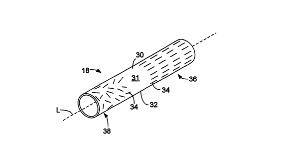
FIG 1 is a cross-sectional side view of an embodiment of a balloon catheter.
FIG 2 is a perspective view of an embodiment of a tube for a balloon catheter
system.
FIG 3A is an illustration of an embodiment of an apparatus for making a tube
for a
balloon catheter system.
FIG 3B is a side view of a portion of the apparatus of FIG 3A.
FIG 3C is a perspective view of a portion of the apparatus of FIG 3A, when
exposed
to a magnetic field.
FIG 3D is a perspective view of a portion of the apparatus of FIG 3A, when
extruding a material under exposure to a magnetic field.
FIG 3E is a perspective view of a portion of the apparatus of FIG 3A, when
exti-uding a material under exposure to a magnetic field.
FIG 3F is a perspective view of an embodiment of a tube for a balloon catheter
system.
-5-
CA 02577783 2007-02-20
WO 2006/029136 PCT/US2005/031667
FIG 3G is a perspective view of a portion of the apparatus of FIG 3A, when
extruding a material that is not under exposure to a magnetic field.
FIG 3H is a perspective view of an embodiment of a tubular member.
FIG 4A is a perspective view of an embodiment of a tube for a balloon catheter
system.
FIG 4B is a cross-sectional side view of the tube of FIG 4A, taken along line
4B-4B.
FIG 5A is a perspective view of an embodiment of a tube for a balloon catheter
system.
FIG 5B is an exploded view of the tube of FIG 5A.
FIG 6 is a cross-sectional side view of an embodiment of a tube for a balloon
catheter
system.
FIG 7 is an illustration of an embodiment of an apparatus for making a tube
for a
balloon catheter system.
FIG 8A is a cross-sectional side view of an embodiment of a balloon.
FIG 8B is a cross-sectional side view of an embodiment of a balloon.
FIG 9 is a perspective view of an embodiment of a tube for a balloon catheter
system.
FIG 10A is a side view of an einbodiment of an apparatus for making a tube for
a
balloon catheter system.
FIG l OB is a front view of the apparatus of FIG 10A.
DETAILED DESCRIPTION
Referring to FIG. 1, a balloon catheter system 10 includes a catheter 12 and
an
inflatable balloon 14 carried by the catheter. Catheter 12 includes an outer
shaft 16 and an
inner shaft 18 defining a lumen 19. Shafts 16 and 18 are concentric and define
an annular
lumen 20 between them. During use, catheter system 10 can be delivered to a
treatment area
(e.g., a coronary artery) by passing lumen 19 over a guide wire 22 emplaced in
the body, and
pushing the catheter system to the treatment area. Balloon 14 can then be
inflated or deflated
by delivering or withdrawing a fluid (such as a liquid or a gas) through
annular lumen 20.
Examples of balloon catheter systems are described in U.S. Patent Nos.
5,195,969 and
5,270,086.
-6-
CA 02577783 2007-02-20
WO 2006/029136 PCT/US2005/031667
Referring now to FIG. 2, inner shaft 18 is tubular and is formed of a
continuously
extruded polymer composite layer 30 that includes a polymer matrix 32 and
magnetically
alignable fibers 34 embedded in the polymer matrix. Inner shaft 18 has a
relatively stiff
proximal end 36 and a relatively flexible distal end 38. The magnetically
alignable fibers in
proximal end 36 are oriented parallel to the longitudinal axis "L" of inner
shaft 18,
contributing to the relative stiffness of proximal end 36. The magnetically
alignable fibers in
proximal end 36 have a non-random orientation because they have all been
oriented
substantially in the same direction. The magnetically alignable fibers in
distal end 38 are
randomly oriented, contributing to the relative flexibility of distal end 38.
The stiffness of
proximal end 36 provides imzer shaft 18 witli good pushability, while the
flexibility of distal
end 38 provides inner shaft 18 with good trackability. As shown in FIG. 2, the
intermediate
region 37 of imier shaft 18 does not include any magnetically alignable fibers
34. However,
in some embodiments (and as shown below), intermediate region 37 can include
magnetically alignable fibers 34.
Referring to FIG. 3A, inner shaft 18 can be made, for example, using a tube-
forming
apparatus 90. Tube-forming apparatus 90 includes an extrusion head 92, a
quench tank 94, a
laser micrometer 96, a puller 98, and a cut-off knife 100. Extrusion head 92
includes a
housing 102 that encloses three sections of the extrusion head: a magnetic
field-generating
section 110, a polyiner feed section 120, and an extrusion die 126. Magnetic
field-generating
section 110 includes a steel sleeve 112, an iron tip guide 114, and a coil 116
(e.g., a solenoid)
disposed between iron tip guide 114 and steel sleeve 112. Polymer feed section
120 includes
a polymer feed 122 that, via a polymer feed shaft 123, is in fluid
communication with a
hollow tip 124 that extends through all three sections of extrusion head 92.
To forin inner shaft 18, a polymer composite that includes a polymer matrix
material
and magnetically alignable fibers 34 is added into polymer feed 122. While it
is in polyiner
feed 122, the polymer composite is melted to form a liquid polyiner composite
stream (e.g., a
magnetorheological fluid) that flows through polymer feed shaft 123, and into
tip 124,
exiting extrusion head 92 through extrusion die 126. The polymer composite
stream starts to
solidify upon exiting extrusion head 92 through extrusion die 126, at which
point the
polymer composite stream is exposed to the ambient environment. As the polymer
composite stream solidifies, it forins a tubular member 130. As the polymer
composite is
-7-
CA 02577783 2007-02-20
WO 2006/029136 PCT/US2005/031667
being extruded, pressurized air (shown in FIG. 3A as a solid black line) flows
through the
center of hollow tip 124. The pressurized air causes the polymer composite
streain to form a
tubular shape as it is extruded. As an alternative to pressurized air, in some
embodiments,
the polymer composite stream can be extruded over a mandrel (not shown) that
causes the
polymer coinposite stream to form a tubular shape when it is extruded. The
mandrel can be
fonned of, for example, cast iron, carbon steel, or stainless steel (e.g., 306
stainless steel, 316
stainless steel, 440C stainless steel). After exiting extrusion die 126,
tubular meinber 130
passes through quench tank 94, for further cooling and solidification.
Thereafter, tubular
member 130 passes through laser micrometer 96, where it is sized, and through
puller 98,
which pulls tubular member 130 from extrusion die 126, through quench tank 94
and laser
micrometer 96, and directs tubular member 130 toward cut-off knife 100.
Referring now to FIG. 3B, the orifice of extrusion die 126 has a diameter po,
hollow
tip 124 has an outer diameter ODH, and tubular member 130 has an inner
diameter IDT and
an outer diameter ODT. Operation of the puller 98 affects the draw-down ratio
[(Do)/(ODT)]
and the draw-balance ratio [((Do)/(ODT))/((ODH)/(IDT))] of tubular member 130.
In
einbodiments, the draw-down ratio of tubular member 130 can be from about two
to about
2.5. Alternatively or additionally, the draw-balance ratio of tubular member
130 can be from
about 1.05 to about 1.1. Finally, tubular member 130 passes through cut-off
knife 100,
which cuts tubular member 130 into smaller pieces, such as inner shaft 18.
Inner shaft 18
can then be incorporated into catheter system 10 by conventional methods. For
example,
inner shaft 18 can be attached to balloon 14 using an adhesive, laser welding,
and/or RF
welding.
Suitable operating conditions for tube-forming apparatus 90, such as zone
heating
temperatures, polymer concentrations, feed rate, and line speed, are
described, for example,
in Chin et al., U.S. Published Patent Application No. 2002/0165523 Al, which
is
incorporated herein by reference in its entirety.
During the extrusion process, a magnetic field is applied to the polyiner
composite
stream to align the magnetically alignable material within the polymer
coinposite stream.
Referring to FIG. 3A, coi1116 is selectively activated (by passing electrical
current through
the coil) to align magnetically alignable fibers 34 within the polymer
composite stream. As
shown in FIG. 3 C, when coil 116 is activated, it generates a magnetic field
force in the
-8-
CA 02577783 2007-02-20
WO 2006/029136 PCT/US2005/031667
direction of arrows F. Iron tip guide 114 propagates the magnetic field along
the length of tip
124, from the location of coil 116 to extrusion die 126. Thus, the polyiner
composite stream
is exposed to the magnetic field as the polymer composite stream flows through
tip 124 and
extrusion die 126. Exposure of the liquid polymer composite stream to the
magnetic field
can cause magnetically alignable fibers 34 to respond by aligning themselves
with the field.
As shown in FIG. 3D, when coil 116 is activated during the formation of
tubular member
130, the resultant magnetic field causes magnetically alignable fibers 34 to
become aligned
parallel to the longitudinal axis "Ll" of tubular member 130.
In some embodiments, and referring now to FIG. 3E, the resultant magnetic
field can
cause magnetically alignable fibers 34 to line up in a "train" formation. The
train fonnation
can occur as a result of a magnetic dipole being formed along the axis of each
fiber 34. This
magnetic dipole causes the fibers to join end-to-end (e.g., in close
proximity, contacting),
thereby forming a long, fibrous train of fibers 34. In certain embodiments, a
train formation
can be created using spherical magnetically alignable particles. For example,
FIG. 3F shows
a shaft 900 with a proximal end 902, a distal end 904, and a longitudinal axis
"L2". Shaft
900 is tubular and is formed of a continuously extruded polymer coinposite
layer 906 that
includes a polymer matrix 908 and spherical magnetically alignable particles
910 embedded
in the polymer matrix. While the magnetically alignable particles at distal
end 904 are
randoinly dispersed throughout polymer matrix 908, the magnetically alignable
particles at
proximal end 902 have aligned so that they form long trains 912 of the
particles. Trains 912,
which are oriented parallel to longitudinal axis "L2" of shaft 900, cause
proximal end 902 of
shaft 900 to be relatively stiff. By contrast, distal end 904, with its
randomly oriented
particles, is relatively flexible. The formation of trains of magnetic
particles is described, for
example, in Cutillas & Liu, "Dynamics of Single Chains of Suspended Ferrofluid
Particles,"
presented at the Fourtli Microgravity Fluid Physics & Transport Phenomena
Conference
(Aug. 12-14, 1998, Cleveland, Ohio), pages 100-105, which is incorporated
herein by
reference.
FIG. 3G shows that the deactivation of coil 116 results in magnetically
alignable
fibers 34 having a random orientation, since they are no longer exposed to a
magnetic field.
In some embodiments, activation or deactivation of coil 116 can affect the
concentration of
magnetically alignable fibers 34. For example, the magnetic field created by
coil 116 can
-9-
CA 02577783 2007-02-20
WO 2006/029136 PCT/US2005/031667
pull magnetically alignable fibers 34 through the liquid polymer composite as
it is being
extruded. When coil 116 is deactivated, this pulling force stops, such that
magnetically
alignable fibers 34 remain where they are in the polymer composite. Thus, a
section of the
extruded tube that was formed while coil 116 was activated may have a higher
concentration
of magnetically alignable fibers 34 than a section of the extruded tube that
was formed while
coil 116 was deactivated. A medical device component such as imler shaft 18
can be formed
by activating coil 116 during one part of the extrusion process (e.g., during
the formation of
relatively stiff proximal end 36), and deactivating coil 116 during another
part of the
extrusion process (e.g., during the formation of relatively flexible distal
end 38).
In some embodiments, and referring now to FIG. 3H, tubular member 130 can be
formed to have a relatively stiff proximal end 36, a relatively flexible
distal end 38, and an
intermediate region 37 with a flexibility between that of proximal end 36 and
distal end 38.
As shown, interinediate region 37 includes magnetically alignable fibers 34
that all have the
same orientation relative to longitudinal axis "L3" of tubular member 130, but
that are not
aligned parallel to longitudinal axis "L3". Intermediate region 37 of tubular
member 130 can
be fonned, for example, as coil 116 is deactivated. Prior to deactivation of
coil 116, the
magnetically alignable fibers 34 in intermediate region 37 begin to become
aligned relative
to longitudinal axis "L3". However, coil 116 is deactivated before the
magnetically alignable
fibers in the intermediate region can be aligned parallel to longitudinal axis
"L3". Thus, the
magnetically alignable fibers in the intermediate region are "partially
aligned" relative to
longitudinal axis "L3". Because intermediate region 37 includes magnetically
alignable
fibers with an intermediate alignment relative to the fibers in proximal end
36 and distal end
38, intermediate region 37 has an intermediate flexibility, as well.
The strength of the magnetic field (e.g., created by a coil such as coil 116)
that is
applied to magnetically alignable material can be selected based on the extent
of alignment
desired for the magnetically alignable material. In some instances, the
strength of the
magnetic field that is selected to induce a certain extent of aligrunent of
the magnetically
alignable material may depend on the type of polymer in which the magnetically
alignable
material is embedded, and/or on the size of the magnetically alignable
material. For
example, a magnetic field with a relatively high magnetic field strength may
be used to align
magnetically alignable material (e.g., fibers, particles) that is relatively
small in size, and/or
-10-
CA 02577783 2007-02-20
WO 2006/029136 PCT/US2005/031667
that is embedded in a polymer with a relatively high polymer melt viscosity.
Another factor
that may influence the strength of the magnetic field selected to align the
magnetically
alignable material is the magnetic permeability of the magnetically alignable
material. As an
example, in some embodiments, a magnetic field with a relatively high magnetic
field
strength can be used to align iron particles that have a diameter of about one
micron and that
are suspended in a molten 72 durometer Pebax matrix. As another example, in
certain
embodiments, a magnetic field with a relatively low magnetic field strength
can be used to
align iron particles that have a diameter of about ten microns and that are
suspended in a low
density polyethylene matrix. In some embodiments, the magnetic field (e.g.,
created by a
coil such as coi1116) that is applied to magnetically alignable material can
have a magnetic
field strength of from about 25 gauss to about 600 gauss (e.g., from about 100
gauss to about
400 gauss).
While the above-described processes have been described with respect to inner
shaft
18, in some embodiments, other components of balloon catheter system 10 can
alternatively
or additionally be formed as described above with respect to inner shaft 18.
For example,
outer shaft 16 can include magnetically alignable material having different
orientations along
the length of outer shaft 16.
Examples of magnetically alignable materials include ferromagnetic materials.
A
ferromagnetic material has a magnetic susceptibility of at least about 0.075
when measured at
25 C, and can be, for example, a metal (e.g., a transition metal such as
nickel, cobalt, or
iron), a metal alloy (e.g., a nickel-iron alloy such as Mu-metal), a metal
oxide (e.g., an iron
oxide such as magnetite), a ceramic nanomaterial, a soft ferrite (e.g., nickel-
zinc-iron), a
magnet alloy (e.g., a rare earth magnet alloy such as a neodymium-iron-boron
alloy or a
samarium-cobalt alloy), an amorphous alloy (e.g., iron-silicon-boron), a non-
earth alloy, or a
silicon alloy (e.g., an iron-zirconiuin-copper-boron-silicon alloy, an iron-
zirconium-copper-
boron-silicon alloy). Magnetite is commercially available from FerroTec
Corporation
(Nashua, NH), under the trade name EMG 1111 Ferrofluid. Iron-copper-niobium-
boron-
silicon alloys are commercially available from Hitachi Metals of America under
the trade
name FinemetTM. Iron-zirconium-copper-boron-silicon alloys are commercially
available
from MAGNETEC GmbH under the trade name Nanoperm .
-11-
CA 02577783 2007-02-20
WO 2006/029136 PCT/US2005/031667
In certain embodiments, magnetically alignable fibers 34 can have an average
length
of from about 50 nanometers to about 25 microns (e.g., from about 0.5 inicron
to about ten
microns). Alternatively or additionally, magnetically alignable fibers 34 can
have an average
width and/or diameter of from about 50 nanometers to about 25 microns (e.g.,
from about 0.5
micron to about ten microns). In some embodiments, the magnetically alignable
material in a
polymer composite can be a nanomaterial. Nanomaterials include particles
and/or fibers
having at least one dimension less than about 1000 nm.
In certain embodiments, magnetically alignable fibers can have an average
aspect
ratio of from about 1:1 to about 10:1 (e.g., from about 1:1 to about 5:1).
While magnetically alignable fibers have been shown, other forms of
magnetically
alignable material can be used in a polymer composite. For example, the
magnetically
alignable material can be in the forin of particles, flakes, and/or a powder.
In some embodiments, the concentration of magnetically alignable fibers in the
polymer composite stream can be from about two weight percent to about 50
weight percent
(e.g., from about five weight percent to about ten weight percent).
Exemplary polymer matrix materials for a polymer composite material include
thermoplastics and thermosets. Examples of thermoplastics include, for
example,
polyolefins; polyamides, such as nylon 12, nylon 11, nylon 6/12, nylon 6, and
nylon 66;
polyesters; polyethers; polyurethanes; polyureas; polyvinyls; polyacrylics;
fluoropolymers;
copolymers and block copolymers thereof, such as block copolymers of polyether
and
polyamide, e.g., Pebax (e.g., PebaxO with a relatively high durometer value,
such as 50);
and mixtures thereof. Examples of thermosets include elastomers such as EPDM,
epichlorohydrin, nitrile butadiene elastomers, silicones, etc. Conventional
thermosets such as
epoxies, isocyanates, etc., can also be used. Biocompatible thermosets, for
example,
biodegradable polycaprolactone, poly(dimethylsiloxane) containing
polyurethanes and ureas,
and polysiloxanes, may also be used. One or more of these materials can be
used in the
polymer composite material, in any combination.
Other polymer matrix materials include, for example, elastomers such as
thermoplastic elastomers and engineering thermoplastic elastomers, such as
polybutylene
terephthalate-polyethene glycol block copolymers, which are available, for
example, as
HYTREL . Elastomers are discussed, for example, in Hamilton U.S. Patent No.
5,797,877,
-12-
CA 02577783 2007-02-20
WO 2006/029136 PCT/US2005/031667
which is incorporated herein by reference in its entirety. Other polymers
include liquid
crystal polymers (LCP's). Examples of LCPs include polyester(s), polyamide(s)
and/or their
copolymers, such as VECTRA A (Ticona), VECTRA B (Ticona) and VECTRA LKX
(Ticona) (e.g., VECTRA LKX 1111 (Ticona)).
While a tubular member including a single polymer composite has been
described, in
some embodiments, a medical device can include at least one polymer composite
and at least
one polymer (e.g., a polymer that is substantially fiee of magnetically
alignable material), or
at least two different polymer composites.
As an exainple, FIGS. 4A and 4B show a tubular member 300 that includes one
section 310 formed of a polymer 312, and another section 320 formed of a
polymer
composite 324. Polymer composite 324 includes a polymer matrix 326 and
magnetically
alignable fibers 328. In region 332 of section 320, magnetically alignable
fibers 328 have a
random orientation, while in region 334 of section 320, magnetically alignable
fibers 328 are
aligned parallel to the longitudinal axis "L4" of tubular member 300. Polymer
matrix 326
can be the same polymer as polymer 312, or can be different from polymer 312.
Because of
the presence of magnetically alignable fibers 328 in section 320, and the
absence of
magnetically alignable fibers 328 in section 310, section 320 has a higher
magnetic
permeability than section 310. In some embodiments, section 310 can have a
magnetic
permeability of from about one to about 20 (e.g., from about one to about
seven).
Alternatively or additionally, section 320 can have a magnetic permeability of
from about
five to about 30.
As another exainple, in some einbodiments, a tubular member can include more
than
one layer of material. For example, FIGS. 5A and 5B show a tubular member 400
that
includes an inner layer 410 and an outer layer 420. Inner layer 410 includes a
polymer 412,
while outer layer 420 is formed of a polymer composite 422 that includes a
polyiner matrix
424 and magnetically alignable fibers 426. In region 430 of tubular member
400,
magnetically alignable fibers 426 are randomly oriented, while in region 440
of tubular
meinber 400, magnetically alignable fibers 426 are aligned parallel to the
longitudinal axis
"L5" of tubular member 400. In some embodiments, polymer matrix 424 of outer
layer 420
can include a stiff polymer, so that the catheter system of which tubular
member 400 is a part
can be advanced through the body easily (e.g., without kinking or buckling).
Alternatively or
-13-
CA 02577783 2007-02-20
WO 2006/029136 PCT/US2005/031667
additionally, polymer 412 of inner layer 410 can be a polymer that gives inner
layer 410 a
smooth and lubricious inner surface (e.g., high density polyethylene), to, for
example, ease
passage of a guide wire through tubular member 400. While inner layer 410 is
shown
including polymer 412 and outer layer 420 is shown including polymer composite
422, a
multilayer tubular member can include other arrangements of materials. As an
example, a
multilayer tubular member can have an inner layer that includes a polylner
composite and an
outer layer that includes a polymer. As another example, all of the layers of
a multilayer
tubular member can include a polymer composite. As a further example, a
multilayer tubular
member can have inner and outer layers that include a polymer composite, and
an
intermediate layer that includes a polyrner.
In some einbodiments, the layers of material in a tubular member can have
varying
thicknesses. For example, FIG. 6 shows a cross-sectional view of a tubular
member 500 that
includes an inner layer 510 and an outer layer 520. Layers 510 and 520 have
varying
thicknesses along the length of tubular member 500. As shown, inner layer 510
includes a
polymer composite 512 that includes a polymer 514 and magnetically alignable
material 516,
and outer layer 520 includes a polymer 522; in other embodiments, the
locations of polymer
composite 512 and polyiner 522 can be reversed.
Tubular members (such as those shown in FIGS. 4A, 4B, 5A, 513, and 6) that
include
two polymer composites or a polyiner and a polymer composite can be formed,
for example,
using the tube-fonning apparatus 200 shown in FIG. 7. Tube-forming apparatus
200
includes an extrusion head 202, a quench tank 204, a laser micrometer 206, a
puller 208, and
a cut-off knife 210. Extrusion head 202 has a housing 212 that encloses three
sections of the
extrusion head: a magnetic field-generating section 220 that includes a steel
sleeve 222, an
iron tip guide 224, and a coi1226 (e.g., a solenoid) between iron tip guide
224 and steel
sleeve 222, a polymer feed section 230 that includes a first polymer feed 232,
and an
extrusion die 236. Hollow tip 234 passes through all three sections of
extrusion head 202,
and is in fluid communication with first polymer feed 232.
Polymer feed section 230 of apparatus 200 furtller includes a second polymer
feed
242 that, lilce first polymer feed 232, is in fluid cormnunication with tip
234. To form a
tubular polymer member, a polymer is added into first polymer feed 232, and a
polymer
composite is added into second polymer feed 242. The polymer and polymer
composite are
-14-
CA 02577783 2007-02-20
WO 2006/029136 PCT/US2005/031667
melted to form liquid polymer and polymer composite streams that enter tip
234. The
streams are then extruded through extrusion die 236, solidifying upon exposure
to the
ambient environment and thereby fonning a tubular member 250. During the
formation of
tubular member 250, pressurized air (shown in FIG. 7 as a solid black line)
flows through the
center of hollow tip 234, causing the polymer and polymer composite streams to
form a
tubular shape (i.e., tubular member 250). In some embodiments, the polymer and
polyiner
composite streams can be extruded using an intermittent extrusion process,
such as the
process described in Wang, U.S. Patent No. 5,533,985, which is incorporated
herein by
reference in its entirety. In certain embodiments, the polymer and polymer
composite
streains can be extruded using a gradient extrusion process, such as the
process described in
Harris, U.S. Patent No. 5,695,789, which is incorporated herein by reference
in its entirety.
Other methods are described, for example, in U.S. Patent Application Serial
No. 10/645,014,
filed August 21, 2003, and entitled "Multilayer Medical Devices"; WO 01/32398;
and Burlis
et al., U.S. Patent No. 3,752,617.
The polymer composite stream that flows through extrusion apparatus 212
includes
magnetically alignable material. During extrusion and formation of tubular
member 250, the
polymer coinposite stream can be exposed to a magnetic field that aligns the
magnetically
alignable material within the polymer composite stream. The magnetic field can
be
generated by activating coi1226 (by passing electrical current through the
coil). Iron tip
guide 224 propagates the magnetic field such that it is present along the
length of hollow tip
234. Thus, the magnetic field affects the polymer composite stream as it flows
through tip
234 and out through extrusion die 236.
Because tube-forming apparatus 200 includes two polymer feeds (232 and 242),
tubular member 250 includes a section that is formed of a polymer and a
section that is
formed of a polymer composite. Each section can be in the form of a portion of
tubular
member 250 or a layer of tubular member 250.
Tubular member 300 of FIGS. 4A and 4B can be formed by deactivating coil 226
both during formation of section 310 and during formation of region 330 of
section 320. The
deactivation of coil 226 causes the magnetically alignable fibers in region
330 to be
randomly oriented. However, coil 226 is activated when region 332 of section
320 is formed,
-15-
CA 02577783 2007-02-20
WO 2006/029136 PCT/US2005/031667
such that the magnetically alignable fibers in region 320 are aligned parallel
to the
longitudinal axis "L2" of tubular member 300.
Tubular member 400 of FIGS. 5A and 5B can be formed by coextruding layers 410
and 420, deactivating coil 226 during the formation of section 430, and
activating coi1226
during the formation of section 440. Similarly, tubular member 500 of FIG. 6
can be formed
by coextruding layers 510 and 520, and activating or deactivating coi1226
according to the
desired level of alignment of magnetically alignable materia1516 in layer 510.
Materials other than polymers can be incorporated into an extr-usion process
during
the formation of a multilayer tubular member. For example, an adhesion
enhancing material
can be incorporated into one or more material layers. An adhesion enhancing
material can be
used, for example, to enhance the adhesion between adjacent layers. Examples
of adhesion
enhancing materials include epoxy or anhydride modified polyolefins, such as
LOTADER
(Atofina SA), KODAR PETG (Eastman Kodak), and Plexar (Equistar Chemicals
LP).
For example, in embodiments in which one layer includes high-density
polyethylene and
another layer includes Pebax , a Plexar layer can be included between the two
layers to
enhance adhesion. In some einbodiments, an adhesion enhancing material can be
added to a
material (e.g., a composition containing one or more polymers) prior to
extrusion. For
example, in embodiments in which alternate layers are formed of PET and PBT,
PETG can
be added to the PET before extrusion.
In some embodiments, a compatibilizing material can be incorporated into one
or
more material layers. In certain embodiments, the compatibilizing material can
enhance the
compatibility between the layer(s) and one or more other layers in a
multilayer medical
device or medical device component. Examples of such coinpatibilizing
materials include
copolyester elastomers, ethylene unsaturated ester copolymers, such as
ethylene-maleic
anhydride copolyrners, copolymers of ethylene and a carboxylic acid or acid
derivative, such
as ethylene-methyl acrylate copolymers, polyolefins or ethylene-unsaturated
ester
copolymers grafted witli functional monomers, such as ethylene-methyl acrylate
copolymers,
copolymers of ethylene and a carboxylic acid or acid derivative, such as
ethylene-methyl
acrylate maleic anhydride terpolyiners, terpolylners of ethylene, unsaturated
ester and a
carboxylic acid or acid derivative, such as ethylene-methyl acrylate-
inethacrylic acid
terpolymers, maleic acid grafted styrene-ethylene-butadiene-styrene block
copolymers, and
-16-
CA 02577783 2007-02-20
WO 2006/029136 PCT/US2005/031667
acrylic acid elastomers, such as acrylic rubbers. Similar polymers containing
epoxy
functional groups, for instance derived from glycidyl methylacrylate (e.g.,
allcyl(ineth)acrylate-ethylene-glycidyl (meth)acrylate polymers) can be used.
lonomeric
copolyiners can be used. PETG can be used. Examples of compatibilizing
materials include
HYTREL HTR-6108, POLYBOND 3009 (BP Chemicals), SP 2205 (Chevron), DS
1328/60 (Chevron), LOTADER 2400, ESCOR ATX-320, ESCOR ATX-325,
VAMAC G1 and LOTADER AX8660. In certain embodiments, a compatibilizing
material (e.g., PETG) can be mixed with one or more polymers (e.g., an LCP-
containing
material) prior to extrusion.
In some embodiments, a compatibilizing material can be used to enhance the
compatibility between the magnetically alignable material (e.g., inagnetically
alignable
fibers) and one or more polymers in a medical device or medical device
component.
Examples of such coinpatibilizing materials include both organic and inorganic
materials.
Suitable organic compatibilizing materials can be both low molecular weight
molecules and
polymers. Exainples of low molecular weight organic compatibilizing materials
include, but
are not limited to, amino acids (e.g., 12-aminododecanoic acid) and thiols.
Examples of
polymeric compatibilizers include functionalized polymers, such as maleic
anhydride
containing polyolefins or maleimide-functionalized polyamides. Inorganic
compatibilizing
materials can include, for example, alkoxides of silicon, aluminum, titanium,
and zirconium.
Compatibilizing materials are fiirther described, for example, in U.S.
Published Patent
Application No. 2003/0093107 Al, published on May 15, 2003, which is
incorporated herein
by reference.
Other Embodiments
While certain embodiments have been described, the invention is not so
limited.
In some embodiments, the tubes and/or methods described herein can be used to
form
other medical devices or medical device components. Examples of medical
devices include
catheters (e.g., balloon catheters), balloons, guide wires, endoprosthesis
delivery systems
(e.g., stent delivery systems). Balloons are described, for example, in U.S.
Published Patent
Application No. 2004/0078052 Al, published Apri122, 2004, which is
incorporated herein
by reference. Guide wires are described, for example, in Wang et al., U.S.
Patent No.
-17-
CA 02577783 2007-02-20
WO 2006/029136 PCT/US2005/031667
6,436,056, which is incorporated herein by reference. Stent delivery systems
are described,
for example, in Raeder-Devens et al., U.S. Patent No. 6,726,712, which is
incorporated
herein by reference. In some embodiments, the tubes and/or methods described
herein can be
used to form a dual lumen catheter with a shaft that includes multiple shaft
sections and
longitudinally extending lumens that are positioned side by side. Such
catheters are
described, for example, in Maguire et al., U.S. Patent No. 4,782,834, which is
incorporated
herein by reference. In some embodiments, the above-described tubes and/or
methods can be
used in Intermittent Layer Coextrusion (ILC), which is described, for example,
in Wang,
U.S. Patent No. 5,622,665; U.S.S.N. 10/645,014, filed on August 21, 2004, and
entitled
"Multilayer Medical Devices"; U.S.S.N. 10/645,055, filed on August 21, 2003,
and entitled
"Medical Balloons"; and U.S.S.N. 10/787,777, filed on February 26, 2004, and
entitled
"Balloon Catheter", all of which are incorporated herein by reference in their
entirety. In
certain embodiments, the tubes described herein can have an enhanced ability
to conduct
low-voltage electricity and can be used, for example, in endoscopic
applications.
For example, and referring now to FIG. 8A, a tube formed by one of the above-
described processes can be used to manufacture a medical balloon 600. Medical
balloon 600
is formed of a polyiner composite 610 that includes a polymer 612 and
magnetically
alignable fibers 614. As shown, fibers 614 are aligned at each of the waist
sections 620 and
630 of balloon 600, and are randomly oriented at the expandable section 640 of
balloon 600.
However, in other embodiments, one or both of the waist sections of a balloon
can include
randomly oriented fibers, and/or the expandable section of a balloon can
include aligned
fibers. Also, while regions 675 of balloon 600 are shown as not including
magnetically
alignable material, in some embodiments, regions 675 can include magnetically
alignable
material (e.g., magnetically alignable fibers) that is aligned or randomly
oriented, or that has
an alignment that is between the alignment of fibers 614 at waist sections 620
and 630, and
the random orientation of fibers 614 at expandable section 640.
Balloon 600 can be formed, for example, by a blow molding process in which a
tube
is placed (e.g., centered) in a preheated balloon mold, and air is introduced
into the tube to
maintain the patency of the tube lumen. In some embodiments, after being
soaked at a
predetermined temperature and time, the tube can be stretched for a
predetermined distance
at a predetermined time, rate, and temperature. The pressure inside the tube
can then be
-18-
CA 02577783 2007-02-20
WO 2006/029136 PCT/US2005/031667
sufficiently increased to radially expand the tube inside the mold to form the
balloon. The
formed balloon can be heat treated, for example, to enhance folding memory,
and/or folded
into a predetermined profile. The balloon can then be attached to a catheter
to form a balloon
catheter. Illustrative methods of forming a balloon from a tube are described
in, for example,
commonly-assigned U.S. Patent Application Serial No. 10/263,225, filed October
2, 2002,
and entitled "Medical Balloon"; Anderson, U.S. Patent No. 6,120,364; Wang,
U.S. Patent
No. 5,714,110; and Noddin, U.S. Patent No. 4,963,313, all of which are
incorporated herein
by reference in their entirety.
Referring now to FIG. 8B, in some embodiments, the molding of a balloon 650
can
form relatively thick-walled waist regions 660, which can reduce the
flexibility and
trackability of the balloon. For example, during molding, the body portion 670
of the balloon
can be stretched diametrically by at least a factor of six. As a result, the
balloon wall in body
portion 670 can be relatively thin because of the relatively large amount of
stretching.
However, portions of the balloon other than body portion 670, such as waist
regions 660,
may stretch relatively little (e.g., by a factor of approximately two). As a
result, the portions
of balloon 650 other than body portion 670 can remain relatively thick and can
be inflexible.
However, the addition of randomly oriented magnetically alignable fibers 680
to waist
regions 660 can enhance the flexibility of the waist regions, while the
addition of aligned
magnetically alignable fibers 690 to body portion 670 can enhance the
stiffness of body
portion 670.
While not shown, in some embodiments, a balloon that includes magnetically
alignable material can also include one or more cutting elements. Suitable
materials for the
cutting elements include, for example, stainless steel and plastic. Balloons
with cutting
elements are described, for exainple, in U.S. Published Patent Application No.
2003/0163148
Al, published on August 28, 2003; U.S. Published Patent Application No.
2004/0133223 Al,
published on July 8, 2004; and U.S.S.N. 10/744,507, filed on December 22,
2003, and
entitled "Medical Device Systems", all of which are incorporated herein by
reference.
As mentioned above, a tube formed according to one of the above-described
processes can be formed into a guide wire, e.g., a polymer guide wire. Methods
of making a
guide wire, including one having good pushability, are described, for example,
in U.S. Patent
No. 5,951,494, which is incorporated herein by reference in its entirety.
-19-
CA 02577783 2007-02-20
WO 2006/029136 PCT/US2005/031667
In certain embodiments, a tubular member can include magnetically alignable
material that is aligned laterally relative to the longitudinal axis of the
tubular member. For
example, FIG. 9 shows a tubular member 700 formed of a polymer composite 702
that
includes a polymer 704 and magnetically alignable fibers 706. Magnetically
alignable fibers
706 are aligned laterally relative to the longitudinal axis "L6" of tubular
member 700.
Tubular member 700 can be formed, for example, using the tube-forming
apparatus
800 shown in FIGS. 10A and l OB. Tube-forming apparatus 800 includes an
extrusion head
810 with a housing 812 enclosing two sections: a polymer feed section 820
including a
polymer feed 822, and an extrusion die 830. A hollow tip 840 extends through
polymer feed
section 820 and extrusion die 830, and is in fluid communication with polymer
feed 822.
Tubular member 700 can be formed similarly to the processes described above
with
reference to apparatus 90 of FIG. 3A and apparatus 200 of FIG. 7. However,
tube-forming
apparatus 800 generates a different type of magnetic field from the above-
described
apparatuses. As shown in FIGS. 10A and l OB, tube-forming apparatus 800
includes a
magnet 850, in the bottom 852 of which is embedded a solenoid 860. When
solenoid 860 is
activated (by passing an electrical current through the solenoid), it
generates a magnetic field
that is propagated by magnet 850 to form a magnetic field force indicated by
arrows Fl.
Thus, as the polymer composite stream exits extrusion die 830, it is exposed
to a magnetic
field that causes magnetically alignable fibers 706 to align laterally
relative to tubular
component 700.
In some embodiments, a medical device or medical device component can be
formed
by extruding a polymer composite through an extrusion head that includes a
hollow tip and a
magnetic mandrel disposed within the hollow tip. The magnetic mandrel can
generate a
magnetic field that aligns the magnetically alignable material within the
polymer composite.
In certain einbodiments, a tubular member can be formed by extruding a polymer
composite while applying a varying magnetic field to the polymer composite.
For example, a
coil (e.g., a solenoid) can be activated (by passing an electrical current
through the coil) to
form a magnetic field. The magnetic field can be applied to the polymer
composite as the
polymer composite is being extruded. The magnetic field can be selectively
reduced,
increased, and/or deactivated as the polymer composite is being extruded, to
vary the degree
of alignment of the magnetically alignable material in the polymer composite.
-20-
CA 02577783 2007-02-20
WO 2006/029136 PCT/US2005/031667
In some embodiments, as a tubular member is extruded, the tubular member can
be
rotated relative to the longitudinal axis of the tubular member. The rotation
of the tubular
member as it is being extruded can, for example, further enhance the
rotational or torsional
stiffness of the tubular member. Extruded tubing formed by rotation during an
extrusion
process is described, for example, in Zdrahala, U.S. Patent No. 5,238,305, and
in U.S.S.N.
10/83 8,540, filed on May 4, 2004, and entitled "Medical Devices", both of
which are
incorporated herein by reference.
In certain embodiments, a tubular component can be made with aligned
magnetically
alignable materials, and can later be connected (e.g., by welding) to a
tubular component that
does or does not include aligned magnetically alignable material, to form a
tubular member.
In some embodiments, a magnetic field can be applied to a polymer composite
that
includes a resin such as a thixotropic resin and, for example, nanotubes
(e.g., carbon
nanotubes, ceramic nanotubes). Without wishing to be bound by theory, it is
believed that
the magnetic field can cause the polymers of the thixotropic resin to orient
tliemselves
relative to the field, and to thereby indirectly orient the nanotubes by
pulling the nanotubes
along with them. In such embodiments, the magnetic field strength of the
magnetic field that
is applied to the polymer composite can be at least about ten Tesla (e.g., at
least about 15
Tesla, at least about 20 Tesla) and/or at most about 25 Tesla (e.g., at most
about 20 Tesla, at
most about 15 Tesla). The orientation of carbon nanotubes in a polymer
composite is
described, for example, in Choi et al., "Enhancement of Thennal and Electrical
Properties of
Carbon Nanotube Polymer Composites by Magnetic Field Processing," 94 Journal
of
Applied Physics 9 (Nov. 1, 2003), 6034-6039, which is incorporated herein by
reference in its
entirety. Extrusion of nanocomposites is described, for exainple, in U.S.S.N.
10/728,079,
filed on December 4, 2003, and entitled "Medical Devices", which is
incorporated herein by
reference.
In certain einbodiments, a polymer can be oriented by applying a magnetic
field to
magnetically alignable material (e.g., magnetically alignable fibers and/or
particles)
dispersed within the polymer. For example, a polymer composite that includes
magnetically
alignable fibers can be extruded to form a tubular member. As the middle
portion of the
tubular member is being formed, a magnetic field can be applied to the polymer
composite to
orient the magnetically alignable fibers in the middle portion with respect to
the longitudinal
-21-
CA 02577783 2007-02-20
WO 2006/029136 PCT/US2005/031667
axis of the tubular member. The orientation of the magnetically alignable
fibers can cause
the surrounding polymer to become oriented, as well. As the end portions of
the tubular
member are extruded, the magnetic field can be deactivated, such that the
magnetically
alignable fibers in the end portions do not become oriented with respect to
the longitudinal
axis of the tubular member, and thus do not orient the surrounding polyiner.
After the tube
has been extruded, it can be formed into a balloon (e.g., as described above)
having a
relatively stiff body region (formed out of the middle portion of the tubular
member), and
relatively flexible waist regions (formed out of the end portions of the
tubular member).
In certain embodiments, the above-described balloon can be subjected to
stretching,
which can have a different effect on different regions of the balloon. The
stretching can
cause the waist regions of the balloon to become relatively thin, but can have
little to no
effect on the thickness of the body region of the balloon. Thus, the balloon
can be stretched
in selected regions. As the thickness of the waist regions of the balloon
decreases, the overall
profile of the balloon during delivery also decreases, which can enhance the
delivery of the
balloon to a target site (e.g., by enhancing the pushability and/or
trackability of the balloon).
In some embodiments, the above-described polymer orientation process can be
used
in combination with bump extrusion to produce a tubular member with areas of
varying
thickness and areas of varying orientation. For example, a tubular member can
be formed
with a relatively thick middle portion in which the polymer is oriented, and
relatively thin
end portions in which the polymer is not oriented. The tubular member can then
be used, for
example, to form a balloon having relatively thin and flexible waist regions,
and a relatively
thick and stiff body region. In certain embodiments, a balloon that has
relatively thin and
flexible waist regions, and a relatively thick and stiff body region, can have
relatively good
compatibility with a sheath of a delivery device such as a catlleter. For
example, the balloon
may be easily wrapped around the delivery device (e.g., providing a lower
profile for
delivery) and inserted into and withdrawn from a sheath of the delivery
device. The
relatively low profile of the balloon can enhance the deliverability of the
balloon, and can
limit the likelihood of the balloon impeding the ability of the delivery
device to, for example,
cross a vascular lesion.
While a tube-forming apparatus with a coil (e.g., a solenoid) has been shown,
in some
embodiments other magnetic-field generating devices can be used. For example,
a tube-
-22-
CA 02577783 2007-02-20
WO 2006/029136 PCT/US2005/031667
forming apparatus can include a hele-shaw cell having magnetic parallel
plates. Hele-shaw
cells are described, for example, in Walker, "How to Build a Hele-Shaw Cell,"
excerpted
from Scientific American 's The Amateur Scientist (first published Oct. 1989).
All publications, applications, and patents referred to in this application
are herein
incorporated by reference to the same extent as if each individual publication
or patent was
specifically and individually indicated to be incorporated by reference in
their entirety.
Other embodiments are within the claims.
-23-