Note: Descriptions are shown in the official language in which they were submitted.
CA 02577976 2007-02-12
-1-
TITLE OF THE INVENTION
LIGHT EMITTING AND RECEIVING DEVICE
FIELD OF THE INVENTION
The present invention relates to a light emitting and receiving device. In
particular, the present invention relates to a device comprising a light
source
and/or light sensor and an adjustable lens for use in combination with the
light
source and/or light sensor.
BACKGROUND TO THE INVENTION
The prior art discloses a variety of portable devices for emitting light
comprising
one or more light sources and a lens or other means for focusing or diffusing
the light. Typically, such prior art devices are limited to one of two general
applications: a first application such as a flashlight where the light source
is
focused, intensified and collimated along a general axis; and a second
application such as a safety beacon where the light source is diffused such
that
the device is visible from a variety of directions.
One drawback of such prior art devices is that a device adapted to a first
application is unsuitable for the other application, that is flashlights and
the like
generally do not make good beacons and beacons and the like are generally
unsuitable where a focused light source is required.
In order to overcome these drawbacks, the prior art discloses diffusers and
the
like which can, for example, be attached to a flashlight in order to diffuse
the
light. However such diffusers constitute an additional piece or part which
must
be attached to the flashlight, typically absorb a fair amount of the light
generated by the light source and are still not visible over a sufficiently
wide
angle to be suitable for many applications where a safety beacon or the like
is
called for. This is particularly the case when LEDs are used as the light
emitted
from the LED is already greatly collimated.
CA 02577976 2007-02-12
-2-
SUMMARY OF THE INVENTION
In order to overcome the above and other drawbacks there is disclosed an
adjustable light emitting device for selectively projecting light
directionally and
omnidirectionally, the device comprising a stepped surface lens having a focal
point and a light source positioned substantially along an optical axis of the
lens
and adapted for movement along the axis between the focal point and the lens.
There is also disclosed a light emitting device comprising a partially
collimated
light source and a lens. When light emitted by the light source passing
through
the lens is simultaneously projected in an arc of at least 1800 and further
wherein a measured intensity of the projected light within the arc is at least
one
half of a maximum intensity of the emitted light.
Additionally, there is disclosed a light sensing device comprising a stepped
surface lens comprising an outer surface, an inner surface, an optical axis
and
a focal point and a light sensor positioned substantially at a location along
the
optical axis between the inner surface and the focal point. When light
incident
on a position on the outer surface is redirected by the lens substantially
along a
path between the position and the sensor.
BRIEF DESCRIPTION OF THE DRAWINGS
Reference will be made to the accompanying drawings, showing by way of
illustration an illustrative embodiment of the present invention, and in
which:
Figure 1A provides a schematic illustration of possible projection optics for
substantially directional illumination with a rounded stepped-surface lens in
accordance with an illustrative embodiment of the present invention;
Figure 1 B provides a schematic illustration of possible projection optics for
substantially omnidirectional illumination with a rounded stepped-surface lens
in accordance with an illustrative embodiment of the present invention;
CA 02577976 2007-02-12
-3-
Figure 2A provides a schematic illustration of possible projection optics for
substantially directional illumination with a generally flat Fresnel lens in
accordance with an alternative illustrative embodiment of the present
invention;
Figure 26 provides a schematic illustration of possible projection optics for
substantially omnidirectional illumination with a generally flat Fresnel lens
in
accordance with an alternative illustrative embodiment of the present
invention;
Figure 3 provides a schematic illustration of possible projection optics for
substantially directional illumination with a rounded stepped-surface lens and
a
concave reflector in accordance with an alternative illustrative embodiment of
the present invention;
Figure 4 is a front perspective view of an adjustable light emitting device in
omnidirectional mode in accordance with an illustrative embodiment of the
present invention;
Figure 5A is a front sectional view of an adjustable light emitting device in
omnidirectional mode in accordance with an illustrative embodiment of the
present invention;
Figure 5B is a front sectional view of an adjustable light emitting device in
directional mode in accordance with an illustrative embodiment of the present
invention;
Figure 5C is a front sectional view of an adjustable light emitting device in
omnidirectional mode in accordance with an alternative illustrative embodiment
of the present invention, wherein the light emitting device is also adapted
for
receiving and sensing an optical signal directed thereto;
Figure 6 is a bottom plan view of an adjustable light emitting device in
accordance with an illustrative embodiment of the present invention;
CA 02577976 2007-02-12
-4-
Figure 7 is a front sectional view of a waterproof adjustable light emitting
device
in omnidirectional mode in accordance with an alternative illustrative
embodiment of the present invention
Figure 8A is a perspective view of a cross section of a lens illustrating a
modified interior structure of a translucent cap thereof, in accordance with a
further alternative illustrative embodiment of the present invention;
Figure 8B is a side plan view of the lens in Figure 8A;
Figure 9A is a polar plot of the intensity of a conventional high power LED;
and
Figure 9B is a polar plot of the intensity of a conventional high power LED in
combination with the translucent lens cap of Figure 8A.
DETAILED DESCRIPTION OF THE ILLUSTRATIVE EMBODIMENTS
Before proceeding with a detailed description of an illustrative embodiment of
the present invention, it is important to first discuss certain principles in
projection optics that are important to fully implement the following.
Specifically,
the use of stepped-surface and Fresnel-type lenses in conjunction with an
axially movable light source is of particular importance.
Referring first to Figure 1A, and in accordance with an illustrative
embodiment
of the present invention, an approximated point light source 1 is positioned
behind the concave face 2 of a generally spherical or rounded stepped-surface
lens 3 at a distance Zf, along the optical axis of the lens, approximately
equal to
the focal length of the lens. Basic geometrical optics in this scenario
prescribes
that the light refracted by the lens will be collimated on output and be
projected
directionally outward with minimal divergence. In Figure 113, the light source
1
is again positioned behind concave face 2 of the stepped-surface lens 3, but
this time at a distance Z; inferior to the focal length of the lens, actually
positioning the source within the hollow lens. Again based on simple optics,
the
light refracted by the lens in this scenario will be projected divergently
outward.
CA 02577976 2007-02-12
-rJ-
Furthermore, since the light source is actually positioned within the hollow
lens,
light will essentially be projected in all directions, or in other words
hemispherically or omnidirectionally. Similarly, a light sensor or the like
placed
at a distance Z; inferior to the focal length of the lens will receive light
incident
on the lens from a wide variety of directions.
Referring now to Figures 2A and 2B, and in accordance with an alternative
illustrative embodiment of the present invention, light source 1 is now
positioned behind a generally flat Fresnel lens 4. These lenses, which have
become quite useful in a variety of applications due to their flatness,
generally
follow the same geometrical optics rules as conventional lenses. Consequently,
when light source 1 is positioned at a distance Zf along the optical axis of
lens 4
approximately equal to the focal length of same, the light refracted by the
Fresnel lens will be collimated on output and be projected directionally
outward
with minimal divergence. Furthermore, when the light source 1 is positioned at
a distance Z; inferior to the focal length of lens 4, the light refracted by
the
Fresnel lens will be projected divergently outward. Unlike the above example
with stepped-surface lens 3, the light source cannot be positioned "within"
the
flat lens, and light from the source is thus not projected radially by the
lens. As
will be discussed hereinbelow in conjunction with a detailed description of an
alternative embodiment of the present invention, omnidirectional illumination
can be achieved using a translucent lens attachment or extension within which
the light source may reside, and which may, if desired, comprise diffusive
elements for enhanced radial illumination.
Finally, with reference to Figure 3, and in accordance with a further
alternative
embodiment of the present invention, light source 1 is positioned behind the
concave face 2 of the stepped-surface lens 3 of figure 1A, again at a distance
Zf along the optical axis of the lens approximately equal to the focal length
of
the lens. This time, the light source is also fixedly positioned at a distance
Zr in
front of a generally spherical reflector 5; the distance Zr generally
corresponds
to the radius of curvature of the reflector such that reflector 5 images the
light
source onto itself, or very close thereto. Consequently, lens 3 will intercept
both
direct and reflected light from the source, and project, as in figure 1A, a
CA 02577976 2007-02-12
-6-
substantially collimated beam with minimum divergence. If the light source is
again moved to a distance relative to the lens inferior to the focal length of
the
lens (as in figure 113), and if the distance between the light source and the
reflector is maintained at Z, light will again be generally projected
omnidirectionally.
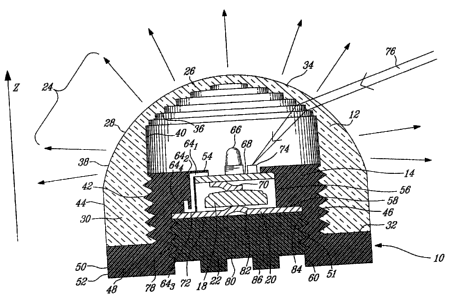
Referring now to Figures 4, 5A and 5B, an adjustable light emitting device,
generally referred to using the reference numeral 10, and in accordance with
an illustrative embodiment of the present invention will now be described.
Adjustable light emitting and receiving device 10 generally comprises an
electrically non conductive hollow cap 12, an electrically non conductive
casing
14, an electric load module such as a light module 16, a DC power source or
battery pack 18 comprising at least one battery such as a coin cell battery,
an
electrically conducting contact plate 20, and an electrically non conductive
plug
22. Though device 10 is presented here on its own, it will be obvious to a
person skilled in the art that the device may be coupled to various carrying
devices such as straps, belt clips, head gears and other items of the like
without departing from the general scope of the invention.
Still referring to Figures 4, 5A and 5B, and in accordance with an
illustrative
embodiment of the present invention, the hollow cap 12 is generally made of
molded, translucent, and electrically non-conductive plastic material such as
polycarbonate. The hollow cap is comprised of a closed dome 24, forming a
lens 26 at the top thereof and a generally annular diffusive region 28
therebelow, and a threaded cylindrical section 30 extending downwardly
therefrom to a cap base 32. The lens, illustrated here as a rounded stepped-
surface or Fresnel-type lens as described hereinabove, consists of a rounded
or spherical outer surface 34 and a cylindrically symmetric stepped inner
surface 36. The diffusive region, generally flowing downwardly from the above
lens, comprises a plurality of diffusive elements 38 on its outer surface,
such as
radial cuts, grooves or protrusions, and a cylindrical inner surface 40.
Cylindrical section 30 also comprises a series of threads 42 on its inner
surface, and a series of grip ribs 44 on its outer surface. Note that though
dome
24 is generally translucent, cylindrical section 30 need not be, and in some
CA 02577976 2007-02-12
-7-
applications, may be required to be opaque.
The one-piece casing 14 is generally made of opaque, molded and electrically
non-conductive plastic material. Viewed from the outside, the cylindrically
symmetric casing 14 generally comprises a hollow cylinder, defining a threaded
outer cylindrical surface 46 for engaging threads 42 of cap 12, coupled to an
annular foot 48 at the base thereof and extending radially outwards therefrom.
The peripheral face 50 of foot 48 may comprise a set of grip ribs 52. Viewed
from the inside, casing 14 presents a series inverted steps, starting with an
annular lip 54 extending radially inwards from the top of the casing, a first
inner
cylindrical wall 56 extending axially downwards from the base of lip 54, an
annular shoulder 58 extending radially outwards therefrom, and a second inner
cylindrical wall 60 extending axially downwards from the base of shoulder 58.
Inner cylindrical wall 60 is partially threaded with threads 62 for engaging
threads 64 of plug 22 (discussed hereinbelow).
The interior face of casing 14 further comprises a single continuous hook-
shaped channel 64 defined by consecutive channels 64, - 644: radial channel
64, extends across lip 54, axial channel 642 extends downwardly therefrom
along the first inner wall 56, shallow radial channel 643 extends outwardly
therefrom partly across annular shoulder 58, and short axial channel 644
extends upwardly therefrom within the body of casing 14.
The light module 16 comprises a light source 66 mounted centrally on a
circular
printed circuit board (PCB) 68. The light source is preferably a high-
intensity
light emitting diode (LED), which can provide high optical power outputs for
relatively low electrical power inputs. The selection of an appropriate light
source based on output (intensity), wavelength (IR, visible, broad spectrum,
etc) and durability for specific applications will be obvious to a person of
skill in
the art. PCB 68 is centrally mounted in casing 14 within first inner
cylindrical
wall 56 and rests under annular lip 54.
The light module 16 further comprises two contact members (terminals) 70 and
72. The first terminal 70 is generally spring loaded and is centrally coupled
to
CA 02577976 2007-02-12
-8-
the bottom of PCB 68 for connecting the top face of battery pack 18 to the
light
module. The second terminal 72 is peripherally coupled to the top of PCB 68,
and is generally hook-shaped for securely coupling itself within the hook-
shaped channel 64 of casing 14, thus securing light module 16 in place. As
will
be discussed hereinbelow, when plug 22 is fully screwed into casing 14, the
bottom of hook-shaped terminal 72 connects with contact plate 20, which is
itself in contact with the bottom of battery pack 18, to close the load
circuit.
Referring now to Figure 5C, an alternative illustrative embodiment of the
light
emitting and receiving device 10 is presented wherein the light emitting and
receiving device 10 is further comprised of a photosensor or photodetector 74
adapted for receiving and/or sensing an optical signal directed thereto. For
instance, the photodetector 74 may be annularly disposed on the PCB 68
around the LED 66, or again a plurality of photodetectors 74 may be disposed
thereat to detect a photosignal directed thereto by the translucent cap 12.
Circuitry for interpreting a signal generated by the photodetector(s) 74 may
be
combined within the PCB 68 to, for instance, activate the LED 66 upon
detection of an incoming optical signal, as in 76, to implement various device
programming and/or switching functions, and the like.
Referring now to Figure 6 in conjunction with Figures 5A and 5B, and in
accordance with an illustrative embodiment of the present invention, the one-
piece plug 22 is generally made of opaque, molded and electrically non-
conductive plastic material. The plug is generally disc-shaped and is sized to
fit
within the second inner cylindrical wall 60 of casing 14. It comprises an
upper
circular face that holds contact plate 20 thereon, a partially threaded
cylindrical
wall 78 extending axially downwards therefrom, and a circular base 80 at the
bottom thereof. Contact plate 20 is generally flat and circular, except
possibly
for a cylindrical/spherical protrusion 82 at its center for making contact
with the
bottom of battery pack 18 when the plug is in place. Cylindrical wall 78 is
partially threaded with threads 84, set to engage threads 62 of casing 14.
Finally, protruding tabs 86 extend axially and downwardly from circular base
80, providing screwing means for plug 22.
CA 02577976 2007-02-12
-9-
Referring now to Figure 7, and in accordance with an alternative embodiment
of the present invention, the adjustable light emitting device described
hereinabove may be slightly modified to make it waterproof, and thus practical
for applications where water may be an issue, such as in outdoor athletics,
water sports, diving, and other activities of the like. Essentially, resilient
sealing
"0" rings 88 and 90 are respectively used on both alternative plug 22' and
alternative cap 12' to provide a waterproof seal at respective junctions with
alternative casing 14'. For example, an annular channel 92 is set in
cylindrical
wall 78 of plug 22', just below threads 84, for partial insertion of sealing
ring 88
therein. As plug 22' is screwed into place, the sealing ring 88 is compressed
between the walls of channel 92 and the flat segment of cylindrical wall 60,
thus
sealing the interior of device 10 from below. To seal the device from above,
an
annular channel 94 is set at the bottom of cylindrical section 30 of
alternative
cap 12' for partial insertion of sealing ring 90 therein. As cap 12' is
screwed
down, sealing ring 90 is compressed between the walls of channel 94 and the
additional outer cylindrical wall 96 of alternative casing 14', thus sealing
the
interior of device 10 from above. Clearly, other sealing means may now be
obvious to one skilled in the art. Namely, the use of a double seal ring
configuration may be preferred for the adjustable cap in order to increase the
quality of the water seal. Suitable modifications to the sealing means may be
brought to the device in order to comply with specific sealing requirements.
The operation and activation of device 10, in accordance with an illustrative
embodiment of the present invention, will now be described with reference to
the above-cited illustrations. To activate the device, one must first secure
light
module 16 in place. This is accomplished by inserting the circular PCB 68
within cylindrical wall 56, aligning and securely coupling hook-shaped contact
54 within hook-shaped channel 64, and thus securely resting PCB 68 under
annular lip 54. A battery pack 18, which may include for example at least one
coin cell battery, is then provided and positioned within inner cylindrical
walls
56. Plug 22 is then screwed into place by engaging threads 84 of same with
threads 74 of casing inner wall 60, to shut the device from below. In the
alternative embodiment illustrated in Figure 7, sealing ring 88 is compressed
between the walls of channel 92 and inner wall 60 as the plug is screwed into
CA 02577976 2007-02-12
-10-
place, providing a water seal from below. If the plug is only partially
inserted,
the load circuit remains open as hook-shaped terminal 72 is not yet in contact
with contact plate 20 (though battery pack 18 may already be held in place
between contact 20 and spring-loaded terminal 70) and no light is emitted.
When the plug is fully screwed in, contact is finally made between the bottom
of
hook-shaped terminal 72 and contact plate 20, thus closing the load circuit
and
activating the device.
With specific reference to Figures 5A and 5B, and still in accordance with an
illustrative embodiment of the present invention, device 10 may be adjusted to
project light either directionally forward in the positive z direction, as
illustrated
in Figure 5B (directional mode), or hemispherically, as illustrated in Figure
5A
(omnidirectional mode). In either mode, cap 12 is at least partially screwed
onto
casing 14 by engaging threads 42 and 46 of the cap and casing respectively. In
the alternative embodiment illustrated in Figure 7 (omnidirectional mode),
sealing ring 90 is compressed between the walls of channel 94 and wall 96 of
alternative casing 14' to provide a water seal from above.
As the cap is screwed down onto the casing in the negative z direction, the
distance between the lens 26 and the light source 66 is progressively reduced.
As discussed hereinabove, the distance between the light source and the lens
will define the directionality of the light emitted by the device. If the cap
is only
screwed in slightly to maintain a distance between the light source and the
lens
approximately equal to the focal length of the lens (Figure 5B), light will be
projected substantially directionally in the positive z direction.
Alternatively, if
the cap is screwed in fully so to rest cap base 32 on top of foot 48 (Figure
5A),
light will be divergently projected by the lens, and light emitted radially by
the
source will be scattered by diffusive elements 38, which will somewhat
homogenize the omnidirectionality of the device in this mode.
Consequently, device 10 can provide both directional and omnidirectional
illumination by simple adjustment of cap 12. Also, as discussed hereinabove
with reference to Figure 5C, the device may further comprise one or more light
sensors 74 adapted for sensing and reacting to an incoming optical signal 76,
CA 02577976 2007-02-12
-11-
even when such a signal is projected on the device 10 from an angle. Circuitry
coupled to the PCB 68 or independently disposed within the device 10, may
react to the signal generated by the light sensor 74 upon detection of the
incoming optical signal 76 to perform various tasks that may include
activating
the LED 66 momentarily, switching the device ON or OFF, switching various
illumination functions (pulsed illumination, continuous illumination,
illumination
wavelength when plural LEDs are used, etc.) and the like. In addition, by
adjusting the axial position of the cap 12, a device's ability to detect the
incident
beam 76 as a function of the beam's angle of incidence may be varied.
A person of skill in the art will understand that other permutations and
configurations may also be considered without departing from the general
scope and nature of the present embodiment. Namely, the device 10 may be
configured such that functions associated with the detection of incoming
signals
are not correlated with light emitting functions, or again, separate light
emitting
and light sensing devices may be considered.
It will also be apparent to a person skilled in the art that the substitution
of the
rounded stepped-surface lens illustrated in the above illustrative embodiments
for a standard substantially flat Fresnel lens, as discussed hereinabove with
reference to Figures 2A and 2B, or again for a modified rounded Fresnel-type
lens, will not alter the general functionality of the device. Namely, one may
opt
to combine a flat Fresnel lens with a series of radial diffusive elements to
achieve a same goal, while providing a generally flat, rather than rounded
device.
Referring now to Figures 8A and 8B, a further alternative illustrative
embodiment of the present invention is presented wherein an alternative
adjustable light emitting device 100 is fitted with a modified Fresnel-type
lens
102. The device 100, much like the device 10, is generally comprised of a
translucent electrically non conductive cap 104 portion and a threaded portion
106 for mounting the lens 102 onto an inner casing (not shown) within which is
mounted about a light source 108, such as a LED. Batteries, switches and
circuitry (also not shown) for the activation of the LED 108 and operation of
the
CA 02577976 2007-02-12
-12-
device 100 are also included and should be apparent to a person of skill of
the
art upon reference to the above description of device 10.
The cap 104, much like the cap 12 of device 10 (Figure 5), is generally molded
of a translucent plastic material such as translucent polycarbonate to define
the
Fresnel-type lens 102 in a top portion thereof. As discussed hereinabove with
reference to Figures 5A and 5B, the cap 104 may be adjusted axially to vary
the dispersion of the light transmitted therethrough. As with device 10, when
the cap 104 is axially adjusted away from the casing, light generated by the
device 100 is emitted directionally (directional mode), whereas when the cap
104 is axially adjusted toward the casing, light generated by the device 100
is
emitted hemispherically (omnidirectional mode). As will be apparent to a
person
of skill in the art, intermediate positions of the cap 104 will provide a
progressively variable combination of directional and omnidirectional
emissions.
In this embodiment, however, the lens 102 is generally comprised of a series
of
progressively inwardly curving steps, as in 110, moulded or otherwise formed
on the inner surface of the lens 102. Unlike the squared stepped surface
structure of lens 24 (see Figure 5), the inwardly curving steps 110 are
progressively rounded inwardly to define, at the apex thereof, a rounded inner
dome surface 112. This modified structure provides improved light dispersion
and dissipation characteristics when the device 100 is used in an
omnidirectional mode while maintaining effective collimating characteristics
in a
directional mode.
Referring now to Figure 9A in addition to Figure 8B, the dispersion of light
by
an LED is typically oriented such that a region of maximum intensity is
achieved directly above the apex 114 of the LED 108 with the intensity of
emitted light falling off quickly as one moves away from the apex 114.
Referring
now to Figure 9B in addition to Figure 8B, when the lens 104 is placed over
the
LED 108 illustratively having the light dispersal characteristic as
illustrated in
Figure 9A, intensities of emitted light as measured as one moves from the apex
116 of the lens 104, which is incidentally co-aligned with the apex 114 of the
CA 02577976 2007-02-12
-13-
LED 108, where intensities are the highest, to a wide angled position where
intensities are lowest, vary relatively progressively and smoothly across the
device's entire illumination field. In particular, although the intensity
measured
at the apex 116 of the lens 104 is still greater than elsewhere, the ratio of
the
intensities measured over the upper hemisphere of the lens 104 versus the
intensity measured at the apex 116 are within a minimum percentage of the
maximum intensity, illustratively about 50%. This is a particularly
advantageous
feature for lights to be used in conjunction with life saving devices as the
projection of light over a wider range will increase the chances of
recognition,
These improved illumination characteristics are generally attributed to the
optimized disposition, roundness and curvature of the steps 110, the above
being designed to offer a smoother control of light being transmitted and
diffracted by the lens 102.
In the present example, the design of lens 102, that is the general
disposition,
roundness and curvature of steps 108, is suited for use with a wide angle
surface mounted LED or bulb 108 (e.g. 120 rated bulb). As such, when the
device 100 is used in omnidirectional mode with a wide angle bulb 108, a
substantially smooth and progressive hemispherical light distribution may be
attained to provide a substantially full hemispherical illumination.
Combination
of lens 102 with other types of light sources may also provide similar
smoothing
and progressive dispersion effects.
A person of skill in the art will understand that other types and variations
of lens
designs may be considered to modify the operative characteristics of the above
light emitting devices without departing from the general scope and nature of
the present disclosure. Namely, the general disposition, roundness and/or
curvature of the steps 108 may be optimized to produce similar effects with
different types of light sources. Also, by optimizing the dispersion and
dissipation of light when the device is used in omnidirectional mode by
adjusting the general shape and configuration of the stepped-surface or
Fresnel-type lens (26, 102), one may chose not to include diffusive elements,
as in 38 in Figure 4, as hemispherical illumination may be sufficiently
achieved
CA 02577976 2007-02-12
-14-
by the modified lens alone. As will be understood by a person of skill in the
art,
the inclusion of diffusive elements, as in 38, may or may not be used in any
design of devices 10 or 100 without modifying the general scope and nature of
the present disclosure. Furthermore, specific lens designs to be used with
different types of light sources for different applications where specific
illumination characteristics and requirement may vary should also be apparent
to a person of skill in the art.
Also, one may opt to include a rounded or spherical reflector in the device,
as
discussed hereinabove with reference to Figure 3, to maximize the output of
the device without altering its general functionality and operability.
Finally, one
of skill in the art will appreciate that the above illustrative embodiments
may be
modified in structure to accommodate various carrying means, such as straps,
clips, belts, and other features of the like, required to customize the
illustrated
device for different applications.
While this invention has been described with reference to the illustrative
embodiments, this description is not intended to be construed to a limiting
sense. Various modifications or combinations of the illustrative embodiments,
as well as other embodiments of the invention, will be apparent to persons
skilled in the art upon reference to the description. It is therefore intended
that
the described invention encompass any such modifications or embodiments.