Note: Descriptions are shown in the official language in which they were submitted.
CA 02578120 2007-02-23
WO 2006/026509 PCT/US2005/030564
ARTIFICIAL SPHINCTER
CROSS-REFERENCE
This application claims the benefit of U.S. Provisional Application No.
60/604,723, filed August 25,
2004, which is incorporated herein by reference in its entirety.
Field of the Invention
This invention relates to artificial sphincters, such as urinary, fecal and
gastric sphincters, and methods
of using the same.
Back round
It is estimated that over 12 million Americans have urinary incontinence.
Incontinence affects all ages,
both sexes, and people of every social and econonuc level. It is also
estimated that 15 to 30 percent of people
over the age of 60 have incontinence. Women are twice as likely as men to have
this condition. In addition, at
least half of the 1.5 million Americans who reside in nursing homes are
incontinent. The exact number of
people with incontinence is not known, but the total number of people affected
may be far greater than current
estimates. Incontinence is a symptom that can be caused by a wide variety of
conditions. Some of these causes,
such as urinary tract or vaginal infections, medicine effects, or
constipation, may be temporary. In addition, to
urinary incontinence, fecal incontinence and reflux diseases are common
disorders caused by malfunctioning
sphincters.
Artificial sphincters that are in the market today have several components
like pump, fluid reservoir,
cuff, one-way valves and the tubing that connects the reservoir, pump and the
cuff. It is not very comfortable
for the patient to use these systems. Erosion, fluid loss, pressure loss, etc.
compromise the effectiveness of the
artificial sphincters over-time. Hence, there is a need to develop novel
sphincters for use in disorders caused by
the malfunction of natural sphincters in the body.
SUMMARY OF THE INVENTION
The invention provides artificial sphincters and methods of use thereof. The
artificial sphincter
comprises a support and an electroactive polymer element for placement around
a body cavity. The artificial
sphincter can be used around several body cavities, including the urethra and
various parts of the gastro-
intestinal tract. The sphincter system allows for opening and/or closing of
the body cavity around which it is
placed, this opening and closing being controlled by the activation of the
electroactive polymer element with
electrical signals. The artificial sphincter system can also include a sensor
to sense the state of the body cavity it
surrounds to provide signals for activation or inactivation of the
electroactive polymer element.
A first aspect of the invention is an artificial sphincter comprising an
electroactive polymer element
and a support, both of which being configured to allow the constriction of a
body cavity between the
electroactive polymer element and the support. The artificial sphincter is
useful for constriction of various body
cavities, including the urethra to treat urinary incontinence; the esophagus
to treat reflux disease, and the rectum
to treat fecal incontinence. The sphincter further comprises electrical
terminals contacting the electroactive
polymer element for modulating the shape of the electroactive polymer element.
The support can be rigid or
semi-rigid such as to provide a certain amount of stiffness for constricting
the body cavity between the
electroactive polymer element and the support.
CA 02578120 2007-02-23
WO 2006/026509 PCT/US2005/030564
Preferably, the artificial sphincter comprises a support in the form of an
enclosure with a lumen, for
placement around a body cavity, and an electroactive polymer element. The
enclosure can also include a soft
elastomeric layer around the lumen.
In some embodiments, the artificial sphincter includes a control unit for
electrically controlling the
electroactive polymer element to open or close the body cavity. The action of
the artificial sphincter of the
present invention can be controlled using a variety of control units, for
example, (a) power source and a simple
switch or (b) power source and a logic/control device such as a computer. The
artificial sphincters of the
present invention can also comprise a sensing system (such as a system
comprising strain gauges) for sensing
the degree of deformation of the electroactive polymer element.
In one embodiment of the invention, the artificial sphincter has a rigid
enclosure with a through-lumen
with soft elastomeric layer, an electroactive polymer element, power switch,
leads and a power source.
Optionally there is a deformable element, such as a compression spring, inside
the enclosure. The deformable
element pushes the elastomeric layer outward to keep the through-lumen closed.
One end of the electroactive
polymer element is in between the deformable element and the elastomeric
layer, and the other end is secured
inside the enclosure to a terminal block. The terminal block is connected to
the power source through lead wires
via a switch. The sphincter is placed around a body cavity, such as the
urethra, and the soft elastomeric layer
comes in contact with the wall of the body cavity, such as the urethra wall.
At rest, the polymer element is not
charged and the body cavity, such as the urethra, remains closed. When the
power is delivered by depressing
the switch, the polymer element deflects inward and activates the deformable
element, thus allowing the body
cavity, such as the urethra, to open in order to empty the bladder. When the
power is stopped, the polymer will
lose its charge and lose the strength to keep the deformable element
activated. The deformable element returns
to its normal state and again closes the body cavity.
In one embodiment of the invention, the power source and the switch are
implanted in the patient's
body just beneath the outer skin. This embodiment may also include a battery
recharging mechanism implanted
in the patient's body. In another embodiment of the invention, the power
source is outside the patient's body and
the power is transmitted transcutaneously through the induction coil that is
implanted in the patient's body. In
another embodiment of the present invention, the actuator used is a
superelastic shape memory alloy like
Nitinol.
In one embodiment, the invention comprises of a biologically implantable
artificial sphincter
comprising an electroactive polymer element; a support; and a conduit having a
first side and a second side;
wherein electroactive polymer element is on the first side of the conduit.
Preferably, the support is on the
second side of the conduit and the first side of the conduit is substantially
opposite to the second side of the
conduit. The conduit can be circumscribed by an elastomeric sheath.
Preferably, the electroactive polymer element comprises an ion-exchange
polymer metal composite.
The electroactive polymer element can be in the shape of a panel, which is
substantially flat or in the shape of a
spring. The sphincter can further comprise a deformable element, such as a
compression spring, which is in
mechanical communication with the electroactive polymer element. Preferably,
the sphincter also includes a
power supply in electrical communication with the electroactive polymer
element and a switch.
A second aspect of the invention, is a method of opening and/or closing a body
cavity using an
artificial sphincter described herein. For example, one embodiment is a method
of treating urinary incontinence
-2-
CA 02578120 2007-02-23
WO 2006/026509 PCT/US2005/030564
using an artificial sphincter comprising implanting the artificial sphincter
around the urethra; closing the urethra
with mechanical spring force in the artificial sphincter; and opening the
urethra by transmitting an electrical
signal to the artificial sphincter; wherein opening the urethra comprises the
electrical signal actuating an
electroactive polymer element in the artificial sphincter. Preferably, the
closing of the urethra is via constricting
the urethra between the electroactive polymer element and a support. The
urethra can be closed by not
transmitting electricity to the electroactive polymer element and opened by
using a mechanical spring force to
pull the electroactive polymer element away from the urethra. The artificial
sphincters described herein can also
be used for the treatment of fecal incontinence and reflux diseases.
The artificial sphincter cuffs of the present invention may be adapted for
placement around a number of
body lumens, including the urethra, the anal canal, and the lower esophagus.
One embodiment of the invention is an artificial sphincter comprising an
electroactive polymer element
and a support, said electroactive polymer element and support being configured
to constrict a body cavity
disposed there-between. The support of the sphincter can be an encapsulating
device with one passage for a
body organ. This passage can be substantially circumscribed by a sheath. The
electroactive polymer element
can be a substantially flat surface or a spring. This embodiment can fizrther
a spring in mechanical
communication with the electroactive polymer element. The sphincter also
includes a power supply in electrical
communication with the electroactive polymer element.
Another embodiment of the invention is an implantable control device
comprising an electroactive
polymer actuator, an enclosure, and a power management device; wherein the
enclosure is configured to
encompass a body cavity, the electroactive polymer actuator and the enclosure
are configured to constrict the
body cavity, and the power management device is adapted to connect to the
electroactive polymer actuator.
The devices disclosed herein can be coated with materials to prevent or
promote tissue growth. Also,
the devices can include an inductive coupling mechanism adapted to connect the
electroactive polymer to a
power source. The body cavities regulated by the sphincters disclosed herein
include urethra, lower esophagus,
lower gastro-intestinal tract, or rectum.
Another embodiment of the invention is a method of controlling passage of
contents across a body
cavity comprising implanting a control device around a body cavity, the device
comprising an electroactive
polymer actuator, an enclosure, and a power management device; controlling a
flow of contents in the body
cavity, this control being performed by constricting and unconstricting of the
body cavity between the
electroactive polymer actuator and the enclosure. In this method control of
flow of contents in the body cavity
can be in response to transcutaneous feedback from the body cavity, said
feedback being related to the contents
in the body cavity. The control device described herein can be controlled with
an inductive coupling
mechanism. The inductive coupling mechanism can be transcutaneous.
The devices described herein are suitable for the treatment of several
disorders such as disorders of the
urethra, lower esophagus, lower gastro-intestinal tract, or rectum. One
embodiment is a method of treating a
disease using an artificial sphincter comprising implanting an artificial
sphincter around a body cavity, the
artificial sphincter comprising an electroactive polymer element and a
support; closing the body cavity with the
artificial sphincter by applying a mechanical force on the body cavity between
the support and the electroactive
polymer element; and opening the body cavity by transmitting an electrical
signal to the electroactive polymer
-3-
CA 02578120 2007-02-23
WO 2006/026509 PCT/US2005/030564
element. This method can be used in the treatment of urinary incontinence,
fecal incontinence, or reflux
diseases.
INCORPORATION BY REFERENCE
All publications and patent applications mentioned in this specification are
herein incorporated by
reference to the same extent as if each individual publication or patent
application was specifically and
individually indicated to be incorporated by reference.
BRIEF DESCRIPTION OF THE DRAWINGS
The novel features of the invention are set forth with particularity in the
appended claims. A better
understanding of the features and advantages of the present invention will be
obtained by reference to the
following detailed description that sets forth illustrative embodiments, in
which the principles of the invention
are utilized, and the accompanying drawings of which:
Figures 1A and 1B illustrate a male and female urinary system.
Figures 2A and 2B illustrate an embodiment of the artificial sphincter system
in use in a female and a
male urinary system.
Figures 3A-3D illustrate embodiments of the artificial sphincter system.
Figure 4 illustrates an embodiment of the artificial sphincter system.
Figure 5 illustrates a cross-sectional view of the upper gastro-intestinal
tract.
Figure 6 illustrates an embodiment of the artificial sphincter system in use
in upper gastro-intestinal
tract.
Figure 7 illustrates a cross-sectional view of the lower gastro-intestinal
tract.
Figure 8 illustrates a cross-sectional view of an embodiment of the artificial
sphincter in use in a lower
gastro-intestinal tract.
Figure 9 illustrates an embodiment of an inductive coupling system associated
with the artificial
sphincter system.
Figure 10 illustrates an embodiment of an inductive coupling system associated
with the artificial
sphincter system.
DETAILED DESCRIPTION OF THE INVENTION
While preferred embodiments of the present invention have.been shown and
described herein, it will be
obvious to those skilled in the art that such embodiments are provided by way
of example only. Numerous
variations, changes, and substitutions will now occur to those skilled in the
art without departing from the
invention. It should be understood that various alternatives to the
embodiments of the invention described
herein may be employed in practicing the invention. It is intended that the
following claims define the scope of
the invention and that methods and structures within the scope of these claims
and their equivalents be covered
thereby.
ARTIFICIAL SPHINCTER SYSTEM
Figures lA and IB depict the male and female urinary system. Some of the
components of a male
urinary system, as depicted in Fig. lA, are the urinary bladder 1, prostate
gland 3, urinary sphincter muscle 2,
-4-
CA 02578120 2007-02-23
WO 2006/026509 PCT/US2005/030564
urethra 4, and scrotum 9. The components of a female urinary system, as
depicted in Fig. 1B, are the urinary
bladder 1, uterus 8, urinary sphincter muscle 2, and urethra 4.
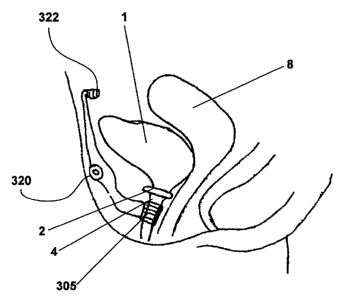
Figure 2A illustrates an embodiment of an artificial sphincter system 300
implanted in a female subject.
The artificial sphincter system 300 discussed herein comprises of the
artificial sphincter 305 or 400 and an
inductive coupling system 900 such as depicted in Figure 9 and 10. The
artificial sphincter system in the female
subject is siniilar to the artificial sphincter system shown for the male
subject in Figure 2B. In the illustrated
embodiment, in Figures 2A and 2B, the artificial sphincter 305 is controlled
with a switch 320 and a power
source 322. The switch and power source may be located inside or outside the
body.
Figure 2B illustrates an embodiment of an artificial sphincter system 300
implanted in a male subject.
The subject has a bladder 1, a sphincter muscle 2, a prostate gland 3 and a
urethra 4. As depicted, the artificial
sphincter system 300 has an artificial sphincter 305, a switch 320, and a
power source 322. The switch 320
and/or power source 322 can be connected to the artificial sphincter 305.
Figures 3A-3D depict two embodiments of an artificial sphincter system.
Figures 3A and 3B depict an
embodiment of an artificial sphincter 305 with a support 302 and an enclosure
302' containing the electroactive
polymer element 308. The electroactive polymer element 308 has electric
contacts 310. The support302,
enclosure 302', and electroactive polymer element 308 are configured and
adapted to constrict and unconstrict a
body cavity 40. In the normal state depicted in Figure 3A, the electroactive
polymer element 308 is not
activated and leaves the body cavity 40 open, i.e., unconstricted. In the
actuated state in Figure 3B, the
electroactive polymer element 308 is activated by the electrical contacts 310
and closes the body cavity 40', i.e.,
constricted. Examples of body cavities around which the artificial sphincter
system 300 can be used include the
urethra and gastro-intestinal cavities, such as the esophagus, the large
intestine and the rectum. In other
embodiments, the body cavity 40 can be constricted by the electroactive
polymer element 308 when it is in its
normal, non-activated state and the body cavity can be opened when the
electroactive polymer element 308 is
actuated by activation by the electrical contacts 310. The support 302 and the
enclosure 302' can be configured
as a single piece or as multiple pieces.
Figures 3C and 3D illustrate a cross-sectional view of the artificial
sphincter 305 that is configured to
close the body cavity 40 when it is at rest: Artificial sphincter 305 at rest
is depicted in Figure 3D. The artificial
sphincter 305 has a support 302 and an electroactive polymer element 308. The
support 302 is an enclosure
such as an outer shell with a lumen or a clam shell with a lumen or just a
support. The support is rigid or is
semi-rigid such as to provide a certain amount of stiffness for constricting
the body cavity 40 between the
electroactive polymer and the encapsulating device. As shown in Figure 3C and
3D, the artificial sphincter 305
includes a soft elastomeric layer 304, a deformable element 306, such as the
compression spring shown in
Figures 3C and 3D, an actuator such as an electroactive polymer (EAP) element
308, and a power supply
termina1310. Figure 3C illustrates a cross-sectional view of the artificial
sphincter 305 that is configured to
open up the body cavity 40 when activated.
In the embodiment depicted in Figure 3C and 3D, the body cavity 40 is closed
when there is no
electrical current applied to the EAP element 308. In this state, as depicted
in Figure 3D, the deformable
element applies mechanical force on the EAP element 308, and the body cavity
40' is constricted closed
between the EAP element 308 and the support 302. When electrical current is
applied on the EAP element 308,
as depicted in Figure 3C, the EAP element 308 is deflected away from the body
cavity 40 and the body cavity
-5-
CA 02578120 2007-02-23
WO 2006/026509 PCT/US2005/030564
40 is opened. In an alternative embodiment of the artificial sphincter system
305, the body cavity 40' is closed
when electrical current is applied to the EAP element 308, and the EAP element
308 constricts the body cavity
40 closed between itself and the support 302. The body cavity, in this
embodiment, is opened when the
electrical current is not applied to the EAP element 308, and the EAP element
moves away from the body cavity
40 to unconstrict it and thus open it up.
The electroactive polymer element 308 has two power supply terminals 310. The
power supply
terminals 310 (e.g., an anode and a cathode) connect to the surface of the EAP
element 308. When the EAP
element 308 is activated, the EAP element 308 deforms. In the embodiments
shown in Figures 3C and 3D, the
deformation of the EAP element 308 activates the deformable element 306. The
activation of the deformable
element 306, such as a compression spring, removes the constriction pressure
from the body cavity 40' and
allows the body cavity 40 to open. The open body cavity 40 allows contents of
the body cavity, such as urine or
feces, to pass through the body cavity 40. When the body cavity 40 is empty,
removing the charge to the EAP
element 308 allows the deformable element 306 to relax. The relaxed deformable
element 306 closes (e.g.,
constricts) the body cavity 40, for example, against a support such as the
inside of the support 302. Support 302
may be covered with an elastomer or a biocompatible and/or non-abrasive
coating.
In some embodiments, the EAP element 308 is an ion-exchange polymer metal
composite (IPMC).
The element 308 is encapsulated in the outer shel1302. The outer she11302 has
one or more openings. A
conduit is defined between the openings. The body cavity 40 passes through the
openings and the conduit, and
the outer she11302. The artificial sphincter 305 is configured so the EAP
element 308 does not directly contact
the body cavity 40'. The elastomeric layer 304 separates the EAP element 308
from the body cavity 40. The
EAP element 308 is single layered or multi-layered.
The elastomeric layer 304 can be made of silicone, latex, polychloroprene
(e.g., neoprene), fully
vulcanized thermoplastic rubbers (TPRs) such as polyolefin-based or styrene-
based rubbers (e.g., Alcryn from
Dupont, Kryton(R from Shell, Santoprene from Monsanto), thermoplastic
elastomers (TPEs) such as polyester
TPEs or nylon TPEs (e.g., Hytel from Dupont, Lomod from GE, Pebax from Elf
AtoChem) or any other
thermoplastic or thermosetting plastic polymer.
In some embodiments, the artificial sphincter is controlled with a
transcutaneous energy transmission
system (TETS) and/or a processor. The TETS transmitter coil (not shown) would
preferably be located outside
the body. The processor is configured to control the artificial sphincter and
also sense and/or process other
relevant information necessary for control of the body cavity, such as the
urethra.
In some embodiments, a power supply 322 (e.g., a battery) and an ON/OFF switch
320 are implanted
in the subject. The power supply 322 and the switch 320 can be anywhere in the
subject that is convenient to
the subject. Wires connect the power supply 322, the switch 320 and the
artificial sphincter 305. In other
embodiments, the power supply 322 is outside the body of the subject. In such
embodiments power can be
transmitted to the artificial sphincter 305 using a transcutaneous energy
transfer system (TETS), for example a
system that inductively transmits energy (i.e., similar to methods for
delivering power to artificial hearts).
Figure 9 depicts an inductive coupling system that is suitable for controlling
the artificial sphincter 305
which includes a connecting element 906 (which connects the electrical
contacts 310 to the rest of the electrical
system), a connector 901, a energy source 322, a sensor 903, a timer 904, and
a controller 905. The connector
-6-
CA 02578120 2007-02-23
WO 2006/026509 PCT/US2005/030564
901, energy source 322, sensor 903, a timer 904, and controller 905 are
located in a housing disposed in a region
outside or inside the body.
Figure 10 depicts one embodiment of an electrical system 900 associated with a
EAP element 308. The
inductive coupling system 900 has an implanted portion 150 and a non-implanted
portion 160. The implanted
portion 150 is a closed circuit with the first inductor 102 in series with a
first capacitor 101 and the EAP element
308. The EAP element 308 is attached to the closed circuit of the implanted
portion 150 by electrical contacts
310. The implanted portion is a closed circuit and can have a resistor (not
shown). The non-implanted portion
160 has a second inductor 102' that is in series with a resistor 107, the
power supply 322, and a second capacitor
101'. The capacitors, resistors, and, in part, the inductors are
representative of the electrical characteristics of
the wire of the circuit and are not necessarily representative of specific
elements. The implanted portion 150 is
within tissue and has a tissue surface 104 nearby. The non-implanted portion
is in insulation niaterial 103. An
air interface 105 is between the tissue surface 104 and the insulation
material 103.
The power supply 322 can be a power cell, a battery, a capacitor, a
substantially infinite bus, a portable
generator, or combinations thereof. The power supply typically has a power
output of from about 1mA to about
5A. The connecting element 906 is a wire lead, an inductive energy transfer
system, a conductive energy
transfer system, a chemical transfer system, an acoustic or otherwise
vibratory energy transfer systeni, a nerve or
nerve pathway, other biological tissue, or combinations thereof. The
connecting element is made from one or
more conductive materials, such as copper. The connecting element is
completely or partially insulated andlor
protected by an insulator, for example polytetrafluoroethylene (PTFE). The
insulator is typically biocompatible.
The power supply 322 is in electrical communication with the EAP element 308
through a connecting element.
The connecting element is attached to the electrical contacts 310.
In other embodiments, the EAP element 308 can be wrapped around the body
cavity 40 and use the
deformable element 306, such as compression springs, in series. Using the EAP
element 308 in series with the
compression spring 306 can achieve the same function as the configuration
described supra and in Figures 3A-
3D.
The EAP element 308 and the surface of any other elements described herein can
be coated with
materials and/or agents to promote tissue growth around the coated surfaces.
The EAP element 308 and the
surface of any other elements described herein can be coated with materials
and/or agents to eliminate and/or
prevent tissue growth around the coated surfaces.
The actuator can be a superelastic Nitinol material instead of an IPMC. The
actuator can be a leaf
spring. The actuator can be in the artificial sphincter without the deformable
element 306 attached to the
actuator.
The artificial sphincter can be controlled with a sensor and a controller to
open and close the body
cavity, such as the urethra. The controller can be a programmable device to
open and close the body cavity via
the electroactive element of the artificial sphincter. The sensor can be a
pressure sensing device that can sense
the pressure in the body cavity, such as urinary bladder or gastro-intestinal
tract, and send a signal to the
controller.
Another embodiment of the artificial sphincter 400 is shown in Figure 4. This
embodiment comprises
a clam-shell shaped enclosure 401, support 402, a lumen for the body cavity
403, and an electroactive polymer
element 404. The support 402 can be rigid or semi rigid, the rigidity level
being such that it allows for
-7-
CA 02578120 2007-02-23
WO 2006/026509 PCT/US2005/030564
constriction of the body cavity by the support 402 and the electroactive
polymer element 404. Figure 4 depicts
the artificial sphincter 400 with a wall removed so as to view the interior of
the device. Preferably, the device is
a single piece along with the top (which is not shown). The artificial
sphincter 400, typically, includes a hinging
mechanism to allow its placement around a body cavity. The two ends of the
clam-shell shaped enclosure 401
can come around to meet to provide a snug fit around the body cavity, which
would be present in the lumen 403.
The clam-shell shaped enclosure 401 and support 402 can be made of different
materials. Further, the clam-
shell shaped enclosure 401 and support 402 can be one continuous piece or can
be separate pieces. The artificial
sphincter 400 controls the constriction of the body cavity present in lumen
403 by the movement of the
electroactive polymer element 404 towards the support 402 such that mechanical
force is applied on the body
cavity present in lumen 403.
Figure 5 depicts the upper gastro-intestinal tract with the esophagus 10,
lower esophagus sphincter 15,
diaphragm 11, stomach 13, liquid contents 12, and pylorus 14. Figure 6 depicts
the use of an artificial sphincter
system 300 or 400 in the esophagus for the treatment of reflux disorders with
the artificial sphincter 305 and
switch 320.
Figure 7 depicts the lower gastro-intestinal tract with the rectum 20,
exterior sphincter 21, and interior
sphincter 22. Figure 8 depicts the use of an artificial sphincter system 300
or 400 in the rectum for the treatment
of fecal incontinence with the artificial sphincter 305 and switch 320.
The devices described herein maybe implanted with or without sutures or other
bonding material such
as surgical glue. The devices in some embodiments have external fibers or
surface pores or coatings, such as
protein based coatings like poly-L-lysine and poly-D-lysine, to promote tissue
in-growth and help affix the
device to adjacent tissue. In other embodiments, the devices are coated with
material to prevent tissue growth
around the implanted device, such as hyaluronic acid.
U.S. Patent No. 6,749,556 to Banik is hereby incorporated by reference in its
entirety.
METHODS OF MAKING EAP ELEMENT
In some embodiments, the EAP element 308 is an IPMC strip which is made from a
base material of an
ionomer sheet, film or membrane. The ionomer sheet is formed using ionomer
dispersion.
IPMC is made from the base ionomer of, for example, polyethylene,
polystryrene,
polytetrafluoroethylene, polyvinylidene fluoride (PVDF) (e.g., KYNAR and
KYNAR Flex , from
ATOFINA, Paris, France, and SOLEF , from Solvay Solexis S.A., Brussels,
Belgium), hydrophilic-PVDF (h-
PVDF), polyfluorosulfonic acid based membranes like NAFION (from E.I. Du
Point de Nemours and
Company, Wilmington, DE), polyaniline, polyacrylonitrile, cellulose, cellulose
acetates, regenerated cellulose,
polysulfone, polyurethane, and combinations thereof. The conductive material
that is deposited on the ionomer
can be gold, platinum, silver, palladium, copper, graphite, conductive carbon,
or combinations thereof.
Conductive material is deposited on the ionomer either by electrolysis
process, vapor deposition, sputtering,
electroplating, or combination of processes.
The IPMC is cut into the desired implant shape for the EAP element 308. The
electrical contact 310
(e.g., anode and cathode wires for EAP element) is connected to the IPMC
surfaces by, for example, soldering,
welding, brazing, potting using conductive adhesives, or combinations thereof.
The EAP element 308 is
configured, if necessary, into specific curved shapes using mold and heat
setting processes.
-8-
CA 02578120 2007-02-23
WO 2006/026509 PCT/US2005/030564
In some embodiments, the EAP element 308 is insulated with electrical
insulation coatings. Also, the
EAP element 308 can be insulated with coatings that promote cell growth and
minimize fibrosis, stop cell
growth, or kill nearby cells. The insulation can be a biocompatible material.
The EAP element 308 is coated
with polymers such as polypropylene, poly-L-lysine, poly-D-lysine,
polyethylene glycol, povinyl alcohol,
polyvinyl acetate, polymethyl methacrylate, or combinations thereof. The EAP
element 308 can also be coated
with hyaluronic acid. The coating is applied to the device by standard coating
techniques like spraying,
electrostatic spraying, brushing, vapor deposition, dipping, etc.
In one example, a perfluorosulfonate ionomer, PVDF or h-PVDF sheet is prepared
for manufacturing
the EAP element 308. The sheet is roughened on both sides using, for example,
about 320 grit sand paper and
then about 600 grit sand paper. The sheet is then rinsed with deionized water.
The sheet is then submerged in
isopropyl alcohol (IPA), and subjected to an ultrasonic bath for about 10
minutes. The sheet is rinsed with
deionized water. The sheet is then boiled for about 30 minutes in hydrochloric
acid (HCL). The sheet is rinsed
and then boiled in deionized water for about 30 minutes. The sheet is then
subject to ion-exchange (i.e.,
absorption). The sheet is submerged into, or otherwise exposed to, a metal
salt solution at room temperature for
more than about three hours. Examples of the metal salt solution are
tetraammineplatinum chloride solution,
silver chloride solution, hydrogen tetrachloroaurate, tetraanuninepalladium
chloride monohydrate or other
plantinum, gold, silver, carbon, copper, or palladium salts in solution. The
metal salt solution typically has a
concentration of greater than or equal to about 200mg/100m1 water. 5%
anunonium hydroxide solution is added
at a ratio of 2.5m1/100ml to the tetraammineplatinum chloride solution to
neutralize the solution. The sheet is
then rinsed with deionized water. A primary plating is then applied to the
sheet. The sheet is submerged in
water at about 40'C. A 5% solution by weight of sodium borohydride and
deionized water is added to the water
submerging the sheet at 2m1/180m1 of water. The solution is stirred for 30
minutes at 40'C. The sodium
borohydride solution is then added to the water at 2m1/180m1 of water and the
solution is stirred for 30 minutes
at 40'C. This sodium borohydride adding and solution stirring is performed six
times total. The water
temperature is then gradually raised to 60'C. 20m1 of the sodium borohydride
solution is then added to the
water. The solution is stirred for about 90 minutes. The sheet is then rinsed
with deionized water, submerged
into 0.1N HCI for an hour, and then rinsed with deionized water.
In some embodiments, the sheet receives a second plating. The sheet is
submerged or otherwise
exposed to a tetraammineplatinum chloride solution at a concentration of about
50mg/100m1 deionized water.
5% ammonium hydroxide solution is added at a rate of 2m1/100m1 of
tetrammineplatinum chloride solution. 5%
by volume solution of hydroxylamine hydrochloride in deionized water is added
to the tetraammineplantium
chloride solution at a ratio of 0.1 of the volume of the tetraammineplatinum
chloride solution. 20% by volume
solution of hydrazine monohydrate in deionized water is added to the
tetraammineplatinum chloride solution at
a ratio of 0.05 of the volune of the tetraammineplantinum chloride solution.
The temperature is then set to about
40'C and the solution is stirred.
A 5% solution of hydroxylamine hydrochloride is then added at a ratio of
2.5m/100m1 of
tetraammineplatinum chloride solution. A 20% solution of hydrazine monohydrate
solution is then added at a
ratio of 1.25m1/100ml tetraammineplatinum chloride solution. The solution is
stirred for 30 minutes and the
temperature set to 60'C. The above steps in this paragraph can be repeated
three additional times. The sheet is
then rinsed with deionized water, boiled in HCl for 10 minutes, rinsed with
deionized water and dried.
-9-
CA 02578120 2007-02-23
WO 2006/026509 PCT/US2005/030564
In some embodiments, the polymer base is dissolved in solvents, for example
dimethyl acetamide,
acetone, methylethyle ketone, toluene, dimethyl carbonate, diethyl carbonate,
and combinations thereof. The
solvent is then allowed to dry, producing a thin film. While the solution is
wet, a low friction, (e.g., glass,
Teflon) plate is dipped into the solution and removed. The coating on the
plate dries, creating a think film. The
plate is repeatedly dipped into the solution to increase the thickness of the
film.
Polyvinyl alcohol, polyvinyl pyrrolidone, polyinyl acetate or combinations
thereof can be added to a
PVDF solution before drying, thus contributing hydrophilic properties to PVDF
and can improve ion migration
through the polymer film during manufacture. Dye or other color pigments can
be added to the polymer
solution.
TREATMENT OF DISEASES
The artificial sphincter systems disclosed herein are suitable for treatment
of several diseases. These
diseases include diseases caused by the malfunctioning of a body cavity and
the resultant effects on the contents
of the body cavity. Such diseases are typically caused due to the
malfunctioning of sphincters and or valves that
control these body cavities and/or due to the malfunctioning of peristaltic
activity of the body cavity. Typically,
these body cavities are tubular organs, such as the urethra, the gastro-
intestinal tract, and blood vessels. The
artificial sphincters described herein are placed around a body cavity, such
as a urethra, gastro-intestinal tract,
and blood vessels. The diseases that can be treated include urinary
incontinence, fecal incontinence, and reflux
disorders. These sphincters are used by themselves or are used in combination
with conventional therapies,
including drugs, dietary modifications, and/or surgery. The sphincters are
also suitable for prophylactic uses.
URINARY INCONTINENCE
Urine is waste and water removed from the blood by the kidneys. Urine flows
from the kidneys
downward through a pair of tubes (the ureters) to the bladder. The bladder is
a balloon-like container that stores
urine. Urine leaves the body through another tube (the urethra) at the bottom
of the bladder.
Urination is controlled by muscles, called sphincters, located at the base of
the bladder and in the wall
of the urethra. These normally stop the flow of urine. Usually, the sphincters
close off the neck of the bladder
and the urethra -- like a tie around the bottom of a balloon -- so that urine
does not leak. When sphincters relax,
they open the passage for urine. At the same time, the muscle of the bladder
wall contracts (squeezes) and
.forces the urine out of the bladder. When urination is finished, the
sphincters contract, and the bladder itself
stops squeezing and relaxes.
Urinary incontinence is the medical term used to describe the condition
whereby patient cannot control
the flow of urine from the body. It usually happens because the sphincter is
damaged. A damaged sphincter can
not squeeze and close off the urethra. This means urine can leak or flow
freely from the bladder. Many things
can prevent the sphincter and bladder from doing their jobs. Most frequently,
incontinence occurs in men when
the sphincter and its nerves are affected by total or partial removal of the
prostate to treat prostate cancer or
other conditions. Sometimes an oversensitive or small bladder can put too much
pressure on an otherwise
healthy sphincter. Some other conditions include: urinary tract or vaginal
infections, effects of medicine,
constipation, weakness of certain muscles, blocked urethra due to an enlarged
prostate, diseases and disorders
involving nerves and/or muscles, and some types of surgery. Other causes can
be longer-lasting, even
permanent. These include such conditions as an overactive bladder muscle,
weakness of the muscles holding
the bladder in place, weakness of the sphincter muscles surrounding the
urethra, birth defects, spinal cord
-10-
CA 02578120 2007-02-23
WO 2006/026509 PCT/US2005/030564
injuries, surgery, or diseases involving the nerves and/or muscles (multiple
sclerosis, muscular dystrophy, polio,
and stroke). In some cases, more than one factor causes incontinence in a
single individual.
Many types of treatment are available for incontinence depending on the type
of incontinence one has.
If the incontinence is due to the weakness of the sphincter muscle, artificial
sphincter can be implanted to aid or
replace the sphincter muscle.
The artificial sphincter disclosed herein can be used to replace the patient's
natural sphincters and when
patient feels the need to pass urine; patient has to activate the sphincter by
simply applying the power to the
sphincter actuator transcutaneously. The sphincter can be used alone or in
combination with other conventional
treatments for urinary incontinence.
Fecal Incontinence
Fecal incontinence is the inability to control bowels. When one feels the urge
to have a bowel
movement, may not be able to hold it until one can get to a toilet or stool
may leak from the rectum
unexpectedly.
Fecal incontinence can have several causes including, but not limited to,
constipation, damage to the
anal sphincter muscles, damage to the nerves of the anal sphincter muscles or
the rectum, loss of storage
capacity in the rectum, diarrhea, and pelvic floor dysfunction. Fecal
incontinence can be caused by injury to one
or both of the ring-like muscles at the end of the rectum called the anal
internal and/or external sphincters. The
sphincters keep stool inside. When damaged, the muscles aren't strong enough
to do their job, and stool can
leak out. In women, the damage often happens when giving birth. The risk of
injury is greatest if the doctor
uses forceps to help deliver the baby or does an episiotomy, which is a cut in
the vaginal area to prevent it from
tearing during birth. Hemorrhoid surgery can damage the sphincters as well.
Treatment depends on the cause and severity of fecal incontinence; it may
include dietary changes,
medication, bowel training, or surgery. More than one treatment may be
necessary for successful control since
continence is a complicated chain of events. Food affects the consistency of
stool and how quickly it passes
through the digestive system. If patient's stool is hard to control because it
is watery, may find that eating high
fiber foods adds bulk and makes stool easier to control. But people with well-
formed stools may find that high
fiber food act as a laxative and contribute to the problem. Other food that
may make the problem worse are
drinks containing caffeine, like coffee, tea, and chocolate, which relax the
internal anal sphincter muscle. If
diarrhea is causing the incontinence, medication may help. Sometimes doctors
reconunend using bulk laxatives
to help people develop a more regular bowel pattern. Or the doctor may
prescribe antidiarrheal medicines such
as loperamide or diphenoxylate to slow down the bowel and help control the
problem. Bowel training helps
some people re-learn how to control their bowels. In some cases, it involves
strengthening muscles; in others, it
means training the bowels to empty at a specific time of the day. Surgery may
be an option for people whose
fecal incontinence is caused by injury to the pelvic floor, anal canal, or
anal sphincter. Various procedures can
be done, from simple ones like repairing damaged areas, to complex ones like
attaching an artificial anal
sphincter or replacing anal muscle with muscle from the leg or forearm. People
who have severe fecal
incontinence that do not respond to other treatments may decide to have a
colostomy, which involves removing
a portion of the bowel. The remaining part is then either attached to the anus
if it still works properly, or to a
hole in the abdomeri called a stonia, through which stool leaves the body and
is collected in a pouch.
-11-
CA 02578120 2007-02-23
WO 2006/026509 PCT/US2005/030564
The artificial sphincter disclosed herein can be used to replace the patient's
natural sphincters and when
patient feels the need to have the bowel movement; patient has to activate the
sphincter by simply applying the
power to the sphincter actuator transcutaneously. The sphincter can be used
alone or in combination with other
conventional treatments for fecal incontinence.
REFLUX DISORDERS
Gastroesophageal reflux disease, commonly known as GERD or acid reflux. It is
a condition in which
the liquid content of the stomach regurgitates (backs up or refluxes) into the
esophagus. The liquid can inflame
and damage the lining of the esophagus and cause esophageal inflammation and
damage (esophagitis).
The body has ways (mechanisms) to protect itself from the harmful effects of
reflux and acid. For
example, most reflux occurs during the day when individuals are upright. In
the upright position, the refluxed
liquid is more likely to flow back down into the stomach due to the effect of
gravity. In addition, while
individuals are awake, they repeatedly swallow, whether or not there is
reflux. Each swallow carries any
refluxed liquid back into the stomach. The salivary glands in the mouth
produce saliva, which contains
bicarbonate. The bicarbonate neutralizes the acid that remains in the
esophagus. However, at night while
sleeping, gravity is not in effect, swallowing stops, and the secretion of
saliva is reduced. Therefore, reflux that
occurs at night is more likely to result in acid remaining in the esophagus
longer and causing greater damage to
the esophagus.
The major factors are the lower esophageal sphincter (LES), hiatal hernias
(bulging of the esophagus
between diaphragm and LES), esophageal contractions, and emptying of the
stomach. The action of the lower
esophageal sphincter (LES) is perhaps the most important factor (mechanism)
for preventing reflux. Several
different abnormalities of the LES have been found in patients with GERD. Two
of them involve the function
of the LES. The first is abnormally weak contraction of the LES, which reduces
its ability to prevent reflux.
The second is abnormal relaxations of the LES, called transient LES
relaxations. They are abnormal in that they
do not accompany swallows and they last for a long time, up to several
minutes. These prolonged relaxations
allow reflux to occur more easily. The transient LES relaxations occur in
patients with GERD most commonly
after meals when the stomach is distended with food. Transient LES relaxations
also occur in individuals
without GERD, but they are infrequent. The symptoms of uncomplicated GERD are
primarily heartburn,
regurgitation, and nausea. Some of the complications are ulcer, inflammation
of the throat and larynx, and
esophageal cancer.
Treatment for GERD includes life-style changes such as eating food at
particular times of the day, not
eating just before bed-time, eating food with less oil content, avoid eating
fried food, less spicy food, etc. Drugs
that are used include antacids, such as Tums; histamine antagonists such as
cimetidine (Tagamet), ranitidine
(Zantac), nizatidine (Axid), and famotidine (Pepcid); proton pump inhibitors
(PPI) such as omeprazole
(Prilosec), lansoprazole (Prevacid), rabeprazole (Aciphex), pantoprazole
(Protonix), and esomeprazole
(Nexium); pro-motility such as metoclopramide (Reglan); and foam barriers such
as the combination of
aluminum hydroxide gel, magnesium trisilicate, and alginate (Gaviscon).
Treatment option includes surgery. One of the procedure that is done to
prevent reflux is technically
known as fundoplication and is called reflux surgery or anti-reflux surgery.
During fundoplication, any hiatal
hernial sac is pulled below the diaphragm and stitched there. In addition, the
opening in the diaphragm through
which the esophagus passes is tightened around the esophagus. Finally, the
upper part of the stomach next to
-12-
CA 02578120 2007-02-23
WO 2006/026509 PCT/US2005/030564
the opening of the esophagus into the stomach is wrapped around the lower
esophagus to make an artificial
lower esophageal sphincter.
The artificial sphincter described herein can be used in combination with the
conventional treatments
for GERD, such as those listed herein. In preferred embodiments, the
artificial sphincter is implanted above the
LES around the esophagus and the induction coil is placed in the abdominal
wall for powering the implant. The
patient wears a power source and a transmitter coil similar to the one that is
implanted in the abdominal wall.
Microprocessor that is embedded in the coil senses the activities of
swallowing, coughing, etc. and controls the
sphincter opening and closing events as needed.
It is apparent to one skilled in the art that various changes and
modifications can be made to this
disclosure, and equivalents employed, without departing from the spirit and
scope of the invention. Elements
shown with any embodiment are exemplary for the specific embodiment and can be
used on other embodiments
within this disclosure.
-13-