Note: Descriptions are shown in the official language in which they were submitted.
CA 02578198 2011-08-15
STRAW CHOPPER AND SPREADER FOR A COMBINE HARVESTER WITH
IMPROVED FIN DESIGN
This invention relates to a straw chopper and spreader for a combine
harvester with an improved fin design for guiding the crop material in the
spreading
action.
BACKGROUND OF THE INVENTION
In US Patent 6,840,854 (Redekop) issued January 11th 2005 of the
present Assignees is disclosed a straw chopper and discharge apparatus for a
combine harvester where a rotor carrying a series of flail blades is mounted
for
rotation about a horizontal axis at the rear of the combine harvester so that
the
blades sweep around a housing of the apparatus to carry the straw and
optionally
the chaff from an inlet opening of the housing to a discharge opening of the
housing.
A tail board is provided at the discharge opening with a series of fins so
that the
material discharged from the opening at high speed engages onto the board and
the
fins thereon for spreading. This patent in particular provides an improved
arrangement of the blades for generating a higher velocity in the air and
material
being discharged.
In US Patent 6,939,221 (Redekop et al) issued September 6u' 2005
also of the present Assignees is disclosed an arrangement of the tail board
which is
formed in two separate side by side sections allowing independent adjustment
of the
two sections for enhanced spreading action.
The disclosure of each of the above two patents of the present
assignees may be referred to for further detail.
CA 02578198 2011-08-15
2
One of the primary requirements of residue management systems are
that they evenly distribute residue over a combine's entire cufting width.
Often a
straw chopper or spreading mechanism will be able to cover the cutting width
of the
combine, however equally important is the consistency of the spread.
Variables such as a field's terrain, cutting height and wind direction
alter the final placement of the residue. The straight cut headers mounted on
the
front end of today's harvesters are increasing in width due to the release of
larger
and more powerful combines. Currently the largest straight cut headers are 45
feet
wide and some operators utilize a pick-up header to gather in a swath that is
cut
from a pass as wide as 60 feet. Most farmers want the spread width of the
residue
to match of width of cut, while maintaining an even distribution across the
field,
regardless of the external variables that may affect it.
Current methods to maintain even distribution with a wide spread are
limited to a 40 feet width. Uncontrollable variables such as the wind speed
and
direction can significantly reduce both the spread width and an even
distribution.
Even using the significant improvements set out in the above patents
some difficulties remain with the existing technology in that the current
device has a
reduced ability to significantly propel straw from a chopper against a strong
wind.
The current machine technology will only spread 10-12 feet against a 10 mph
wind.
Other arrangements have been proposed to improve spreading in such
conditions but these commonly suffer from a high level of complexity and
horsepower usage in order to spread 15 feet against the wind. For example the
CA 02578198 2011-08-15
3
following publications provide some attempts to improve the spreading action
albeit
with little success:
US Application 2004/0127271 of Wolters assigned to CNH provides a
chaff and straw spreading impeller with flow guide fingers and a top and rear
surface
to guide the residue.
EP 1187526 Iwo 00/78126 of Schrattenecker shows a chopper with
fans mounted to each end of the chopper shaft with nozzles adjustable to
position
the air velocity at different locations on the outer fins.
US 6,736,721 of Niermann issued in 2004 and assigned to Claas
discloses a very complex design which spreads better against the wind. A
chopper
cuts the straw then discharges the residue into a spreader which has movable
guides to alter the placement in the field. Negatives include even
distribution and
very high horsepower requirements which can be as much as three times the
horsepower of the chopper itself.
SUMMARY OF THE INVENTION
It is one object of the invention to provide an improved combine
harvester and/or a chopper therefor which may provide an improved spreading
action in windy conditions.
According to one aspect of the invention there is provided a discharge
apparatus for a combine harvester for receiving the materials to be spread
from the
combine harvester and for discharging the materials from the combine
harvester, the
discharge apparatus comprising:
CA 02578198 2011-08-15
4
a housing having a feed opening into which the materials are fed from
the combine harvester;
an assembly mounted in the housing for accelerating the materials for
discharge;
the housing having a discharge opening through which the materials
are discharged;
and a guide assembly for guiding the discharged materials for
spreading;
the guide assembly comprising a plurality of guide surface portions
arranged relative to the housing so as to receive thereon the materials from
the
discharge opening discharging from the discharge opening in an initial
generally
outward direction from the combine harvester for spreading of the materials;
the guide assembly comprising a plurality of guide members each
located adjacent a respective one of the guide surface portions;
each guide member having a first edge in contact with the respective
guide surface portion and a remote edge spaced from the respective guide
surface
portion;
each guide member having a contact surface extending between the
first edge thereof and the remote edge thereof for engaging the materials in
their
movement on the respective guide surface portion;
at least some of the guide members being shaped and arranged such
that the contact surface thereof contacts the materials engaging the
respective guide
surface portion and causes those materials to turn from the initial generally
outward
CA 02578198 2011-08-15
5
discharge direction from the combine harvester to a spreading direction at an
angle
to the initial direction;
the contact surface of at least one of the guide members having:
a first surface portion extending downwardly from the first edge
at the guide surface portion to an outermost edge of the first surface portion
spaced
from the guide surface portion;
a second surface portion extending from the outermost edge of
the first surface portion to an outer edge of the second surface portion;
and a third surface portion extending from the outer edge of the
second surface portion to said remote edge of the contact surface;
said second surface portion extending from the lowermost edge
of the first surface portion in a direction toward said spreading direction;
said third surface portion extending from the outer edge of the
second surface portion in a direction generally toward said spreading
direction and
generally toward the guide surface portion, such that the remote edge is
spaced
from the guide surface portion and the remote edge is spaced from the first
edge
toward said spreading direction.
Preferably the part of the second surface portion is inclined toward the
guide surface at an angle less than 90 degrees, that is it is not parallel to
the guide
member surface but inclined away from it. However the angle can vary and can
approach the 90 degree angle parallel to the guide member surface for more
close
confinement of the material.
CA 02578198 2011-08-15
6
Preferably the second surface portion includes a first part attached to
the outer edge of the first surface portion at an angle to the first surface
portion and
the part is defined by a second part of the second surface portion which is
attached
to an edge of the first part at an angle to the first part. Thus in the
preferred
arrangement there is an intervening surface which connects the guide member
surface to the inwardly inclined part. However this is not essential and the
part
which is inclined inwardly may be directly connected to the outer edge or may
be
curved or dished to cup the material at the outer edge.
In this arrangement preferably the first part is inclined outwardly and to
the contact side and second part is inclined inwardly and to the contact side.
Preferably both surfaces are flat in cross section although of course both
curve in
the contact direction to follow the curvature of the guide member surface.
Preferably the outermost ones of the guide members on each side of
the guide assembly is of the shape defined above.
Preferably the guide assembly is arranged such that the discharge
opening discharges the material onto a first part of the guide assembly
adjacent the
housing and wherein each guide member extends from a leading end adjacent the
first part to a trailing end and wherein the second surface portion of the
guide
member commences at a position spaced from the leading end.
Preferably the first surface portion has an inclined leading edge facing
the material as it is discharged so as to define a leading end and a discharge
end of
the leading edge and wherein the second surface portion has a leading edge
which
has an end of the leading edge of the second surface portion at the leading
edge of
CA 02578198 2011-08-15
7
the first surface portion where the end is downstream of the discharge end so
as to
allow the material to escape from the leading edge of the first surface
portion before
encountering the leading edge of the second surface portion.
In most cases the guide assembly defined above is used with a
chopping assembly which comprises a hub member mounted for rotation about a
longitudinal axis of the hub member and a plurality of flail blade members
mounted
on the hub member for rotation therewith about said axis for chopping the fed
materials and accelerating the chopped materials for discharge. However other
forms of chopping may be used which may or may not include the air generation
system for the spreading action. Also the guide assembly may be used with a
chaff
spreading system or other system which does not act to chop the material at
the
guide assembly.
Where the above type of chopping rotor is used, some of the blade
members may comprise fan blades for generating an air stream and in a
particularly
preferred arrangement, as described in the above patent of the present
assignee,
two sets of fan blades can be located adjacent respective sides of the
chopping
assembly and wherein the outermost ones of the guide members on each side of
the
guide assembly each include a guide member surface having the first and second
surface portions.Preferably the outermost two of the guide members on each
side of the
guide assembly each include an outermost guide member surface for redirecting
high velocity air into a tangential vector on the adjacent guide member having
the
CA 02578198 2011-08-15
8
first and second surface portions and wherein the outermost two on each side
are
connected by a transverse link for common side to side adjustment.
In accordance with a second aspect of the present invention there is
provided a tailboard assembly for use with a discharge apparatus of a combine
harvester for receiving the materials to be spread from the combine harvester
and
for discharging the materials from the combine harvester where the discharge
apparatus comprises a housing having a feed opening into which the materials
can
be fed from the combine harvester; an assembly mounted in the housing for
accelerating the materials for discharge; the housing having a discharge
opening
through which the materials are discharged;
the tailboard assembly comprising a tailboard shaped and arranged to
be mounted at the discharge opening so as to extend rearwardly from the
discharge
opening and so as to receive the materials discharging from the discharge
opening
in an initial generally rearward direction;
the tailboard defining a bottom surface facing downwardly against
which the materials are directed from the discharge opening;
the tailboard assembly defining a plurality of guide fins at spaced
positions in a row across the bottom surface of the tailboard extending
generally
downwardly from the bottom surface;each guide fin having an upper edge in
contact with the bottom surface
of the tailboard and a remote edge spaced from the bottom surface;
CA 02578198 2011-08-15
9
each guide fin having a contact surface on one side of the guide fin
between the upper edge thereof and the remote edge thereof for engaging the
materials in their movement;
at least some of the guide fins being shaped and arranged on the
tailboard such that the contact surface thereof contacts the materials
engaging the
bottom surface of the tailboard and causes those materials to turn from the
initial
generally rearward discharge direction from the combine harvester toward a
side of
the combine harvester;
the guide fins including on each respective side of the tailboard a
selected guide fin of the guide fins;
each of the selected guide fins having:
a first fin portion extending downwardly from the upper edge at
the bottom surface to a lowermost edge of the first fin portion spaced from
the
bottom surface;
a second fin portion extending from the lowermost edge of the
first fin portion to an outer edge of the second fin portion;
and a third fin portion extending from the outer edge of the
second fin portion to said remote edge of the selected guide fin;
said second fin portion extending from the lowermost edge of
the first fin portion in a direction toward the respective side of the
tailboard;
said third fin portion extending from the outer edge of the
second fin portion in a direction generally toward the side of the tailboard
and
generally toward the bottom surface, such that the remote edge is spaced from
the
CA 02578198 2011-08-15
10
bottom surface of the tailboard and the remote edge is spaced from the upper
edge
toward the side of the tailboard.
Where the arrangement is limited to the use of a tailboard and fins, the
invention may provide a tailboard arranged to be mounted relative to the
housing so
as to receive the materials from the discharge opening to engage for
.spreading of
the materials;
the tailboard defining a bottom surface facing downwardly against
which the materials are directed from the discharge opening;
the tailboard defining a plurality of guide fins at spaced positions
across the bottom surface extending generally downwardly from the bottom
surface
for engaging the materials in their movement;
the guide fins being shaped along a direction of movement of the
materials so as to define a contact side along which the material flow to turn
the
materials from an initial rearward discharge direction toward a side of the
tailboard;
on each side of the tailboard at least one of the guide fins having a first
fin portion extending downwardly from the bottom surface to an lowermost edge,
a
second fin portion extending from the outer edge toward the contact side of
the fin
and a third fin portion extending from the second portion generally toward the
bottom
surface and terminates in an edge spaced from the bottom surface.
According to a third aspect of the invention there is provided a
tailboard assembly for use with a discharge apparatus of a combine harvester
for
receiving the materials to be spread from the combine harvester and for
discharging
the materials from the combine harvester where the discharge apparatus
comprises
CA 02578198 2011-08-15
11
a housing having a feed opening into which the materials can be fed from the
combine harvester; an assembly mounted in the housing for accelerating the
materials for discharge; the housing having a discharge opening through which
the
materials are discharged;
the tailboard assembly comprising a tailboard shaped and arranged to
be mounted at the discharge opening so as to extend rearwardly from the
discharge
opening and so as to receive the materials discharging from the discharge
opening
in an initial generally rearward direction;
the tailboard defining a bottom surface facing downwardly against
which the materials are directed from the discharge opening;
the tailboard assembly defining a plurality of guide fins at spaced
positions in a row across the bottom surface of the tailboard extending
generally
downwardly from the bottom surface;
each guide fin having an upper edge in contact with the bottom surface
of the tailboard and a remote edge spaced from the bottom surface;
each guide fin having a contact surface on one side of the guide fin
between the upper edge thereof and the remote edge thereof for engaging the
materials in their movement for guiding the materials as they pass across the
tailboard;
at least some of the guide fins being shaped and arranged on the
tailboard such that the contact surface thereof contacts the materials
engaging the
bottom surface of the tailboard and causes those materials to turn from the
initial
CA 02578198 2011-08-15
12
generally rearward discharge direction from the combine harvester toward a
side of
the combine harvester;
selected guide fin of the guide fins; the guide fins including on each
respective side of the tailboard a
each of the selected guide fins being shaped along at least a part of
the length of the selected guide fin to define a generally channel shaped
portion at
the remote edge which confines the materials moving along the contact surface
against moving off the remote edge in a direction away from the bottom surface
of
the tailboard.
The present invention has basic objectives which may be provided by
the arrangements described in detail hereinafter:
BRIEF DESCRIPTION OF THE DRAWINGS
with the accompanying drawings in which:One embodiment of the invention will
now be described in conjunction
Figure 1 is an isometric view of a rear section of a straw chopping and
spreading arrangement for mounting on a combine harvester in accordance with
the
present invention.
same side and below. Figure 2 is an isometric view of the
components of Figure 1 from the
Figure 3 is a top plan view of the components of Figure 1 showing the
guide fins in phantom.
Figure 4 is an isometric view of tailboard of Figure 1 from the rear
corner showing the construction of the outermost guide fin.
CA 02578198 2011-08-15
13
Figure 5 is an isometric view from the bottom of one of the fins of the
tailboard of Figure 1.
In the drawings like characters of reference indicate corresponding
parts in the different figures.
DETAILED DESCRIPTION
A combine harvester is shown in Figure 1 of the above mentioned US
patent 6,939,221 and comprises a combine harvester housing mounted on ground
wheels for transport over a ground in conventional manner. The combine
harvester
is shown only schematically since many different designs are available and
well
known to one skilled in the art. The combine harvester includes a straw
separation
section and a sieve section. Again these elements are conventional and provide
arrangements for separation of the straw from the crop material allowing the
seed
material to fall through to the sieve at which seeds are separated from the
seed
material leaving the chaff or other lighter materials on top of the sieve to
be carried
away from the sieve by an air flow through the sieve as is well known.
The rear of the combine is provided is a rear hood into which air from
the straw separation system and the sieves enters and into which straw is
discharged rearwardly for and is guided by guide wall and by an operable guide
panel in the hood section into a chopper and spreader generally indicated at
11.
This arrangement is well known and commercial products are readily
available from Redekop Manufacturing and other manufacturers of straw choppers
of this type.
CA 02578198 2011-08-15
14
An example of a chopper of this type is disclosed in US Patents
6,478,674 issued Nov 12th 2002, 5,482,508 issued Jan 9th 1996 and 5,232,405
issued August 3rd 1993 all of Leo Redekop, the disclosures of which may be
referred
to for further information.
The chopper has a horizontal upper mounting flange 1 which attaches
to a corresponding bottom flange of the hood of the combine. This forms a
rectangular open mouth at the top of the chopper which corresponds in shape to
the
rectangular lower opening of the hood so that all material discharging from
the guide
walls falls into the upper part of the housing and enters the inlet 2 of the
chopper.
The chopper comprises a housing 3 attached to the top mounting
flange and depending therefrom and defined by side walls 4 at opposite sides
of the
hood and generally co-planar therewith. Bridging the side walls 4 is provided
a
bottom wall 5 and a top wall 6 which extend across the width of the chopper
and
form a generally cylindrical containing surface for receiving the chopper
rotor 7. The
rotor 7 includes a hub 8 with a plurality of radially extending flails or
blades 9 carried
on the rotor for rotation therewith around the axis of the rotor which is
arranged
across the width of the chopper.
Many different arrangements and construction of blade can be used as
are well known to one skilled in the art and described in the above patents of
Redekop. In most cases the chopper includes stationary blades mounted on the
bottom wall 6 at a position partway around the bottom wall. The stationary
blades
are arranged in a row at spaced positions across the width of the chopper so
as to
co-operate with the rotating blades of the hub in a chopping action. The
spacing
CA 02578198 2011-08-15 _
15
between the blades can be selected in accordance with the type of rotating
blades
as is well known to one skilled in the art.
The top wall 5 and the bottom wall 6 define at the upper part of the
housing the inlet 2 into which the straw can be guided from the hood. The
chaff may
be carried from the end of the sieve over the space between the end of the
sieve
and the front edge of the bottom wall 6 so as to carry the chaff in the air
stream from
the sieve over the plate and into the opening 2.
The top wall 5 includes a generally vertical portion 10 which extends
downwardly from the top flange 1 to the top of the rotor. The top wall 5
further
includes a curved section 10A which extends around the top of the rotor to a
rear
edge 10B which defines the top edge of the rear discharge opening 10C through
which the material exits in the stream of air and chopped materials generated
by the
rotation of the rotor within the housing.
The chopper has been configured with a left 12 and a right 13 tailboard
as known in US patent 6,939,221. Each tailboard incorporates six fins 14 that
pivot
about front mounting holes 15 and can slide along a back slot 16 to a required
location where it is fixed by a locating screw. This tailboard has two
locations for a
leading edge thus defining a first leading edge fin placement 17 and a second
placement 18 for cooperation with the common rear slots 16. The first fin
placement
17 is used for a high air velocity rotor and optimizes the product spread on a
wide
spread pattern. The second placement pattern 18 is utilized with a traditional
rotor
most often used with narrow spread aggressive cutting chopper having low air
velocities.
CA 02578198 2011-08-15
16
As shown in more detail in the above patent 6,939,221, the left and
right tailboards are mounted to the straw chopper 11 with side mount plates
19. The
tailboard's angular positioned is fixed with a spring-loaded pin 20 in a slot
on each
side of the combine. A gas spring 21 on each side of the housing counter
balances
the weight of the tailboard allowing the operator to easily adjust each of the
tailboards positions.
The tailboards pivot on a common axis. The axis is defined by the
pivot 24 in each side plate and the center pivot 25. Once each assembly is
attached
to the chopper each tailboard is fully adjustable independent of each other.
The present invention is primarily concerned with the construction and
arrangement of the fins of the tailboard 13, 14. It will be appreciated that a
common
tailboard can also be used in this current arrangement.
As is well known conventional fins or guide members are arranged with
a leading edge adjacent the front of the tailboard so that the crop engaging
onto the
main surface of the tailboard also engages the side surfaces or guide surfaces
of the
fins adjacent the leading edge. The fins each extend rearwardly from the
leading
edge to a trailing edge adjacent the rear edge of the tailboard. Each of the
fins has
a shape which is preferably generally curved so as to define a contact side
which is
the concave side of the fin with the curvature carrying the fin toward the
side edge of
the tailboard. Flat fins can also be used so that the contact side is flat.
Thus the
crop material is carried by the fins as the crop material moves rearwardly of
the
tailboard on the inside surface of the concave fin so that the material is
moved
outwardly to be discharged in a spread pattern rearwardly and to the sides of
the
CA 02578198 2011-08-15
17
tailboard. The tailboard thus defines a series of guide surface portions
between the
fins with each fin acting as a guide member relative to the respective guide
surface
portion.
In the present arrangement, the outermost pair of fins are modified so
as to provide an additional more complex structure and arrangement of the
fins.
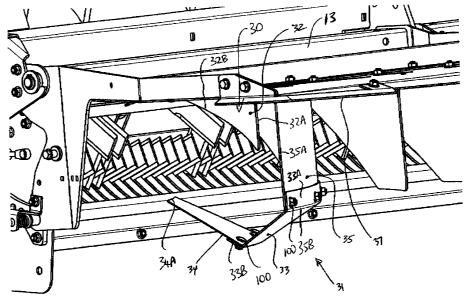
Thus referring to Figures 4 and 5, the outermost pair of fins indicated at 30
define a
first fin which is indicated at 32 and extends from a leading edge at or
adjacent the
front edge of the tailboard 13 to a trailing edge 32A rearward of the leading
edge but
forward of the rear edge of the tailboard. The fin includes an inclined lower
surface
32B so that the fin commences at zero height and gradually increases in height
to
the trailing edge 32A. In this way any crop material engaging the lower edge
32B
can slide off that edge as the crop material moves rearwardly in the
airstream.
The next adjacent fin is modified to include a second part generally
indicated at 31. This fin part 31 is made up of three sheets 33, 34 and 35
where the
first sheet 35 forms the main body of the fin and the sheets 33 and 34 form a
first
part and second part attached to the main body of the fin and defining a
generally
channel shaped portion best shown in Figure 4.
The sheet 35 as shown in Figure 5 has a top flange 35A at the top
edge for bolting to the underside of the tailboard at the guide surface
portion of the
tailboard using the mountings previously described. The sheet 35 when mounted
by
the flange 35A extends at right angles to the surface of the tailboard. The
sheet or
main body 35 of the fin extends from a leading edge 40 rearwardly of the
tailboard to
a trailing edge 35A located at the rear of the tailboard adjacent one side.
The sheet
CA 02578198 2011-08-15
18
35 has a bottom edge 35B which is parallel to the flange 35A and the top edge
of the
sheet 35. The leading edge 40 commences at a front end 40A and extends
rearwardly while increasing in height to a trailing end 40B of the leading
edge 40.
Again the inclined leading edge 40 commencing at zero height allows the crop
material to slide over this leading edge to be released from the fin should
any crop
material be trapped around that leading edge. Thus some of the crop slides
along
the sheet 35 along the concave side so as to be guided thereby in the
spreading
action.
At the bottom edge 35B of the sheet 35 is attached the second sheet
33. The sheet 33 has two mounting flanges at its side edges including a first
mounting flange 33A and a second mounting flange 33B. The mounting flange 33A
is arranged to lie along the outside surface of the sheet 35 at the lower edge
35B so
as to be bolted thereto by attachment bolts 100. The flange 33A is arranged at
an
angle to the main body of the sheet 33 so that the sheet 33 is inclined from
the lower
edge 35B in a direction downwardly from the lower edge and to the side of the
sheet
35 which is the concave side.
The angle of the sheet 33 to the sheet 35 is of the order of 120 but the
angle can vary between 900 and approximately 1500 .
The sheet 34 is attached to the flange 33B at the outer edge of the
sheet 33 by further bolts 100. The sheet 34 is arranged at an angle again of
the
order of 120 to the sheet 33. Thus the sheet 34 is inclined upwardly from the
lower
edge of the sheet 33 to an upper edge 34A of the sheet 34. As shown in Figure
5,
each of the sheets 33, 34 and 35 is curved in bottom plan view so that the
adjoining
CA 02578198 2011-08-15
19
edges at the side edges of the sheet 33 are also curved. The width of the
sheet 33
is substantially constant along its length so that the sheets 34 are
equidistantly
spaced along its length from the sheet 35. In cross section the sheets are
flat so as
to define a channel member with the sheet 33 at the base and the sheets 34 and
35
upstanding from that base and with the angle between the sheets of the order
of
120 as previously stated. The sheet 35 is directly attached to the underside
of the
tail board so as to extend at right angles to that surface. Thus the sheet 34
is
inclined toward the surface of the tail board. However the upper edge 34A of
the
sheet 34 is spaced downwardly from the surface of the tailboard so as to allow
any
crop material to enter the space therebetween to be channelled by the curved
fin
defined by these three sheets including the main body 35 and the two additions
sheets 33 and 34.
As previously stated the sheet 35 has a leading edge 40 extending
from the end 40A to the end 40B. The sheet 33 has a leading edge 330 extending
from an end 33D to a lower end 33E. Again the edge 330 is inclined rearwardly.
The sheet 33 thus has an outer edge 33F which is considerably shorter than the
inner edge 33G which is in turn considerably shorter than the edge 35E of the
sheet
35. Similarly the sheet 34 has a leading edge 346 which is inclined rearwardly
so
that the outer most edge 34A of the sheet 34 extends from an end 34C to a rear
end
34D and this is again shorter than the outer edge of the sheet 33 by a
considerable
distance. The sheet 34 also has a trailing edge 34E which is recessed from a
trailing edge 33H of the sheet 33. Thus the leading edge 34B and the trailing
edge
34E of the sheet 34 are tapered toward the outer edge 34A. However the sheet
34A
CA 02578198 2011-08-15
20
acts to confine air and flowing materials into the channel which is defined on
the
concave side of the sheet 35.
Referring again to Figure 5, the leading edge 40 of the sheet 35
terminates at the point 40B where it joins the outer edge of the sheet 35
which is
indicated at 35F. The leading edge 33C has its inner end 33D spaced rearwardly
from the end 40B of the leading edge 40. This forms a recessed portion 41
ensuring
that any crop material flowing over the leading 40 is released from the
leading edge
40 before it engages the leading edge 33C. This ensures that there is no
shoulder
or notch against which the crop material can engage to inhibit the free flow
of the
material over this edge. It will be appreciated that some crop material may
fold over
the leading edge in its movement rearwardly from the discharge opening onto
the
tailboard surface. It is necessary or highly desirable to ensure that the crop
material
is prevented from hanging up and hence the recess 41 at the junction between
the
outer edges of the sheet 35 and the sheet 33 and a similar recess 41 at the
junction
between the sheets 33 and the sheet 34 ensures that no such hang-up can occur.
Thus similarly the end 34F of the leading edge 34B of the sheet 34 is recessed
from
the end 33E from the leading edge 33C of the sheet 33 by the recess portion
indicated at 41.
Turning now to Figure 3, the tailboard is shown in top plan view
showing in phantom the outermost fin group 30 which includes the outermost fin
32
and the channel-shaped fin 31. These two fins are separate from one another
and
adjustably mounted on the tailboard. Each fin is mounted and pivots about a
front
mounting hole. Thus both fin 31 and 32 can be adjusted as previously described
so
CA 02578198 2011-08-15
21
that its forward end forms a pivot and its rearward end can be moved side to
side in
slots 16 (Figure 2). A link 36 visible in Figure 3 connects the fin 32 to the
next fin 31
so that these fins are adjustable in common movement. The link 36 however only
connects the outermost fin 32 to the next adjacent fin 31 and there is no
further
linkage to any of the remaining fins. The linkage 36 is merely a simple
connection
with no ability to effect adjustment of any of the fins except to control the
common
movement between the two fins 32 and 31.
A further modification to the tailboard comprises an extension portion
37 which is mounted on the tailboard at the corner between the side edge
indicated
at 13A and the rear edge indicated at 13B. The extension portion 37 is a plate
formed in a common plane with the bottom surface of the tailboard so that the
surface of the tailboard is extended outwardly beyond the rear edge 13B into
the
extension portion 37 and similarly the tailboard is extended beyond the side
edge
13A into the extension portion 37. The extension 37 is a plate that is made of
two
main planes. The side plane is 3 degrees sloping downwards to the side of the
tailboard, the rear surface is 3 degrees downwards from the rear tailboard
edge.
The purpose is to put a slight downward change to the trajectory of the
residue
stream after it has left the fin. This keeps the dust down and the residue
from
swirling up near the combine.
The extension portion 37 has a rear edge 37A and a side edge 37B.
The side edge 37B thus projects outwardly from the side edge 13A and the rear
edge 37A projects outwardly from the rear edge 13B with the rear edge 13B with
the
rear edge 13B extending across between the two extension portions 37 as best
CA 02578198 2011-08-15
22
shown in Figure 3. The side edge 37B is generally parallel to the side edge
37A and
symmetrically the rear edge 37A is parallel to the rear edge 13B. The
extension
portion extends only over a small part of the tailboard at the corner for co-
operation
with the channel shaped fin portion 31 underlying that extension portion 37.
Thus the outer two most fins 30 on each side of the tailboard
assemblies are configured to focus the high velocity air stream generated by
the fan
end rotor 26 on the chopped residue. The acceleration of the residue provides
a
wide spread under adverse side wind conditions. The outer two fins consist of
the
large fin 31 that carries and directs most of the residue and the smaller fin
32 that
alters the direction of the high velocity air to provide a tangential thrust
on the larger
fin and greater residue acceleration.
The outermost small fin 32 on the tailboard is used to redirect the
highest velocity air into a tangential vector with the rear end of next
adjacent or
second large fin 31. This provides the greatest acceleration of material and
the most
efficient use of the force available with the high velocity air. If the small
fin 32 was
removed the high velocity air would crash into fin 31 and bounce off of the
fin taking
material with it, most likely landing beside the chopper. The intention is to
slowly
turn the high velocity air and apply its energy to the residue. Surfaces 34
and 35 are
attached to fin 31 so that the air, that is reflected off of the residue when
being
accelerated, is held captive and can not bounce off in another direction. More
of the
energy in the air is used to accelerate the residue than without these
surfaces
present. Adding surface 34 has a huge impact on the retained air velocities.
In the
field, removal of the surface 34 reduces the spread width by 25% (10 feet).
CA 02578198 2011-08-15
23
The residue primarily travels on the vertical fin surface 35, however
conditions exist with tough, green straw where the residue discharged from the
chopper does not flow easily and will contact the other surfaces. Surfaces 33
and
34 serve to contain and focus the air on the residue stream. Outer surface 34
is
primarily used to contain the air that is being reflected from surfaces 35 and
33. The
small fin 32 is positioned to direct the high velocity air tangentially on to
the rear end
of fin surface 35 of large fin 31. The relative position of the two fins 31
and 32 is
maintained in an optimum tangential relationship with link 36. Adjustment of
the two
fins is available without the need to tune the relative fin positioning.
The large fin 31 is constructed so that plugging is minimized. In tough
field conditions heavy, wet residue is discharged down the leading edge 40 of
fin
surface 35. Each adjoining surface must start approximately W behind the
previous
surface, as indicated at 41. This enables any residue traveling down the
leading
edge to clear the next surface, and therefore avoids plugging situations. The
fin 32
has a passive leading edge since high velocity air must be able to pass by all
surfaces, keeping the tough sticky residue moving.
The tailboard extensions 37 are added to the outer ends of the
tailboard. The extensions serve to gradually change the direction of the high
velocity
residue stream while maintaining the momentum developed by the fins. It has
been
discovered that with the high velocity tailboard fin arrangement we are able
to
accelerate the residue to much greater levels and are therefore able to move
it much
more effectively against a stronger headwind. This also helps to keep the
dust,
CA 02578198 2011-08-15
24
generated when the flow stream slows and becomes turbulent, much further away
from the combine.
A number of alternate embodiments and potential improvements are
contemplated herein as follows:
Chaff spreaders ¨ the method to channel air velocity and keep it from
bouncing off of the accelerating residue.
The tailboard with the fin arrangement does not necessarily need to be
attached to a chopper housing it could be attached to the rear hood of the
combine
harvester with an internal chopper of the combine harvester providing the air
velocity.
A fan with a nozzle directed at the outer fins with the above mentioned
geometry
Since various modifications can be made in my invention as herein
above described, and many apparently widely different embodiments of same made
within the spirit and scope of the Claims without department from such spirit
and
scope, it is intended that all matter contained in the accompanying
specification shall
be interpreted as illustrative only and not in a limiting sense.