Note: Descriptions are shown in the official language in which they were submitted.
CA 02578427 2007-02-08
BELT TYPE CONVEYOR APPARATUS WITH
ADJUSTABLE TAIL PULLEY
This invention relates to conveyor apparatus and systems and,
in particular, a conveyor machine for use with a continuous conveyor
belt equipped with a tail pulley about which the belt can extend and
reverse direction.
Belt conveyors are well known and are efficient means for
moving large quantities of materials such as ore, coal and granular
stone over a predetermined distance extending either horizontally,
vertically or both. One form of conveyor system known for mining
applications is a system involving a series of conveyors mounted on
wheels so as to make the system easily movable. Because of the
manner in which mines are developed and extended, it may be
necessary for a relatively long conveyor system to be moved along a
substantially curved or zig zag course. Under such circumstances, it
can be difficult and time consuming to move the conveyor system
when required. It will also be appreciated that it may be necessary to
move the conveyor system and to make adjustments to the system
fairly frequently as the mining machine advances in a mine.
U.S. Patent No. 5,366,059 issued November 22, 1994 to Prairie
Machine & Parts Mfg. Ltd. describes and illustrates a conveyor system
comprising a plurality of conveyor vehicles connected together in the
form of a train and also describes a steering system for steering this
train of vehicles. All but one of the vehicles in the train has a single
pair of steerable wheels with the vehicle at the outby end of the train
(that is the end to which the mine material is being delivered) having
two steerable wheels. Hydraulic cylinders are used to steer each of the
pairs of steerable wheels and there is a control mechanism for
controlling and coordinating these cylinders in order to set the steering
angles of the pairs of wheels. In this known system, each pair of
wheels is mounted on an axle and each pair is driven by an electric
tram motor mounted along the longitudinal centre of the conveyor
vehicle. One difficulty encountered with this known conveyor system is
that the system is relatively high along most of the length of the train
CA 02578427 2007-02-08
2
and therefore the ceiling of the region of the mine where the mining
machine is operating must be reasonably high, for example over six
feet, to accommodate this conveyor system.
There is a need for a belt direction reversing tail pulley
mechanism which is mounted on a pulley support member that can be
pivoted about a generally vertically extending pivot axis and an
interconnecting support arrangement for this pulley support member
that includes a pivot connector for the pulley support member that
enables the latter to pivot about the aforementioned axis. By providing
a mechanism for pivoting the pulley support member about the pivot
axis, there can be provided a means to maintain the conveyor belt
within a desired central region of the tail pulley during use of the
conveyor. In particular, there is a need to provide a new tail pulley
mechanism and mounting therefor of the aforementioned type which
can be used in a conveyor apparatus having a low profile.
In addition, there is a need to provide an improved controller for
controlling an actuator capable of pivoting the pulley support member
about the pivot axis to maintain the conveyor belt within a desired
central region of the tail pulley. The aforementioned controller is
desirably an electronic controller such as a programmable logic
controller which is connected to light beam sensors which sense a shift
of the conveyor belt out of the desired central region and from which
the controller is able to determine when the belt requires recentering.
There is an additional need in a conveyor that uses an endless
conveyor belt to provide a support arrangement for mounting one of
the two pulleys of the conveyor wherein an actuator is provided for
pivoting a pulley support member on which the one pulley is rotatably
mounted to maintain the belt in substantially center running alignment
during use of the conveyor. In an exemplary embodiment, there is an
additional mechanism provided for adjusting the position of the
support arrangement relative to the support frame of the conveyor in
order to increase or decrease the overall tension in the conveyor belt.
One exemplary form of the aforementioned movable support
arrangement for a pulley is particularly suitable for a mobile conveyor
CA 02578427 2013-08-19
3
having a low profile, for example, less than five feet and preferably no
more than four feet.
According to one aspect of the invention, a conveyor apparatus
for use with a continuous flexible conveyor belt includes an elongate
conveyor support frame having opposite longitudinal sides extending
between two frame ends. A plurality of conveyor belt supporting
devices are mounted on and distributed along the support frame for
rotatably supporting the conveyor belt. These supporting devices
include a belt direction reversing tail pulley mechanism having two tail
pulley sections mounted on a pulley support member for rotation about
a common central axis of rotation extending generally transversely
relative to the longitudinal sides of the frame. The tail pulley sections
have adjacent inner ends and the pulley support member includes a
central support portion located at these inner ends and extending
radially outwardly from these inner ends relative to the axis of rotation
to a generally vertically extending pivot axis. The apparatus further
includes an interconnecting support mechanism for mounting the
pulley support member on the conveyor support frame, this
mechanism including a pivot connector connecting the central support
portion to the interconnecting support mechanism for pivotable
movement about the pivot axis. There is also provided a pivot
mechanism pivoting the pulley support member and the tail pulley
sections about the pivot axis to maintain the conveyor belt within a
desired central region of the tail pulley formed by the tail pulley
sections during use of the conveyor apparatus. The pivot mechanism
includes a belt control arm fixedly connected to the central support
portion for pivotal movement therewith and a hydraulic linear actuator
having an actuator rod pivotally connected to the control arm.
According to another aspect of the invention, a conveyor
apparatus for use with an endless, flexible conveyor belt for conveying
mine material includes an elongate conveyor support frame having
opposite longitudinal sides extending between two frame ends and a
plurality of conveyor belt supporting devices mounted on and
distributed along the support frame for rotatably supporting the
conveyor belt. These supporting devices include a belt direction
CA 02578427 2013-08-19
.= . ,
4
reversing tail pulley mechanism mounted on a pulley support member
for rotation about a central axis of rotation extending generally
transversely relative to the longitudinal sides. There is also provided a
support mechanism for mounting the pulley support member on the
conveyor support frame. The pulley support member is mounted on
the support mechanism for pivotal movement about a generally
vertically extending pivot axis provided by the support mechanism and
located centrally between the longitudinal sides of the support frame.
The support device includes two parallel link members pivotally
mounted on the conveyor support frame and having inner ends located
on or near a longitudinal centerline of the conveyor support frame and
a central mounting frame member pivotally connected to the inner
ends of the link members. The pulley support member is pivotally
connected to the central mounting frame member. An actuator is
provided in order to pivot the pulley support member and its tail pulley
mechanism about the pivot axis to maintain the conveyor belt within a
desired central region of the tail pulley mechanism during use of the
conveyor apparatus. An electronic controller is provided to control
operation of the actuator. There is also a sensor arrangement for
sensing a shift of the conveyor belt out of the desired central region
and for indicating this shift to the controller. The controller causes the
actuator to pivot the pulley support member in a direction which tends
to increase tension in the conveyor belt on the longitudinal side thereof
upon receipt of a signal from the sensor that the conveyor belt has
shifted out of the desired central region.
In an exemplary version of this conveyor apparatus, the sensor
arrangement includes two photoemitters and two photoreceivers with
each photoemitter and its aligned photoreceiver being located adjacent
a respective one of two outer end sections of the tail pulley
mechanism.
According to a further aspect of the invention, there is provided
a conveyor apparatus for use with an endless conveyor belt which
extends about two belt direction reversing pulley devices and is
operable under tension. This apparatus includes a conveyor support
frame and a non-rotating pulley support member on which one of the
CA 02578427.2013-08-19
two pulley devices is mounted for rotation about an axis of rotation.
There is further provided a movable support mechanism for mounting
the pulley support member on the conveyor support frame. The pulley
support member is mounted on the support mechanism for pivotable
5 movement about a substantially vertically extending pivot axis. An
actuator is provided for pivoting the pulley support member and its
pulley device about the pivot axis to maintain the conveyor belt in
substantially centered running alignment with the one pulley device
during use of the conveyor apparatus. Furthermore, there is a
mechanism for adjusting the position of a portion of the support
mechanism relative to the support frame in order to increase or
decrease the overall tension in the conveyor belt. This adjusting
mechanism is connected to the movable support device and capable of
moving the portion of the support device, the pulley support member
and its pulley device towards or away from the other pulley device to
decrease or increase the tension.
In an exemplary embodiment of the aforementioned conveyor
apparatus, the movable support mechanism includes two parallel,
spaced-apart link members pivotally mounted on the conveyor support
frame and having inner ends located near or at a longitudinal
centerline of the support frame which is elongate and substantially
rectangular in plan view. There is also a central mounting frame
member pivotally connected to the inner ends of the link members and
the pulley support member is pivotally connected to the central
mounting frame member.
These and other aspects of the disclosed conveyor apparatus
and adjustable tail pulley will become more readily apparent to those
having ordinary skill in the art from the following detail description
taken in conjunction with the accompanying drawings.
In the drawings,
Figure 1 is a top view of an exemplary embodiment of a
conveyor apparatus constructed in accordance with the invention;
Figure 2 is a side elevation of the conveyor apparatus of Figure
1;
CA 02578427 2013-08-19
,.
5a
Figure 3 is a bottom view of the conveyor apparatus of Figures 1
and 2;
Figure 4 is a sectional elevation taken along the line IV-IV of
Figure 2;
CA 02578427 2007-02-08
6
Figure 5 is a perspective view taken from above and from the
tail pulley end of the conveyor machine, this view showing an end
section of the machine including its two wheels;
Figure 6 is a sectional elevation taken along the line VI-VI of
Figure 1, this view showing details of the power steering arrangement
for each wheel;
Figure 7 is a detail top view of a left hand wheel unit assembly
of the vehicle of Figures 1 and 2, this view omitting the wheel itself for
sake of illustration;
Figure 8 is a detail sectional elevation taken along the line VIII-
VIII of Figure 7;
Figure 9 is a detail end view of the wheel unit assembly of Figure
7, this view being taken from the left side of Figure 7 and showing the
wheel mounted on the assembly;
Figure 10 is a detail sectional elevation taken along the line X-X
of Figure 9;
Figure 11 is a perspective detail view of a mounting plate
weldment used to support each wheel and its hydraulic motor;
Figure 12 is a detail perspective view illustrating a pivotable
motor support member mounted adjacent each wheel;
Figure 13 is a partial bottom view of the conveyor machine
showing the end where the tail pulley is mounted;
Figure 14 is a detail view of the circled area marked E in Figure
1;
Figure 15 is another detail view taken along the line XV-XV of
Figure 14;
Figure 16 is a bottom view showing a portion of the curved track
and the hitch unit mounted for rolling movement on the track;
Figure 17 is a vertical cross-sectional detail taken along the line
XVIi-XViI of Figure 16;
Figure 18 is a vertical cross-section taken along the line XVIII-
XVIII of Figure 16 illustrating how the rollers engage the track;
Figure 19 is a detail view showing the transverse cross-section
of the curved track according to an exemplary embodiment;
CA 02578427 2007-02-08
7
Figure 20 is a top view of a roller mounting support body which
is part of the hitch unit;
Figure 21 is a vertical cross-section of the roller mounting
support body taken along the line XXI-XXI of Figure 20;
Figure 22 is a perspective view of the roller mounting support
body of Figure 20 taken from above and from its pivot pin end;
Figure 23 is perspective view of a pivoting hitch frame which is
pivotably connected to the support body of Figure 20, this hitch frame
being shown from above and from an inner side thereof;
Figure 24 is a perspective view of an intercar angle sensor
assembly mountable on the hitching apparatus;
Figure 25 is an axial cross-section of the sensor assembly of
Figure 24;
Figure 26 is a perspective view taken from above and from the
inby end showing the tail pulley mechanism and an interconnecting
support mechanism for mounting the tail pulley;
Figure 27 is a vertical cross-section of the tail pulley mechanism
and the interconnecting support mechanism taken along the line
XXVII-XXVII of Figure 29;
Figure 28 is a perspective view of a tail pulley take-up member,
a component of the interconnecting support mechanism;
Figure 29 is a plan view of the tail pulley mechanism and the
interconnecting support mechanism of Figure 26;
Figure 30 is a vertical cross-section of the tail pulley mechanism
including a pulley support member, this view taken along the line XXX-
XXX of Figure 29;
Figure 31 is a perspective view of the pulley support member
and a belt control arm connected thereto;
Figure 32 is a partial top view of the pulley support member and
belt control arm of Figure 31, the right section of the shaft being
omitted as it is constructed in the same manner as the illustrated left
section;
Figure 33 is a top view of the tail pulley take-up member of
Figure 28;
CA 02578427 2007-02-08
8
Figure 34a to 34e are a series of diagrams illustrating the PLC
program file for controlling the conveyor and belt training system;
Figure 35 is a schematic illustration of a network of
programmable logic controllers for a train of mobile conveyors; and
Figure 36 is an electrical circuit diagram illustrating the circuits
connected to the PLC to operate the conveyor belt and the belt training
system.
A conveyor apparatus constructed in accordance with the
invention is illustrated in Figures 1 to 5 of the drawings. The
illustrated, low profile conveyor vehicle 10 has been shown without the
usual flexible conveyor belt, the location of which is only indicated in
chain-link lines in Figure 1 for sake of illustration. This conveyor belt
12 is an endless conveyor belt and can be of standard construction
depending upon the type of material being conveyed by the conveyor
system. The illustrated exemplary conveyor apparatus is a vehicle
intended for use as an intermediate conveyor car of which there may
be five, ten or more in a train of conveyor vehicles similar to the train
illustrated and described in U.S. Patent No. 5,366,059. It will be
understood that in addition to a plurality of intermediate conveyor
vehicles pivotably connected end-to-end, there can also be a loading
conveyor vehicle which is located at the end of the train adjacent the
mining machine, and a discharge conveyor vehicle located at the
opposite end of the train which is referred to as the outby end, that is,
the end to which the train of vehicles delivers the material. The loading
car assembly can be constructed in a similar manner to the illustrated
intermediate car assembly 10, except that it need not be provided with
a hitch mechanism at its inby or hopper end, since there is no need to
attach this end to another conveyor vehicle. As for the discharge
conveyor vehicle, it is provided with two pairs of transversely aligned
wheel units rather than a single pair of these wheel units described
hereinafter. However, the wheel units on the discharge car can be
constructed in the same manner as described hereinafter, including
their steering mechanism and their hydraulic drive mechanism. The
discharge car is also provided with a pivotable cross-conveyor for
discharging the material onto a permanent or fixed conveyor in the
CA 02578427 2007-02-08
9
mine. A cross-conveyor and its use is described and illustrated in U.S.
Patent No. 5,366,059. A detailed description of the discharge car and
its cross-conveyor herein is deemed unnecessary as a cross-conveyor
system is not considered an aspect of the invention claimed herein.
Turning now to the illustrated conveyor apparatus 10, this
apparatus has a conveyor mechanism 14 that includes an elongate,
substantially horizontal frame 16 and a plurality of conveyor belt
supporting devices which as illustrated include spaced apart conveyor
roller devices 18 mounted on the horizontal frame 16 and adapted to
support rotatably an upper run of the continuous conveyor belt 12
extending between opposite end sections of the vehicle. The roller
devices 18 can be of standard construction available from conveyor
parts suppliers. Each illustrated roller device comprises three metal
rollers 20 which are pivotably connected together in an end-to-end
fashion by their central shafts. The outer end of each outer roller is
connected by a chain 22 (see Figure 5) to a vertical support post 24
mounted on a main, longitudinally extending frame member of the
main frame 16. The height of each pair of posts 24 varies as shown to
gradually increase the height of the roller devices. In addition to the
The belt supporting devices include a belt direction reversing tail
pulley mechanism mounted adjacent one end of the conveyor
mechanism on the horizontal frame 16 and having a rotatable tail
pulley indicated at 32. Further details of the construction of the tail
pulley unit are provided hereinafter with reference to Figures 5, 13 to
CA 02578427 2007-02-08
also an electric motor mechanism 38 which can be considered part of
the head pulley unit since it rotates the head pulley 36 to move the
conveyor belt and thus to transport material from the tail pulley to the
head pulley. A belt scraper 40 of known construction can be mounted
5 adjacent to the head pulley to help keep the conveying surface of the
belt clean. Mounted adjacent to the head pulley at the outby end of the
vehicle is a material hopper 42 which helps direct the material onto the
conveyor belt of the next conveyor vehicle of the train. There can be
provided a pivoting hitch mechanism 44 at the inby end of the vehicle.
10 This hitch mechanism can include a curved steel track and a rolling
hitch device 48 having two sets of grooved rollers located at 50 and 52
on two opposite V-shaped sides of the track 46. Two car hitch pins 54
are located on opposite sides of the hitch device 48 which is able to
pivot about a central longitudinal axis of the vehicle by mean of central
pivot pin 56 (see Figure 18). Located near the opposite head pulley
end of the car are two hitch pin holders 60, one on each side of the
frame 16.
The conveyor vehicle 10 has a pair of transversely aligned wheel
units indicated generally at 62 for supporting and moving the conveyor
vehicle. Each of these wheel units is separately connected to the
horizontal frame 16. In particular, each wheel unit is connected to a
respective longitudinally extending side of the frame. Each wheel unit
has its own solid wheel with the wheel on the left side indicated at 64
and the wheel on the right hand side indicated at 66. As explained
more fully hereinafter, each wheel 64, 66 is mounted for pivotable
movement about a substantially vertical pivot axis for steering
purposes, that is, to steer the vehicle 10. In an exemplary embodiment
of the conveyor vehicle, each wheel unit includes a standard hydraulic
motor 68 shown clearly in Figure 8. This motor is used to rotate or
drive the wheel of the respective wheel unit. Also, each wheel unit
includes a non-rotating wheel support structure indicated generally at
70 for detachably connecting the wheel unit to the horizontal frame.
The left hand wheel unit 62, with its wheel removed, is illustrated in
Figure 7 and is illustrated with its wheel in Figures 8 and 9. Figure 7
also shows a power steering mechanism or power steering means 72
CA 02578427 2007-02-08
11
for steering the wheel of this wheel unit. The illustrated power steering
mechanism includes a hydraulic linear actuator having a hydraulic
cylinder 74 and an actuator rod 76 slidable in the cylinder. A steering
arm 77 having a L-shape is rigidly attached at one end to an upper
section of a motor support member 144 (see Figure 12) and is
pivotably connected at its other end to the rod 76 by means of a bolt
and nut 80 (see Figure 9). The closed end of cylinder 74 is pivotably
mounted by means of lugs 82 to an end of a horizontally extending,
elongate arm section 84 which is part of a wheel unit mounting plate
86. A nut and bolt combination 88 pivotably connects a short
connecting plate 90 that is rigidly attached to the end of the cylinder to
the lugs 82. The actuator rod 76 can be provided with a spherical
bearing 92 that is connected by threads to the outer end of the rod.
This bearing is connected to the steering arm 77 by the nut and bolt
80.
In addition to the arm section 84, the flat mounting plate 86
includes a main plate portion 96 shown in Figure 6. This main plate
portion has a generally rectangular shape except for cut-off bottom
corners 98. The arm section 84 extends horizontally from an upper
corner of the main plate portion 96. An advantage provided by the arm
section 84 is that the hydraulic cylinder can then be pivotably mounted
to the same mounting plate 86 as the wheel and its hydraulic motor
68. As can be seen from Figures 6 and 11, each wheel unit 62 and, in
particular its mounting plate 86 (which is part of the wheel support
structure), is formed with a plurality of apertures or holes indicated
generally by reference 100 which are provided to receive fasteners,
preferably bolts, used to attach the respective wheel unit to the frame
16. A plurality of fasteners 102 for this purpose are insertable through
spaced-apart apertures 104, four of which can be seen in Figure 6.
There are a plurality of the apertures 104 formed in each longitudinally
extending side of the frame 16 and optionally additional apertures can
be provided in extension plates attachable to the main frame
members. The apertures 100 formed in the mounting plate 86 are
located in opposite end sections of the mounting plate as clearly shown
in Figure 11. The illustrated aperture arrangement permits the height
CA 02578427 2007-02-08
12
of each wheel unit relative to the horizontal frame 16 to be adjusted
between either one of two possible positions, but it will be appreciated
by those skilled in the art that by providing further apertures 104, for
example, on each longitudinal frame member or an extension plate, it
is possible to provide for more than two possible height positions for
each wheel unit. In the position of the wheel unit illustrated in Figure
6, the wheel unit 62 is at its maximum height relative to the frame 16.
In this position, the overall height of the conveyor vehicle will be a
minimum height which, in an exemplary embodiment, is only four feet
or forty-eight inches as compared to earlier conveyor vehicles such as
those described and illustrated in U.S. Patent No. 5,366,059 which had
an overall height of six feet or seventy-two inches. In this position of
the wheel units in the exemplary embodiment, the ground clearance
provided under the vehicle is six inches.
Turning now to the wheel support structure 70, shown in Figures
8 and 11, the wheel support structure includes upper and lower,
horizontally extending wheel supporting arms 120, 122, both with
rounded distal ends. The upper arm 120 can be formed from a single
steel plate welded to the top of mounting plate 86 and is formed with a
round hole 122 to receive an upper pivot pin member. As illustrated,
the lower support arm 122 can be constructed of two short plate
members 124, 126 which are welded together at 128 and which extend
at an obtuse angle to one another as shown in Figure 8. The strength
and rigidity of the connection between the sloping plate 124 and plate
86 can be strengthened by two vertically extending gussets 130 which
are welded to these plates. A top pivot pin 132 is mounted in the hole
122 and is connected to the upper arm 120 by six screws 134. The
pivot pin can be provided with a central passageway (not shown) that
extends downwardly from grease zerk 136. There is also a bottom
pivot pin 138 having a reduced top end extending into a circular recess
140 formed in the rounded end section of the lower support arm 122.
In order to pivotably support the wheel and its hydraulic motor
68, there is provided a substantially annular motor support member
144 shown in Figure 12. This support member has a circular recess
146 formed on its top side and into this recess a reduced bottom end
CA 02578427 2007-02-08
13
section of the top pivot pin 132 extends. Mounted in this recess is a
spherical angular contact bearing 148 which, in one embodiment, has a
bore measuring 13/4" and has an outside diameter of 2 13/16 inch.
Protecting this bearing and extending around the top edge of the
bearing is a suitable seal such as a Chesterton Super Wiper seal 150.
Similarly, extending around a reduced upper portion of the bottom
pivot pin is a spherical angular contact bearing 152 which is sealed by
means of a Chesterton super wiper seal 154. The bottom pivot pin can
be greased through grease zerk 156.
Returning to Figure 12, it will be seen that the motor support
member 144 has a bottom extension 160 which is welded to the
annular portion of the support member 144 and which has a circular
hole 162. The bottom pivot pin projects through the hole 162 from the
bottom and is detachably connected to the extension 160 by six screws
164 which extend through a flange extending around the bottom of
this pivot pin. Formed between the extension 160 and the annular
portion of support member 144 is a cavity 166 which receives the
rounded end portion of the horizontal plate 126. In this way, the
support member 144 is pivotably supported from below.
It can also be seen from Figure 12 that the support member 144
has a radially inwardly extending connecting flange 170, this flange
being formed with a series of fastener holes 172. As shown in Figure
10, six screws 174 can be used to attach the hydraulic motor 68 to the
flange 170 along with its associated planetary gear box 176. The
planetary gear box has an annular rotating flange 178 which is
attached by nine hex nuts 180 to a circular plate 182 forming a central
portion of the hub of the wheel. The nuts are threaded onto studs 184
visible in Figure 7, these studs extending through the rotating flange
on the gear box. It is understood that the left and right wheels 64, 66
are solid rubber wheels and, in one embodiment, each wheel measures
10" x 24" in diameter. The left and right wheels 64, 66 are connected
by a steering tie rod 190 shown in Figure 4 which ensures that the
wheels pivot in the same way at the same time. It is connected at each
end to the tie rod arm 78 of the respective wheel by means of a bolt
with a nylon insert lock nut 192.
CA 02578427 2007-02-08
14
It will be understood that the hydraulic motor for each wheel
unit is provided with pressurized hydraulic fluid through hydraulic lines
and fittings of standard construction which are readily available and
well known in the art. Most of these lines are not shown for ease of
illustration. Some of these lines are indicated at 194 in Figure 10.
Connecting fittings for these lines can be supported by a small bracket
196 shown in Figure 12. It will be understood that the hydraulic motor
itself and its gear box are of standard construction and accordingly a
detailed description herein is deemed unnecessary.
= 10 Various other features in the illustrated exemplary low
profile
conveyor vehicle that are shown in Figures 1 to 3 include a plastic
energy chain 200 through which electrical cables and wires are fed for
the operation of the vehicle and an energy chain guide 202 which helps
to support the movement of the energy chain. Mounted to the frame
on the left side is an electrical power box 204 of standard construction,
this box having an access door 206. Mounted to the same side of the
frame is an electric motor 208 which powers first and second hydraulic
pumps 210 and 212, the first pump 210 being used to drive the
hydraulic motors for the wheels and the second motor 212 being used
to power other hydraulic components on the vehicle. Two standard
filters for the hydraulic system are provided at 214 on the right side of
the vehicle. Mounted above these filters is a junction box 116. A third
hydraulic filter can be provided at 218 adjacent the pump 212. On or
between the two longitudinal main frames of the frame 16 and
adjacent one of the cross-frames 220 is a hydraulic fluid reservoir 222.
Another junction box for electrical components including connectors is
provided on the right side at 224. The side mounted electrical motor
38 for the head pulley is connected to a conveyor gear box 226 which
has an output shaft connected to the shaft of the head pulley. In one
embodiment, the motor 38 is a 7.5 kwatt or 10hp motor Also on the
right side of the vehicle there is mounted to the longitudinal frame
member a hydraulic assembly manifold 230 which is protected by a
shroud or guard 232. On the other side of the frame near the motor 38
is a control box containing a programmable logic controller for
controlling the operation and steering of the vehicle, the box indicated
CA 02578427 2007-02-08
at 234. In a known manner, the vehicle 10 can also be provided with
water sprayers, two of which are indicated at 240, 242. Water hoses
(not shown) are connected to the sprayers to reduce dust levels
generated by the conveyor system.
5 Figures 13 and 16 illustrate the pivot mechanism or pivoting
hitch mechanism 44 for pivotably connecting the mobile conveyor
machine of Figures 1 and 2 at its inby end (also sometimes referred to
herein as its first end) to an adjacent end section of another mobile
conveyor machine which can be constructed in the same manner as
10 the machine or vehicle of Figures 1 and 2. As indicated above, this
pivot mechanism includes the curved track 46 which can be of uniform
transverse cross-section and, in an exemplary version, has the cross-
section illustrated in Figure 14. The curved track is bent in a horizontal
circular arc as clearly shown in Figure 5, for example, and this arc has
15 a center of curvature located midway between the propelling devices,
that is the wheels 64, 66. This center of curvature is indicated at C in
Figures 3 and 4. The center of curvature is on a common axis of
rotation for the two wheels when these two wheels are positioned to
move the conveyor mechanism in a straightforwards direction. This
axis of rotation is indicated at A in Figure 3. The track is rigidly
mounted on the supporting frame 16 which includes a curved bumper
frame 350 having a rectangular transverse cross-section, this frame
extending the length of the track. The track, which is preferably made
of machined solid steel, can be welded to the bumper frame. Each end
of the track can be fitted with a rectangular stop plate 352 secured in
place by screws threaded into holes formed in each end of the track.
An exemplary form of the track has a cross-section such as that shown
in Figure 19 The track has two opposite roller engaging sides 354, 356,
with the side 354 being on the inner side of the track and forming a
concave curve and the side 356 being on the outer side and forming a
convex curve. Each of these sides in the exemplary illustrated version
engages three rollers with one of the rollers engaging the side 356
being shown in cross-section at 358 in Figure 18 Another roller 360 is
shown in part in Figure 18and this is one of the three rollers engaging
the side 354. The three rollers engaging the side 356 form a first set of
CA 02578427 2007-02-08
16
rollers and the three rollers engaging the side 354 form a second set of
rollers. It will be seen that the track 46 is captured and held between
the first and second set of rollers. The rollers of both sets have V-
grooves 362 formed about their circumferences. The use of three
rollers in each set helps keep the hitch unit correctly oriented on the
track at all times.
Turning now to the exemplary cross-section illustrated in Figure
19, the outer convex side 356 which faces towards an adjacent end of
the mobile conveyor machine has an upper sloping surface 364 which
extends at a 45 angle to the vertical centerline Z of the track. The
outer surface also has a lower sloping surface 366 which extends at a
45 angle to the axis Z and there can be a short vertical surface
provided at 368. The inner roller engaging side 354 is similarly shaped
with 45 sloping surfaces at 370 and 372. These surfaces can be
formed by a standard machining process. Also formed in the track
member is a rectangular groove 372 which can extend the length of
the track member on the side 356. The purpose of this groove is to
accommodate a length of roller chain 374 used in conjunction with an
angle sensor described hereinafter.
Turning now to the construction of a roller mounting support
body 376 illustrated in Figures 20 to 22, this body is used to rotatably
support the aforementioned two sets of rollers which engage the track
46. This body includes a horizonally extending support plate 378 which
can have a generally trapezoidal shape and is formed with six circular
holes 380 which accommodate upwardly extending shafts 381 of the
rollers. If desired, a shallow circular recess 382 can be formed around
each hole to partially accommodate a nut 382 which is threaded onto
the roller shaft by suitable threads (not illustrated). Each roller unit is
a standard roller and therefore has not been shown in detail. The short
shaft 380 extends into and supports the roller. The support body also
has a vertical pivot pin support plate 384 which is fixedly connected to
an edge of the roller support plate 378. The two plates can be welded
together at 386. The horizontally extending, central pivot pin 56 is
mounted in a circular hole formed centrally in the support plate 384.
The pin 56 is formed with a circumferential flange 388 near its inner
CA 02578427 2007-02-08
17
end, this flange resting against the support plate 384. The inner end of
the pivot pin can be welded to the plate 384. To strengthen the
support body 376 two rectangular side plates can be welded thereto at
390, 392. A support plate 394 can be welded to the top edge of the
plate 384 and is shaped to form an obtuse angle. Four fastener holes
396 can be formed in the outer end of this support plate. The arm 394
is used to detachably connect one end of the aforementioned energy
chain 200. If desired, a cover plate 395 (see Figure 3) can be attached
to the bottom of the support body 376 by means of screws 400
inserted through the cover plate and threaded into holes 402. It will be
understood that each roller is provided with internal bearings of
standard construction.
Turning now to the construction of the pivoting hitch mechanism
or hitch frame 44 illustrated separately in Figure 23, this frame is
pivotably connected to the support body 376 by means of the pivot pin
56. The pivot pin extends into a pin passageway which is formed in a
transverse center of the frame. It will be understood that the
passageway 404 which has a circular cross-section extends in a radial
direction relative to the radius of the track 46. The hitch frame includes
a central block 406 in which the passageway is formed, two tubular
arm sections 408, 410 and two end sections 412, 414 located on
opposite sides of the pivot pin and spaced therefrom, these end
sections being adapted for a pivot connection to an adjacent end
section of a second or another mobile machine (similar to or the same
as the illustrated machine of Figures 1 and 2) during use of the hitch
apparatus. Each arm section 408, 410 can be formed from a horizontal
top plate 416, a similar, horizontal bottom plate 418, an inner
rectangular plate 420 and a rectangular, vertical outer plate 422 (see
Figure 5). These plates can be made of 3/4 inch steel plate and can be
rigidly connected by welding. Each end section 412, 414 can be formed
from a bent steel plate forming an obtuse angle as shown in Figure 23.
The plate used can be one inch steel plate and its connection to its arm
section can be strengthened by a triangular brace or gusset 424. A
circular hole 426 is formed in the rounded end of each end section to
receive a respective one of the car hitch pins 56 shown in Figures 1, 2
CA 02578427 2007-02-08
18
and 5. Thus, the hitch apparatus of this invention can be pivotably
connected to an adjacent second mobile machine by means of these
hitch pins which permit relative pivotable movement about a horizontal
axis between the two mobile machines or mobile conveyors.
As shown in Figure 18, a grease passageway 430 can be formed
in the top of the block 406 and a grease fitting or grease zerk is
mounted in the block at the outer end of this passageway. Extending
around the pivot pin are fiberglass bushings 432 with one located
adjacent the flange 388 and the other located adjacent the outer end
of pin passageway 404. Also, a fiberglass thrust bearing 434 can be
sandwiched between the inner end of the block 406 in a shallow,
circular recess 436 and the flange 388. Hitch mechanism 44 is retained
on the central pivot pin 56 by means of an annular retainer plate 436
which can be 718th inch plate having a central hole measuring 1 13/16th
inch. Both the plate 436 and the pivot pin are formed with aligned
holes to receive a dowel pin 438 which acts to prevent rotation of the
plate relative to the pin. The plate 436 is held in place by 3 1/2 inch long
screw 440 which extends into a threaded hole formed in the center of
the pivot pin. It will thus be seen that the hitch mechanism 44 is free
to pivot about the horizontal pivot axis formed by the pivot pin thereby
allowing relative movement about this pivot axis between the adjacent
connected mobile conveyor vehicles.
For use with an automatic steering system for a train of these
mobile conveyor machines of the type described above, it can be
desirable for the steering system to know the intercar angle between
adjacent cars in the train. Due to the fact that the present mobile
conveyor machine has no pivot joint located at the pivot axis between
adjacent cars (in other words, there is only a virtual pivot point
midway between the two wheels of the machine described herein), a
special intercar angle sensor can be provided in conjunction with the
pivot mechanism of the present invention so that an electrical signal
indicative of the intercar angle can be provided to the steering control
for the conveyor train. An exemplary form of such a sensor is
illustrated in Figures 24 and 25. This sensor indicated generally by
reference 450 is able to determine the angle between the central
CA 02578427 2007-02-08
19
longitudinal axis of the illustrated mobile conveyor machine 10 and a
central longitudinal axis of another mobile conveyor machine which can
be constructed in the same or a similar manner as the illustrated
machine. Although not shown in Figure 24, the sensor includes the
aforementioned tensioned roller chain 374 mounted on the track 46. It
will be appreciated that this chain forms a series of sprocket engaging
recesses formed along one side of the track for at least most of the
length of the track. The other major component of the sensor is a
rotational position transducer 452 which is mounted on the hitch
mechanism 44 and, in particular, on the roller support body 376. The
sensor has a sensing sprocket 454 which drives an encoder to measure
the intercar angle. The transducer 452 can, in one embodiment, send a
signal to a Siemens programmable logic controller (PLC) used to steer
the train of vehicles. This transducer, which can be of standard
construction, can have a signal output ranging between 4 - 20
milliamps with the output depending upon the sensed intercar angle.
With reference to Figures 24 and 25, in addition to the
transducer, there is shown a mounting arm 456 which includes an
annular end section 458 on which the transducer can be mounted. The
arm 456 is attached by a pivot pin 457 to the bottom edge of the side
plate 392, this pivot pin extending through hole 458. There can be
mounted in this hole two Oilite friction bearings 460, one at each end.
Rotatably mounting the shaft for the sprocket 454 are two deep groove
ball bearings 462 arranged next to one another. The bearings can be
held in an opening by means of a retaining ring 464. On the transducer
side of the bearings there can be a further external retaining ring 466.
Welded to the arm on the side opposite the sprocket is a transducer
mount 468 which extends through an arc of more than 270 . Attached
to this mount by four screws 470 is a transducer mounting plate 472.
The central shaft of the transducer extends through this plate and is
received within a central passageway formed in sprocket shaft 474 and
is secured thereto (for example by a set screw) for rotation therewith.
The transducer is detachably mounted to the plate 472 by four screws
476. The end of an electrical control cable operatively connected to the
transducer is indicated at 478.
CA 02578427 2007-02-08
It will be seen from the above description that the transducer
and its mounting are pivotably mounted to the plate 392 of the hitch
mechanism. An elongate coil spring 480 (see Figure 16) is then
provided to bias the sensor and in particular its sprocket 454 into
5 engagement with the roller chain 374. The reason for this spring
mounting is to provide some flexibility to the sensor mount, thereby
reducing the possibility of damage, for example, if something such as
dirt or a stone should become lodged in the sprocket or the roller
chain. It should also be noted that the roller chain is kept under
10 tension itself by means of an adjustable tension rod 482 at one or both
ends of the chain.
Turning now to the mounting mechanism which includes
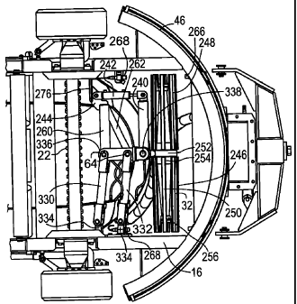
interconnecting support means for the tail pulley 32, this mounting
mechanism as seen most clearly in Figures 13, 26 and 29 includes two
15 parallel link members 330 and 332 which are pivotably mounted on
link mounts 334 mounted on the inside of the frame 16 by a
connecting plate 336. The inner ends of the link members are located
near or at the longitudinal centreline of the car and are pivotably
connected to central mounting frame member 336 which provides
20 support for a generally vertically extending pivot connector in the form
of pin 338. Pivotably connected to this pin connector is a belt control
arm 240 which in turn is pivotably connected to the actuator rod of a
belt training actuator which includes hydraulic cylinder 242. The closed
end of this cylinder is pivotably connected to a horizontal support plate
244.
The tail pulley itself comprises two rotatable tail pulley sections
246 and 248 which rotate about a non-rotating central support shaft
250 that extends from opposite sides of a central support portion in
the form of a circular support block 252 rigidly connected to one end of
the control arm 240. Mounted on opposite sides of the central support
portion are two central bearings 512, each rotatably supporting a
respective one of the pulley sections 246, 248. In a known manner,
the exterior of these pulley sections comprises a series of parallel,
spaced-apart metal slats, the inner ends of which are mounted on an
annular support block 502. An outer bearing 516 is also mounted on
CA 02578427 2007-02-08
21
the outer end of each section of the shaft 50 to support the outer end
of the respective pulley section. Further support for the tail pulley in
the longitudinal direction is provided by horizontally extending frame
members 260, 262 which are fixedly connected to the central frame
336 and are also connected to the plate 244.
Details of the construction of the tail pulley mechanism including
its two tail pulley sections 246, 248 and the pulley support member on
which these pulley sections are mounted for rotation are shown in
Figures 27, 29 and 30. Each tail pulley section includes an elongate
pipe 500 having an annular support block 502 welded to its inner end
and a smaller annular support block 504 welded to its outer end.
Extending lengthwise along the pipe and distributed about its
circumference are a series of slat supporting plates 506 and mounted
on the outer edge of each of these plates is a steel strip or slat 508.
Extending between and connecting the plates 506 are a series of
tapered, connecting plates 510. Roller bearings 512 are mounted
within the larger support block 502. In one embodiment these are
Timkin tapered roller bearings, Part No. 29586 Cone/29520 Cup.
Mounted adjacent these bearings is a suitable seal, for example, a CR
seal, type CRWHAl, Part No. 30095. Similarly, the aforementioned
outer bearings 516 are mounted in the outer support block 504. In one
embodiment, these are Timkin tapered roller bearings, Part No.
LM104949 Cone/LM104911 Cup. Holding these bearings in place is a
bearing lock nut 518 and a nut washer. Covering the lock nut is an end
cap 519 having a circumferential connecting flange. This flange is
connected by screws 521 to the support block 504.
Turning now to the construction of the pulley support member
indicated generally at 520 in Figures 31 and 32, this member includes
the aforementioned support shaft which is divided into two similar
outer sections and a central support portion 522. In the illustrated
embodiment, the shaft is formed from two mild steel members
including elongate shaft member 524 and an annular central member
526 through which the shaft member 524 extends. The central
member 526 is secured to the member 524 by heating the member
526 to a temperature in the range of 350 to 400 F., placing it
CA 02578427 2007-02-08
22
centrally on a thicker, central portion of the member 524 and then
slowly cooling the member 526. The shaft member 524 can have
tapered portions at 528 and 530. Each outer end of the shaft member
524 is threaded at 532 in order to attach the aforementioned lock nut
518. A key seat 534 can be provided for a key to hold the lock nut in
place.
Attached to one side of the central support portion 522 is a short
connecting block 536 made from steel plates and connected to pivot
pin sleeve 538. Rigidly attached to one side of this sleeve (such as by
welding) is the control arm 240 which can be tubular with a square
cross-section. As shown, this arm 240 extends parallel to the adjacent
section of shaft member 524. Connected to the top of the control arm
240 is a connecting plate 540 which is attached by a suitable pivot pin
extending through hole 542 to the actuator rod of the hydraulic
cylinder 242.
The exemplary link members 330, 332 as shown are of identical
construction and are best seen in Figure 26. Each link member or
swing arm comprises a rectangular hollow arm member 550 which
includes an elongate top plate 552, a similar bottom plate, and two
flat, rectangular side plates 554. There are also two rectangular end
plates (not shown) which extend between the top and bottom plates
and between the two side plates. Mounted to the top plate 552 are two
connector plates 556, each of which has a circular hole at one end to
accommodate a pivot pin. A rectangular bump 558 can be provided
adjacent each of the holes in order to engage a flat side on the head of
the respective, adjacent pivot pin 560. It will be appreciated that there
are two pivot pins at the inner ends of the swing arms and two pivot
pins at the outer ends of the swing arms. Mounted on both sides of
each swing arm is an optional grease line coupler 562. The lines
attached to each coupler can provide grease to a respective pivot pin
560, 338. In one embodiment, each pivot pin 560 is a 1 1/4 inch pin
having a length of 8 1/16 inch, including its enlarged head. The bottom
end of each pin can be formed with an annular recess to accommodate
a ring retainer.
CA 02578427 2007-02-08
23
With respect to the illustrated construction of the central
mounting frame member 336, this member includes a flat top plate
564 and a similar bottom plate 566 and extending between these two
plates and connecting same is a vertical plate 568. Located at opposite
ends of the plate 568 are two, similar cylindrical sleeves 570 and 572,
each of which can be provided with a short passageway at its center
for introduction of grease by means of a grease zerk or the
aforementioned grease line connected thereto. A pivot pin bracket 574
is welded to the side of the sleeve 572 and includes rectangular
connecting plate 576 and two lugs or ears 578, 582, each having a '
hole to accommodate the pivot pin 338. The lug 578 can be formed
with a shallow recess at 584 to accommodate the head of the pivot pin
and this recess can be flat on one side to accommodate a flat side of
the head of the pivot pin, thereby preventing rotation of the pivot pin
in the lug openings. It should be noted here that although the pin 338
forms the pivot axis which extends generally vertically, in the
exemplary embodiment shown, this pivot axis extends at a small acute
angle to vertical, this angle corresponding approximately to the angle
of inclination of the conveyor belt that extends around the tail pulley
sections. In one embodiment of the conveyor vehicle, this angle of
inclination is less than 10 . As used herein in connection with the pivot
axis formed by the pin 338, the expression "generally vertically
extending" or equivalent description includes not only a vertical pivot
axis but also one extending vertically but at an acute angle to a
vertical axis. The frame member 260, which can be tubular in its
construction with a square transverse cross-section can be welded to
the side of the sleeve 570, extending at a 90 angle to the plate 568.
The frame member 262 can also be tubular in its construction with a
square transverse cross-section. This frame member is welded to the
side of the sleeve 572 and to an end section of the frame member 260.
The interconnecting support mechanism for the pulley support
member includes the aforementioned link mounts 334. As shown,
these include two cylindrical sleeves 586, 588, each of which is welded
to a mounting block 590, 592. The base of each of these blocks is
welded to the connecting plate 331 which has a number of bolt
CA 02578427 2007-02-08
24
receiving holes 594. In one embodiment there are eight holes 594
distributed over the plate with each hole measuring 25/32 inch. Each
mounting block and its respective sleeve is mounted at a small acute
angle to vertical, this angle corresponding to the desired angle of the
pivot pin 338 relative to vertical.
The mounting block 592 can be made bigger than the block 590
in order to accommodate a horizontal hole formed therein to receive
the photoreceiver 268 which is part of the photosensor system
explained below.
The position of the tail pulley can be adjusted for belt training
purposes either manually using the actuator or hydraulic cylinder 242
or automatically. In order to provide an optional automatic adjustment
system for correcting the position of the conveyor belt, a photosensor
system such as a light beam sensor arrangement can be provided
adjacent each end of the tail pulley. As illustrated, there are two
photoemitters 266 mounted on the curved track 46. For each of these
photoennitters there is a photoreceiver 268 which can be seen in Figure
13. As long as the conveyor belt is properly centered on the tail pulley,
pulses of a light beam can travel from each photoemitter 266 (through
the gaps in the adjacent pulley section) to its respective photoreceiver
which is mounted on the inside of one of the longitudinal frame
members forming the frame 16. However, if the belt moves
transversely on the tail pulley so as to block entirely one of the light
beams, this indicates to a programmable logic controller (for example,
by stopping transmission of a control signal or signals) which in turn
causes retraction or extension of the actuator rod of the hydraulic
cylinder 242. The actuator rod will move in a direction so as to cause
the central shaft of the tail pulley to be pivoted in a substantially
horizontal plane so as to tighten the belt on the side to which the belt
has moved. This will tend to cause the belt to move back towards a
desired central region of the tail pulleys.
In an exemplary embodiment, each photosensor is aligned with
the end section of the tail pulley so that the light beam is regularly
broken by the parallel slats on the exterior of the tail pulley. Because
of this arrangement, each photoreceiver sends a pulse signal to the
CA 02578427 2007-02-08
programmable logic controller when the belt is not entirely blocking the
light beam. Thus, if the belt is properly centered, pulse signals are
being sent to the controller by both photoreceivers 268. When a pulse
signal is not being emitted by one of the light receivers, then this
5 indicates that the belt has moved too much in the direction of this
particular receiver and the control system will take steps to re-center
the belt.
Shown in Figures 34(a) to 34(e) are a series of diagrams
illustrating the programmable logic controller (PLC) program file for
10 controlling the conveyor belt training system by means of the
aforementioned photosensors. The programmable logic controller in
one embodiment is a Siemens S7314C. In one exemplary conveyor
train, there are fifteen conveyor vehicles, including thirteen
intermediate cars of the type illustrated in Figures 1 to 5, a discharge
15 car having two pairs of wheels, and a loading car with a single pair of
wheels. There is a programmable logic controller provided for each pair
of wheels and thus there is one controller for each vehicle of the train
except the discharge car which has two of these controllers. The
controller of each car will operate in a similar manner insofar as the
20 belt training system is operated by these controllers.
Shown in Figure 34(a) is a first step in the programming
sequence, this step being known as the belt left sensor delay.
According to this step, if the photoreceiver 268 on the left side of the
conveyor belt is blocked by the belt so that it is receiving no pulse
25 signal, the controller determines whether the sensor has been blocked
for a predetermined period of time, for example, two seconds. If the
belt left sensor has been blocked for this period of time, the controller
will energize the belt left delay bit. For purposes of Figure 34, the letter
R stands for reset, the letters TV stands for timer variable, the letter S
means "timer enables" and the letters S_ODT stand for on down timer.
The second step represented by Figure 34(b) can be termed the
belt right sensor delay. This is essentially the same controller step as
the first step of Figure 34(a) but is for the belt right sensor. According
to this step, if the belt right sensor is off for a predetermined period of
time, for example, two seconds, then the controller will energize the
CA 02578427 2007-02-08
26
belt right delay bit. Again, it will be understood that the belt right
sensor would be off or blocked if the belt conveyor has strayed too far
to the right on the tail pulley and is blocking the photoreceiver 268 on
the right side.
The third step in the control sequence is represented by Figure
34(c) which is the conveyor start command step. According to this
step, the controller will determine whether or not it has received a
request for the conveyor to start. It should be understood that in the
case of a conveyor train involving a plurality of conveyor vehicles
linked together, the conveyors must start in a proper sequence in
order for the conveyor train to properly convey the material. In one
exemplary embodiment, one conveyor vehicle, for example, the third
conveyor vehicle, will provide the necessary start signal to the next
conveyor vehicle in line, which would be the fourth conveyor vehicle.
For proper operation of the conveyor system, the conveyor at the
outby end of the train (normally a discharge conveyor vehicle) starts
the operating sequence so that the conveyor vehicle at the inby end is
the last vehicle to have its conveyor belt started. Thus, returning to
controller step illustrated in Figure 34(c), if that particular conveyor
vehicle has received a conveyor start request, its controller will wait a
predetermined period of time, for example two seconds, before
starting the conveyor motor running. This delay helps to ensure that
the preceding conveyor, that is the conveyor of vehicle 3 in the
example is up to speed before the conveyor of vehicle 4 starts.
Turning now to the fourth controller step illustrated in Figure
34(d), this step can be referred to as the belt left/right command step.
The controller first checks to determine if it has received a signal to run
its particular conveyor and, if it has received such a signal, the
controller waits a predetermined period of time, for example, four
seconds, before carrying out any of the three controller steps indicated
on the right side of Figure 34(d). After the predetermined delay, the
controller checks if both the belt left delay bit and the belt right delay
bit (see steps 1 and 2) have been energized and, if this is true, the
controller sets the "belt speed fault" bit which results in the entire
conveyor train being turned off. This is a safety measure because if
CA 02578427 2007-02-08
27
this control check is true, this indicates that that particular conveyor
belt is not moving and therefore there is a problem which requires the
conveyor train to be shut down.
In the next control step taken by the controller, the controller
determines if only the belt left sensor has been blocked by the
conveyor belt. Because the belt left sensor is a normally closed contact
when this sensor, that is the left photoreceiver is blocked, the sensor
will pass power to the belt left auto (which also has a normally closed
contact), thereby energizing the belt right auto which will result in the
hydraulic cylinder 542 moving in a direction which causes the conveyor
belt to go right. In other words, the hydraulic cylinder causes the tail
pulley to be pivoted about the pivot pin 338 so that the tension on the
left side of the belt is increased.
According to the third control step illustrated in Figure 34(d), if
the belt right sensor is blocked so that the belt right delay bit is
energized, power is passed through to the belt right auto and onto the
belt left auto, thereby causing the hydraulic cylinder to move the
conveyor belt to the left. Note that in this system, the belt right auto
and the belt left auto are linked so that both cannot be energized at
the same time.
Turning to the fifth control step illustrated by Figure 34(e), this
step can be referred to as the belt train fault step. According to this
step, the controller determines first if a conveyor run request for its
particular conveyor is true, that is, it has been received, and also
whether or not either of the belt sensors have been blocked (that is,
off) for a predetermined period of time, for example, ten seconds. If
the controller determines that this situation exists, it then sets the belt
train fault bit which causes the conveyors of all of the train to be shut
down. This step recognizes that if one of the belt sensors has been
blocked for an excessive amount of time, for example, ten seconds,
then there is a problem with the belt training system of that particular
conveyor vehicle that needs to be fixed before further operation of the
conveyor train.
Figure 35 illustrates an exemplary network of programmable
logic controllers for a train of mobile conveyor apparatus as described
CA 02578427 2007-02-08
28
above. This control system operates by means of a master PLC
indicated at 600 which can be located on the discharge car which, as
indicated, is preferably equipped with two PLC's, one for each of its two
pairs of wheels since the PLC's can also be used for steering purposes.
There are fifteen intelligent slave PLC's in this particular system which
can be numbered from one to fifteen and which, as shown in the
drawings, have Profibus addresses numbered from 21 to 35. In a
preferred embodiment, the PLC's are operated by wireless radio
commands using two radios, one radio located on the discharge car
and the second radio located at the load car. The load car radio is
indicated at 602 while the discharge car radio is indicated at 604. In
this way, a train of conveyor vehicles can be operated from either end
of the train but all commands come from the master PLC and go to the
others by the Profibus system. The same computer code can be used
in each of the slave PLC's so that the conveyor cars are
interchangeable for any particular job. It will be understood that the
load car radio will be used by the load car operator to operate the
conveyor system when a mining operation is underway. The discharge
car radio can be used by the discharge car operator who may also be
operating the cross-conveyor on the discharge car. The radio control
system is interlocked so as to prevent conflicting signals, with the
switch determining which radio is operable being located on the load
car. As illustrated in Figure 35, the discharge radio can be assigned
Profibus address 40 while the load car radio radio can be assigned
Profibus address 41.
By linking together the PLC's of the conveyor vehicles in a
conveyor system as indicated, the operation of the conveyor belts can
be interlinked so as to provide a smooth and efficient operation of the
conveyor train. As indicated above, if the sensor system on one
particular car determines that its conveyor belt is in fact not turning
when it should be, the complete conveyor train system can be shut
down automatically until the problem is resolved. Similarly, if the
aforementioned sensor system on any one of the conveyor cars
indicates that the belt training system of that car is not operating
CA 02578427 2007-02-08
29
properly, again the PLC system can work together to shut down the
entire conveyor train until the problem has been resolved.
Illustrated in Figure 36 are the electrical circuits that are
connected to the programmable logic controller of one conveyor
apparatus, this slave PLC being indicated at 610 schematically. This
PLC is housed in a flame proof enclosure indicated schematically by the
chainlink line 612, this enclosure being mounted at a suitable location
on the vehicle. Mounted in this enclosure as well is a rack 614 on
which a number of intrinsically safe barriers indicated generally at 616
can be plugged into, these barriers which are well known in the mining
equipment art are provided to prevent overheating, etc., which could
cause a fire. The two photoemitters 266 are shown schematically in
this figure and these are connected to a 12 volt intrinsically safe power
supply 618 which is housed in the enclosure 612. The photoemitters
can be standard units such as the intrinsically safe photoemitters sold
by Banner Engineering. The photoemitters are turned on when the
conveyor itself is turned on at the main switch. Also shown are two
solenoids 620 which are connected electrically to the PLC 610 and
operate their respective two hydraulic valves that operate the hydraulic
cylinder 242. The upper of the two solenoids is the belt right solenoid
which is turned on to move the belt to the right, while the bottom
solenoid is the belt left solenoid to move the belt to the left. The final
two components illustrated in this figure are the two photoreceivers at
268 which are connected by electrical lines 622 and 624 to the PLC
610. The photoreceivers can be the intrinsically safe type sold by
Banner Engineering and are of standard construction.
As shown in Figures 14 and 15, extending from a small winch
270 is a two inch wide nylon strap 272. The winch and strap are
positioned above one photoreceiver 268 and are mounted on the inside
of the main frame 16 of the vehicle. The strap extends to a metal hook
which extends through a hole 598 formed in the end of a vertical
connecting plate 276. The plate 276 is rigidly connected to one edge of
the horizontal plate 244. It will be appreciated that once the conveyor
belt is mounted in place and extends around the tail pulley (as well as
the head pulley) the conveyor belt can be tensioned properly by pulling
CA 02578427 2007-02-08
on the strap 272 which in turn will cause the support frame members
260, 262 and the central frame 336 to move in a direction towards the
tail pulley end of the vehicle.
While the present invention has been illustrated and described
5 as embodied in an exemplary embodiment, ie. an embodiment having
particularly utility for use as a low profile, mobile conveyor vehicle
suitable for use with other similar conveyor vehicles, it is to be
understood that the present invention is not limited to the details
shown herein, since it will be understood that various omissions,
10 modifications, substitutions and changes in the forms and details of the
disclosed conveyor vehicle, its tail pulley mechanism and their method
of operation may be made by those skilled in the art without departing
in any way from the spirit and scope of the present invention. For
example, those of ordinary skill in the conveyor art will readily adapt
15 the present disclosure for various other conveyor applications without
departing from the spirit and scope of the present invention.
25