Note: Descriptions are shown in the official language in which they were submitted.
WO 2006/010766 CA 02578745 2007-02-28PCT/EP2005/053665
DESCRIPTION
"METHOD FOR MANUFACTURING A PARTICULARLY SOFT AND THREE-
DIMENSIONAL NONWOVEN AND NONWOVEN THUS OBTAINED"
FIELD OF THE INVENTION
[0001]. The present invention relates to a method for
manufacturing a nonwoven of the "spunbonded" and/or
carded type in-line and off-line and a nonwoven
obtainable by said method. Particularly, the invention
relates to a nonwoven provided with such improved
tactile, thickness and absorbance characteristics that
make it suitable for use in the field of surface
cleaning, personal hygiene, and formation of garments.
BACKGROUND OF THE ART
[0002]. A nonwoven is widely used as a replacement for
traditional textile products in numerous sectors, for
example in the field of surface cleaning and protection,
or in the production of garments. Compared to
conventional fabrics, the nonwovens have the advantage of
lower production costs, outstanding mechanical properties
and a high biocompatibility with skin.
[0003]. Among the nonwovens, those of the spunbonded
type are formed either by synthetic (polymer) or natural
material fibres which are laid on a mat while still being
in a molten state and then left to solidify in the form
of a layer.
WO 2006/010766 CA 02578745 2007-02-28PCT/EP2005/053665
2
[0004]. The thus obtained structure can be consolidated
by dynamic treatments such as bonding by stitches or by
weft (calendering), or by jets of water (hydro-
entanglement). Other bonding methods known in the field
are mechanical needling, thermobonding, chemical bonding.
[0005]. Generally, the spunbonding methods provide the
extrusion of thermoplastic polymers through spinnerets
such as to form a plurality of continuous filaments.
These filaments, which are first solidified and then
elongated, typically by means of a high-speed fluid, are
random laid on a collecting surface such as a conveyor
belt and form a non-consolidated ply. Subsequently, the
filaments are bonded to provide the final ply having
cohesion and strength characteristics.
[0006]. The bonding step can be obtained by directly
applying heat and pressure to the non-consolidated ply
by means of heated calenders.
[0007]. Particularly, after the non-consolidated ply
has been laid down, it is carried on said conveyor belt
to the calenders where it leaves the belt and is taken by
two calender rolls to be heated and crushed. Thereby, the
polymer ply is only carried until reaching the calenders
and both rollers of the same calenders also act as the
supports/conveyors as well as consolidators for the ply.
[0008]. The product resulting from said method is
WO 2006/010766 CA 02578745 2007-02-28PCT/EP2005/053665
3
normally in the form of a very thin ply, in the range of
0,18-0,3 mm weighing 15-17 g/m2, compact, of threadlike
appearance, and provided by slightly embossed patterns
defined by the gaps between the cohesion points of the
calender design.
[0009]. Such a product, though showing good cohesion
properties, is not very suitable for use in the hygiene
sector, and however in those sectors requiring particular
performance in terms of softness and thickness.
SUMMARY OF THE INVENTION
[0010]. Therefore, the object of the present invention
is to provide a nonwoven which is provided with improved
softness and thickness properties compared to known
products though still retaining optimum cohesion
properties.
[0011]. This object is achieved by a method for
manufacturing a nonwoven and a nonwoven thus obtained,
such as claimed in the independent claims annexed below.
[0012]. A first object of the present invention is to
provide a method for manufacturing a nonwoven of the
spunbonded and/or carded type.
[0013]. A second object is to provide a nonwoven
obtained by said method, wherein the end product is
particularly advantageous in terms of softness,
thickness, and cohesion.
WO 2006/010766 CA 02578745 2007-02-28PCT/EP2005/053665
4
BRIEF DESCRIPTION OF THE DRAWINGS
[0014]. Further characteristics and the advantages of
this invention will be better understood from the
following detailed description of some embodiments
thereof, which are provided by way of non-limiting
examples wherein:
- Figure 1 is a schematic view of a manufacturing process
according to the invention;
- Figure 2 is a schematic view of a manufacturing process
in accordance with a first variant embodiment of the
invention;
- Figure 3a is a schematic view of a manufacturing
process in accordance with a second variant embodiment of
the invention;
- Figure 3b is a schematic view of a manufacturing
process in accordance with a third variant embodiment;
- Figure 4a is a schematic view of a manufacturing
process in accordance with a fourth variant embodiment of
the invention;
- Figure 4b is a schematic view of a manufacturing
process in accordance with a fifth variant embodiment;
- Figure 5A is a perspective view of the support for the
nonwoven fibres or microfibres of the invention;
- Figure 5B is a perspective view of a variant of the
support for the nonwoven fibres or microfibres of the
WO 2006/010766 CA 02578745 2007-02-28PCT/EP2005/053665
5
invention;
- Figure 6A is a photograph of a nonwoven obtained by the
known technique;
- Figure 6B is a photograph of a nonwoven obtained in
accordance with the invention;
- Figure 7 is a schematic view of a manufacturing process
in accordance with a sixth variant embodiment of the
invention;
- Figure 8 is a schematic view of a manufacturing process
in accordance with a seventh variant embodiment of the
invention;
- Figure 9 is a schematic view of a manufacturing process
in accordance with an eighth variant embodiment of the
invention;
- Figure 10 is a schematic view of a manufacturing
process in accordance with a ninth variant embodiment of
the invention;
- Figure 11 is a schematic view of a manufacturing
process in accordance with a tenth variant embodiment of
the invention;
- Figure 12 is a schematic view of a manufacturing
process in accordance with an eleventh variant embodiment
of the invention;
- Figure 13 is a schematic view of a manufacturing
process in accordance with a twelfth variant embodiment
WO 2006/010766 CA 02578745 2007-02-28PCT/EP2005/053665
6
of the invention;
- Figure 14 is an enlarged perspective view of a
particular of a roll of the calender according to the
invention;
- Figure 15 is an enlarged sectional side view along the
line XIV-XIV of figure 14.
DETAILED DESCRIPTION OF THE INVENTION
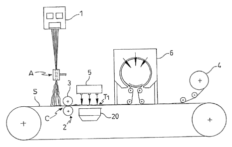
[0015]. With reference to figure 1, the method for
manufacturing spunbonded and/or carded nonwoven in
accordance with the present invention comprises the
following sequential steps:
a) laying at least one layer T1 of continuous thread
fibres or microfibres on a suitable support S;
b) treating said layer T1 such as to obtain an increase
in the thickness thereof by passing the layer T1 through
means of thickening which comprises two rollers 2, 3 and
at least one surface provided with ribs having an height
greater than 1 mm, a free head with a contact surface for
the fibres or microfibres having an extension of less
than 0,80 mm2, said ribs being distributed so that to
cover less than 14% of said at least one surface.
[0016]. Preferably, step b) takes place by means of
said thickening means which comprises two rollers 2, 3,
for instance of a conventional compactor or embosser, and
a support S having said particular surface, in contact
WO 2006/010766 CA 02578745 2007-02-28PCT/EP2005/053665
7
with said fibres, provided with the above described ribs.
[0017]. Moreover, the height of the ribs can preferably
be about 2 mm, the contact surface of the free heads of
the ribs can preferably be about 0.50 mm2 and the
distribution of the ribs can preferably be so that to
cover 7-9% on said surface.
[0018]. By the term "continuous thread fibres or
microfibres" is meant herein continuous fibres consisting
of one or more polymer components, either synthetic or
natural, optionally splittable into continuous-thread
individual microfibres, or filaments. Exemplary polymer
fibres splittable into microfibres are splittable multi-
component polymer fibres and exploded polymer fibres
which generate thinner fibres than those from which they
are derived in accordance with technologies which will be
discussed below.
[0019]. Step b) of treatment to obtain an increased
thickness of the nonwoven layer may be called, in other
words, "thickening", thereby meaning an operating step
allowing to turn the fibres or microfibres of a
spunbonded or carded nonwoven laid on a support in the
form of a thin, threadlike, and non-consolidated ply into
a non-consolidated or poorly consolidated ply (pre-
consolidation) of a cotton wool-like, thick, and soft
appearance.
WO 2006/010766 CA 02578745 2007-02-28PCT/EP2005/053665
8
[0020]. It has been surprisingly found that if the
thickening step of the nonwoven continuous-thread fibres
or microfibres is carried out on a rib-operated, i.e.
embossed, and however not smooth surface, the resulting
ply gains unexpected properties of softness and thickness
which are considerably increased compared to any other
nonwoven ply of the spunbonded or carded type.
[0021]. On the basis of this result, different variant
embodiments of a nonwoven of the spunbonded type, both
single-layer and multi-layer, have been provided.
[0022]. For the production of a single layer (figure
1), the manufacturing steps generally comprise feeding
the nonwoven layer T1 in the form of fibres or
microfibres by means of a spinneret 1 (extruder) coupled
to a conventional suction fan A, a hydro-entangling
station 5, a drying station 6 and a rewinding station 4
of the hydro-entangled layer on a roller.
[0023]. Particularly, step a) of laying a single layer
comprises, such as schematically represented in Figure 1,
extruding the nonwoven layer T1 in the form of continuous
thread fibres by means of a spinneret 1 (extruder) and
laying said fibres on a suitable support S by means of a
conventional suction fan A.
[0024]. Step b) of thickening is preferably carried out
by passing the layer T1, supported by support S, between
WO 2006/010766 CA 02578745 2007-02-28PCT/EP2005/053665
9
two rollers 2 and 3 of a conventional compactor or
embosser C.
[0025]. It should be noted that by the term compactor
or embosser is meant herein a device known per se, such
as described below, which has only the function of
changing the surface of a nonwoven ply thus obtaining a
slight consolidation (pre-consolidation) and, in the case
of embosser, such as to form patterns, writings or
drawings in relief. In other words, the compactor would
have a pre-consolidation function, actually weak, whereas
the embosser would have a preconsolidation and ornamental
function, thereby increasing the thickness of the ply. On
the contrary, the calender, though being provided with a
similar structure, has the basic function to consolidate,
and bond the fibres composing the nonwoven while
minimizing or at most maintaining the ply thickness being
laid down.
[0026]. Preferably, roller 2 of the compactor generally
has a thermoplastic smooth rubber surface for the layer
T1 to be pressed thereon, which layer is supported by
support S, by means of roller 3. Roller 3 is normally
made of smooth metal materials. Moreover, roller 3 is
heated to the polymer fibres melting temperature.
Accordingly, due to the mechanical action of both
rollers, the heating of polymer fibres and the three-
WO 2006/010766 CA 02578745 2007-02-28PCT/EP2005/053665
10
dimensional support S (mat interposed between both
cylinders) the thickening of the nonwoven layer T1 or, in
other words, a "volumizing effect", a "flimsy effect" is
surprisingly obtained. In the case where an ornamental
appearance is also desired, the embosser may be used,
where the support S has deeper, more marked ribs and
respective grooves, i.e. the ornamental matrix, such as
to obtain the desired ornamental effect.
[0027]. On the other hand, roller 3 in a conventional
calender is engraved, i.e. it has ribs in the form of
dots or dashes evenly alternating with grooves. In
particular, the ribs have a height comprised between 0.4
and 1 mm, a free head with a contact surface for the
fibres or microfibres of 0.88 mm2 and a distribution so
that to cover 19-23% of the surface of the roller. It is
to be noticed that said structure is just responsible of
a firm consolidation of the nonwoven ply.
[0028]. As already explained above, these ribs in the
calender act by forming melting points. Moreover, in the
calender, the nonwoven ply is not supported by any
support. On the contrary, either in the compactor device
or in the embosser, ribs on rollers are not provided. On
the other hand, there is provided a support S having a
three-dimensional surface which gives considerable
thickness, softness, and the above mentioned cotton wool-
WO 2006/010766 CA 02578745 2007-02-28PCT/EP2005/053665
11
like appearance.
[0029]. Support S can be a single continuous support
stretching beneath all the nonwoven working stations and
is advantageously provided with a surface in contact with
the fibres or microfibres, which is provided by ribs
alternating with grooves. Non-limiting examples of said
support S can be those represented in Figures 5a and 5b
where the contact surface with said fibres of microfibres
has a section with crimps or steps according to what has
been described in the international patent application
PCT/IT2004/000220 in the name of the same applicant.
Alternatively, the ribs can be either dots or dashes.
Furthermore, said ribs can be of any other known
conventional type such as truncated pyramid with
substantially squared base or truncated cone with oval or
circular base, the last one being the preferred shape.
[0030]. Accordingly, as described above, when the
nonwoven fibres are passed between two rollers 2 and 3
while being supported by a support S such as that
described above, the resulting ply acquires softness,
smoothness and thickness similar to cotton wool.
[0031]. It would appear that this particular effect is
due to the use of the support uneven surface which to
some extent would cause the cotton wool-effect of the ply
rather than the typical consolidation resulting from the
CA 02578745 2007-02-28
WO 2006/010766 PCT/EP2005/053665
12
calender, such as described above.
[0032]. In any case, the combination of the mechanical
(pressure and dragging) and physical (heating) actions
performed by the compactor C with the mechanical action
by the support S on the fibres is probably responsible
for the surprising result obtained.
[0033]. Accordingly, the effect described above can be
created by employing a support surface having ribs of
substantially any shape and that can be passed with
nonwoven fibres between the rollers of a compactor or
embosser according to conventional procedures. In any
case, the support S should be sufficiently solid to
withstand the operating pressure of rollers 2 and 3 and
withstand the fibre melting temperature.
[0034]. Therefore, the support S described above can be
a conveyor belt or tape made of any type of plastic
material which is normally used in the field. Preferably,
the support S is a metal sheet or a hard heat-resistant
plastic sheet. Preferably, support S can further consist
of a punched sheet through which the air can be sucked in
order to maintain the fibres adherent to said sheet while
they are being worked.
[0035]. This support S can alternatively be a closed
conveyor belt (not shown) limited to the level of rollers
2 and 3 of compactor or embosser C. Thereby, the fibres
CA 02578745 2007-02-28
WO 2006/010766 PCT/EP2005/053665
13
can be laid on a conventional support which carries said
fibres to said conveyor belt such as to deliver the
fibres thereto and allow the thickening treatment to be
carried out in the advantageous conditions described
above.
[0036]. Following the passage of ply T1 of spunbonded
and/or carded nonwoven supported by support S through
the compactor C, the ply T1 passes underneath the hydro-
entangling machine 5 to be consolidated (step c)) in
accordance with widely established methods. Subsequently,
the ply T1 is conventionally dried in dryer 6 (figure 1).
[0037]. In addition, such as shown in figure 1, the
fabric ply T1 can be wound around a winding roller 4,
also of the conventional type.
[0038]. The fibre forming the inventive nonwoven can
also be a non-continuous fibre (staple fibre)
manufactured by traditional carding machines such as 1,5
to 7 mm fibre in PES, PP, PLA, VISCOSE, LYOCELL, TENCELL,
or COTTON.
[0039]. Further technologies used to manufacture an
advantageous fibre according to the invention, comprise:
a. production of bi-component synthetic polymer fibres
(multi-seyments), that can be split with a hydro-
entangling machine;
b. production of synthetic polymer fibres with
CA 02578745 2012-05-25
14
explosion effect, for example polyester, polypropylene,
polyethylene (technology known as "Nanoval");
c. production of natural fibres with explosion (such as
Lyocell, PLA, etc.) by "Nanoval" technology described
above.
[0040]. Particularly, the single- or multi-layer
nonwoven can be of the hydro-entangled type based on
exploded continuous thread or splittable multi-component
continuous thread fibres. The nonwoven fibres generally
consist of only one component; however, for particular
applications they may also be manufactured in the
multi-component form, through the joint extrusion of
different polymers.
[0041]. For example, the multi-layer composite
nonwovens are those containing one or more nonwoven
layers, associated to a layer of cellulose fibres: in
such cases, the final composite advantageously combines
the mechanical properties of the nonwoven with the
absorbent properties of the cellulose fibres.
[0042]. The above technologies are described in the
patent application PCT/IT2004/000220 in the name of the
same applicant. Particularly, those technologies applied
to the thickening method in accordance with the present
invention are described herein. It should be noted that
WO 2006/010766 CA 02578745 2007-02-28PCT/EP2005/053665
15
the technologies relate to synthetic or natural polymer
fibres, either splittable or exploded in microfibres.
However, these fibres can be replaced with normal fibres
of the spunbonded type such as obtained by conventional
technologies or with carded fibres of the staple fibre
type, and they can be worked following the same steps in
accordance with the present invention such as described
in detail herein below.
1. Production of splittable synthetic polymer fibres
[0043]. For the production of a single layer, reference
is made to what is illustrated in Figure 1, where the
difference from the method described above is that the
spinneret 1 employed is herein a device, known per se,
which is capable of manufacturing polymer fibres
splittable into microfibres.
[0044]. For the details of each step, reference should
be made to the description below, with reference to
Figures 2, 3 and 4 in which the steps with similar names
are identical to those outlined above.
[0045]. The method for manufacturing a nonwoven,
according to this first variant embodiment of the
invention, comprises the manufacturing steps a) to b)
such as described above, in which the fibres laid in step
a) comprise splittable multi-component polymer fibres
which split into mono-component fibres by entangling to
WO 2006/010766 CA 02578745 2007-02-28PCT/EP2005/053665
16
one other during the consolidation step by hydro-
entanglement.
[0046]. According to a variant embodiment of the
invention, such as illustrated in Figure 2, the method
provides a further step of laying at least one layer of
absorbent material fibres T3 on said at least one layer T1
subsequent to the thickening step b), therefore the
hydro-entangling step takes place such as to obtain a
nonwoven in which the multi-component polymer fibres
split into mono-component micro-fibres entangle with one
another and with the fibres of the absorbent material.
[0047]. Generally, said method provides feeding the
nonwoven first layer T1 through a suitable spinneret 7,
one or more stations 8 for laying the cellulose pulp 80,
hydro-entanglement 10, drying 11 and rewinding on a
roller 12.
[0048]. On the other hand, the manufacture of a three-
layer composite in accordance with the invention (Figure
3a where the same reference numbers as those from Figure
2 designate similar operating equipment or stations)
generally provides feeding the first nonwoven layer T1
through a suitable spinneret 7, one or more stations 8
for laying the cellulose pulp 80, laying a second
nonwoven layer T2 through a suitable spinneret 9, hydro-
entanglement 10, drying 11 and rewinding on a roller 12.
WO 2006/010766 CA 02578745 2007-02-28PCT/EP2005/053665
17
[0049]. Referring to a multi-layer product, it is
widely known that splittable multi-component fibres may
be produced through extrusion by spinnerets of polymer
materials so as to form continuous fibres, in accordance
with the technology a. identified above. These fibres, on
output from the spinnerets, are hit by a jet of
compressed air that causes the elongation and the
electrostatic charging thereof such to cause a mutual
repulsion causing them to fall randomly onto a conveyor
belt.
[0050]. With reference to Figure 3a, a method for the
production of multi-layer nonwoven fabric comprising
outer layers made with splittable fibres according to the
abovementioned technology will be now described. In any
case, the subject method comprises the following steps:
a) laying at least one layer T1 of continuous thread
splittable multi-component polymer fibres on a suitable
support S;
b) treating said layer T1 such as to obtain an increase
in the thickness thereof as disclosed above;
c) laying on said at least one first layer T1 at least
one layer T3 of absorbent material fibres 80;
d) laying at least one second layer T2 of splittable
multi-component polymer fibres on said at least one layer
of absorbent material fibres T3;
WO 2006/010766 CA 02578745 2007-02-28 PCT/EP2005/053665
18
e) treating said layer T2 such as to obtain an increase
in the thickness thereof as disclosed above;
f) consolidate said layers Tl, T2 and T3 by hydro-
entanglement.
[0051]. Preferably, step b) and step e) take place by
said layer T1 and said layers Tl, T2 and T3r passing
between two rollers, respectively, onto a support having
a contact surface to said fibres being provided with ribs
alternating with grooves as specified above.
[0052]. As stated above, the hydro-entanglement of the
laid fibre layers takes place such as to obtain a multi-
layer nonwoven wherein the multi-component polymer fibres
are split into single mono-component micro-fibres
entangling with one another and with the fibres of the
absorbent material.
[0053]. Particularly, splittable multi-component
synthetic fibres can be formed by separately extruding
individual polymers in a molten state in the form of
threads 70, 90 exiting from orifices, of capillary
dimensions, of a spinneret 7, 9 and linking them beneath
the spinneret. The polymers at the molten state are
linked in a single fibre combined by extrusion of the
individual polymer threads in such directions to cause
the contact thereof and the adhesion thereof, such as
described in patent US 6,627,025. A suction fan A
WO 2006/010766 CA 02578745 2007-02-28PCT/EP2005/053665
19
positioned underneath the spinneret has the function of
sucking and conveying the individual threads of extruded
polymer in order to favour the bonding thereof into a
single fibre.
[0054]. The synthetic fibres may be composed of at
least two threads of a single polymer up to 16 threads of
different polymers (bi-component), be they homopolymers,
copolymers or blends thereof. The polymers may be
selected from polyesters, polyamides, polyolefins,
polyurethane, polyester modified with additives,
polypropylene, polyethylene, polypropylene terephthalate,
polybutylene terephthalate.
[0055]. Preferably, such polymers may be selected such
that in the fibres adjacent polymers cannot blend or in
any case have poor affinity in order to favour the
subsequent separation thereof. Alternatively, the
polymers may be additized with lubricants that prevent
the adhesion thereof. In addition, as the longitudinal,
axial portion of the fibre usually has a greater force of
cohesion than the peripheral portion, it may be
advantageous to spin multi-component fibres so as to
leave an axial hole or in any case a weakened axial
portion.
[0056]. As shown in figure 3a, once a layer of
splittable multi-component polymer fibres has been laid
WO 2006/010766 CA 02578745 2007-02-28PCT/EP2005/053665
20
through the special spinneret 7 onto a conveyor belt S
such as to create a first layer of spun-bonded nonwoven
T1, one layer of absorbent material T3 such as cellulose
pulp is laid on said layer of nonwoven .
[0057]. Subsequently, a second layer T2 of nonwoven
substantially identical to that prepared previously is
laid on the layer of cellulose pulp T3r such as
illustrated in Figure 3 at the station identified with
reference number 9.
[0058]. At this point, the fibres are subject to hydro-
entangling at the hydro-entangling station 10. This
treatment, widely known per se, advantageously enables to
split the polymer fibres that compose the nonwoven outer
layers nonwoven in micro-fibres and to entangle them with
one another and with the cellulose pulp fibres.
[0059]. Preferably, the hydro-entangling is made not
only on side Si of the support S on which the fibres are
laid but also on side S2r opposite side Slr through
special through holes (not shown in the figures) and
suitable equipment positioned on said side S2 (not
shown).
[0060]. Figures 1 to 3 also schematically represent a
conventional filtering device 20 for the water
originating from the hydro-entangling machines positioned
after the cellulose pulp laying step. Said device has the
WO 2006/010766 CA 02578745 2007-02-28PCT/EP2005/053665
21
function of recovering the water of the hydro-entangling
machine and filtering it of any cellulose pulp fibres
besides filtering the chemical components that are
contained in the fibres and may be released in the course
of hydro-entanglement.
[0061]. In accordance with a further variant embodiment
of the invention, Figure 3b illustrates a support S',
identical to that described above, on which the second
layer T2 of nonwoven fibres is laid. As will be seen,
said S' is at a different level from support S on which
the first layer T1 is laid. Thereby, the second layer T2
can be separately subjected to thickening (embossing).
Thickening only layer T2 is advantageous in that two
substantially even layers can be obtained.
[0062]. Subsequently to the thickening treatment, the
layer T2 is carried and laid on the layer of absorbent
material fibres T3r by support S' or by a conventional
conveyor belt, such as described above, and the three
layers are subjected together to hydro-entanglement.
[0063]. The drying step in the dryer 11 and the final
winding on roller 12 take place as described above.
2. Production of exploded synthetic polymer fibres
[0064]. The process for the production of nonwoven
based on exploded polymer fibres comprising the same
steps described with reference to the production of
WO 2006/010766 CA 02578745 2007-02-28PCT/EP2005/053665
22
nonwoven based on splittable polymer fibres, to which
reference should be made. In this case, the difference
lays in the type of technology adopted to manufacture the
fibre layers T1 and T2 which allows to obtain exploded
microfibres which, after they have been subjected to
thickening, entangle to one another and optionally with
the absorbent material fibres.
[0065]. According to Nanoval technology, the explosion
of the fibre (just extruded at the molten state) is
obtained when it comes into contact with air at room
temperature.
[0066]. Generally, as described in patent application
WO 02/052070, Nanoval technology consists in producing
molten polymer threads that protrude from spinning holes
arranged in one or more rows placed in a chamber with a
given pressure separated from the outside environment and
filled with gas, generally air. Said threads come to an
area of rapid acceleration of this gas when exiting from
the camera, the outlet being made in the form of a Laval
nozzle.
[0067]. The raw materials that can be spun are both of
natural origin, such as cellulose Lyocell, PLA, and
synthetic or such as polypropylene, polyethylene,
polyamide, polyester.
[0068]. With regards to the laying of the exploded
WO 2006/010766 CA 02578745 2007-02-28PCT/EP2005/053665
23
fibres to form a first layer and the further
manufacturing steps, the same references are valid as
made to figures 1, 2 and 3 in cui in which the suction
fan A is eliminated and the spinnerets 5, 6, 7 and 9 are
each fitted with the abovementioned Laval nozzle (not
shown) in order to obtain the explosion effect.
[0069]. The advantage of use of the Nanoval technology
lies in the possibility of producing very fine micro-
fibres with diameters of less than 10 pm, for example
between 2 and 5 pm.
[0070]. A further advantage also in relation to the
technology that employs splittable polymer fibres lies in
the fact that a greater density of individual micro-
fibres per each fibre is obtained. In other words the
fibre divides into a number of components at equal
initial diameters, i.e. the micro-fibres (filaments) that
are obtained are at least 10 times finer, preferably up
to 100 times finer.
[0071]. Regardless of the type of traditional
spunbonded or splittable or exploded fibre used, or
carded fibre, in the case one wishes to pre-entangle the
nonwoven before bonding it into the form of a multi-
layer composite (Figures 4a and 4b), the steps are as
follows: laying the first layer T1 by means of the
spinneret 13 or a carding machine, pre-hydro-entangling
WO 2006/010766 CA 02578745 2007-02-28PCT/EP2005/053665
24
through equipment 14, drying through equipment 15, laying
cellulose pulp T3 through equipment 16, laying the second
layer T2 through spinneret 17 or carding machine, hydro-
entangling with hydro-entangling machine 18, drying
through equipment 19 and rewinding onto a roller 21.
[0072]. The manufacturing method and plant may as well
provide a dewatering step or station 22 associated to the
drying step or station. The advantage of a pre-hydro-
entangling step is that it allows to create a first layer
of spunbonded polymer fibres, either split or exploded,
that, thanks to the greater density of the entangling of
the micro-fibres of said fibre, favours the laying of
fibres of absorbent material and prevents the partial
loss thereof through spaces too wide, which are left by
prior art technologies.
[0073]. As mentioned previously, the step of laying
fibres of absorbent material is preferably made with
cellulose pulp fibres having a length that may vary from
0, i.e. cellulose powder, to 2.5 mm, preferably from 1 to
2 mm.
[0074]. In addition, the process according to the
invention may provide a drying step after the hydro-
entangling step and, preferably also after the pre-hydro-
entangling step.
[0075]. A further step may consist in the elimination
CA 02578745 2007-02-28
WO 2006/010766 PCT/EP2005/053665
25
of the water contained in the fibres by means of a
dewatering step. Particularly, said step consists in
arranging a condenser 22 below support S and for example
at dryer 15 to which an entirely conventional suction fan
(not shown) is usually coupled up. The air sucked through
the holes made on said support is conveyed into said
condenser where it releases the water contained therein.
Equipment of this type is described for example in patent
application PCT/IT2004/000127 of the same applicant.
[0076]. The method may also comprise an embossing step
to make products with patterns of the multi-layer
nonwoven. Particularly, the embossing may consist in a
calendering treatment made by making the nonwoven being
heated and pass under pressure between a pair of engraved
rollers, in accordance with conventional techniques, or
through a further step in a hydro-entangling machine. It
should be noted that the term "embossing step" is not
referred to a consolidation of the nonwoven as occurs
according to the prior art mentioned previously but is
simply enabling to make captions and/or three dimensional
drawings in order to tailor or decorate the nonwoven
through a "thermo-embossing" or "hydro-embossing"
calender, in this case in the hydro-entangling process.
[0077]. Preferably, the process comprises sucking the
air at room temperature through the abovementioned
WO 2006/010766 CA 02578745 2007-02-28PCT/EP2005/053665
26
through holes (non shown in the drawings) made in the
support S for the fibres. In this way, the splittable or
exploded polymer fibres, laid at the molten state, are
cooled and cured. In the case in which exploded fibres
are used a humidifier HUM (schematically shown in Figure
3a and in Figure 3B) can be arranged for the exploded
fibres to be humidified immediately before laying them on
the support S either to favour or improve the softness of
the end product.
[0078]. Still more preferably, said method may comprise
one or more of the following final steps, known per se,
in order to increase or add additional characteristics to
the end product: coloring or finishing of a chemical
nature as the anti-pilling treatment and the hydrophilic
treatment, antistatic treatment, improvement of flame
proof properties, substantially mechanical treatments
such as napping, sanforizing, emerizing.
[0079]. In addition, the nonwoven may be subject to a
further process of multicolor printing using the
equipment described in patent application
PCT/IT2004/000127 in the name of the same applicant. In
this case, a nonwoven sheet at the end of the process
described above may be printed directly in-line following
the steps of:
- providing equipment for nonwoven printing comprising a
WO 2006/010766 CA 02578745 2007-02-28PCT/EP2005/053665
27
moving support for the transport of said nonwoven and at
least one moving print organ;
- feeding said nonwoven sheet to said equipment;
- performing the printing on said nonwoven under the
command and control of a command and control unit, in
which said command and control unit is operatively
connected with said support and at least one printing
organ in order to detect electrical signals originating
from said support and at least one print organ,
transforming said signals into numerical values
representative of the state of their angular speed and
torsional moment, comparing said numerical values with
ratios of preset numerical values of said angular speeds
and torsional moments and sending signals to said support
and at least one print organ in order to correct any
variation of said values that fall outside said ratios.
[0080]. Finally, the process in accordance with the
present invention may comprise a step of winding the
nonwoven onto a roller 21.
[0081]. The method of the present invention enables to
obtain various types of product:
[0082]. A. single-layer fabric with basic weight of
between 8 and 50 g/m2. The manufacturing method is such
as illustrated in Figure 1. The fibre used may be either
a synthetic fibre with explosion effect, as described
WO 2006/010766 CA 02578745 2007-02-28PCT/EP2005/053665
28
above and obtained according to the Nanoval technology,
or it may be a bi-component (multi-seyments) synthetic
fibre, splittable with a hydro-entangling machine, or a
natural fibre with explosion (for example, Lyocell, PLA,
etc.), also produced with "Nanoval" technology, or it may
simply be a normal spunbonded fibre.
[0083]. B. multi-layer fabric with single-layer
hydro-entangling or three-layer hydro-entangling with or
without pre-hydro-entanglement. For example, the product
may be a three-layer multi-layer one, of which one
central cellulose pulp layer and the outer layers with
different combinations of the technologies illustrated
above (20 to 200 g/m2).
[0084]. In any case, regardless of the type of single-
layer or multi-layer nonwoven, the tactile and visual
characteristics of the individual ply, either spunbonded
or carded, which forms it and differentiate it from any
other ply comprise, weights being equal, a 3-5 times
greater thickness, softness and smoothness similar to
cotton and a cotton wool-like appearance, i.e. similar to
a mellow and delicate flock, such as illustrated in
Figure 6B.
[0085]. On the contrary, such as illustrated in Figure
6A, the nonwoven for example spunbonded manufactured in
accordance with prior art has a threadlike appearance, is
CA 02578745 2012-05-25
29
compact, thin and without softness.
[0086]. Particularly, and by way of non-limiting
examples, exemplary fibres obtainable in accordance with
the inventive method are described below.
I. Splittable multi-component spunbonded polymer
synthetic fibres
[0087]. Preferably, the splittable multi-component
polymer fibres are composed of micro-fibres or filaments
of polymer such as those described above with reference
to the manufacturing method. The micro-fibres may have a
linear density of between 0.1 dTex and 0.9 dTex and the
corresponding fibres may vary according to the number of
micro-fibres that compose it but generally are of
dimensions of between 1.7 dTex and 2.2 dTex. The number
of micro-fibres in said fibres generally ranges between
2 and 16 (bi-component products).
[0088]. As to a three-layer nonwoven having an inner
layer of cellulose pulp fibres and two outer layers of
polymer fibres consisting of two different splittable
polymer components such as polypropylene/polyethylene,
analytical tests have shown the following physical
characteristics:
- weight in grams per square meter ranging
between 50 and 100, preferably between 55 and
65;
- tensile strength in the machine direction
WO 2006/010766 CA 02578745 2007-02-28 PCT/EP2005/053665
30
expressed in Newton per 5 cm (N/5cm) between 50
and 150, preferably between 60 and 120, whereas
in the cross-direction between 20 and 75, it is
preferably between 30 and 65;
- elongation, calculated as a percentage of the
length in a relaxed state, ranged between 35% and
85% in machine direction (MD), preferably between
45% and 75%, whereas it ranged between 70% and
100% in the cross-direction (CD), preferably
between 80% and 90%;
- final content of the cellulose pulp fibre
ranged between 50% and 75% of the total weight of
the nonwoven ;
- power of absorption calculated as a percentage
of total weight in relation to the weight of the
dry nonwoven was between 600% and 700%
(according to the percentage of pulp in the end
product).
II. Spunbonded exploded polymer synthetic fibres
[0089]. Referring to the exploded fibres, it has been
observed that the micro-fibres (filaments) have a
diameter ranging between 1 micron and 5 micron,
preferably between 2 and 4 micron. Obviously said values
may vary according to the type of preset characteristics
for the end product and will depend on the production
WO 2006/010766 CA 02578745 2007-02-28PCT/EP2005/053665
31
parameters selected, as described previously, and in any
case known to those skilled in the art.
[0090]. Regardless of the type of polymer fibres used,
the final thickness of the multi-layer nonwoven
advantageously reaches values of up to 0.65 mm and a
tensile strength of 27 N/5cm (in the manufacturing line
cross-direction).
[0091]. The products obtained according to the present
invention have a plus of resistance, softness, thickness
and have a better appearance. Besides the thickness is
increased either by the explosion effect (Nanoval
technology), or (splittable fibres) by the split effect.
Particularly, the abovementioned characteristics result
from the combination of the use of a support S such as
that described above to support a ply of fibres or
microfibres during the passage between both rollers of a
compactor or an embosser.
[0092]. Figure 5a shows a digital photograph of a 2,2
dtx polymer ply of the spunbonded type obtained in
accordance with suitable procedures. It can be seen that
the ply has a compact and thin appearance like a sheet of
tissue paper.
[0093]. Figure 5b shows a digital photograph of a 2,2
dtx polymer fibre ply of the spunbonded type obtained in
accordance with the method of the present invention. It
WO 2006/010766 CA 02578745 2007-02-28PCT/EP2005/053665
32
can be seen that the ply has a soft and thick cotton
wool-like appearance.
[0094]. A non-limiting example of one embodiment of the
process according to the present invention is described
below.
EXAMPLE
[0095]. Isotactic polypropylene polymer material has
been employed to carry out this example, having a melt
flow rate of 40 g/10 min, such as established by ASTM D-
1238, in the form of "chips". The polymer has been loaded
in an extruder connected to a spinneret having an
operating pressure of about 9646 kPa. The spinneret
consists of capillaries having a diameter of 0,038 cm and
a slot length of 0,152 cm. The molten isotactic
polypropylene passes through the spinnerets at a speed of
0.6 g/min/hole and is extruded at a temperature of 227 C.
The polymer is random laid on a perforated support having
a fibre-collecting surface provided with cube-shaped ribs
of 1 mm-long side and alternating with specular grooves.
Subsequently, the support is moved forward until reaching
two rollers of an embosser where it is pinched between
said rollers together with the non-consolidated polymer
fibre ply carried thereonto. The pressure applied by the
embosser, which normally ranges between 10 and 100N/mm,
is about 45N/mm whereas the operating temperature, which
WO 2006/010766 CA 02578745 2007-02-28PCT/EP2005/053665
33
normally ranges between 80 and 200 C, is 140 C the
rotation and dragging speed of the ply, which varies
between 20 and 600 m/min, is 300 m/min. At the calender
outlet, the consolidated ply has a cotton wool-like
appearance, is soft, has a weight in grams ranging
between 17 and 18 g/m2 and is up to five times thicker
than a spunbonded nonwoven of the same weight in grams,
which is usually no more than 0,18 mm thick. Now, the
continuous ply is winded on a roll to be then carried to
a subsequent manufacturing line or, in the case of in-
line operation, to the hydro-entangling station to be
subjected to the normal treating conditions. It should be
noted, however, that the end product does not exhibit
substantial modifications of the tactile, thickness and
functional characteristics such as described above.
[0096]. It should be appreciated by what has been
stated above that the present patent application provides
a method for manufacturing a particularly soft, smooth
and thick nonwoven, as well as a nonwoven obtainable by
said method.
[0097]. Furthermore, those of ordinary skill in the art
may carry out a number of modifications both to the
method and the nonwoven, all being within the scope of
protection of the claims appended herein.
[0098]. For example, the method may provide only the
WO 2006/010766 CA 02578745 2007-02-28PCT/EP2005/053665
34
first two steps a) and b), and the winding of the
spunbonded or carded nonwoven ply on a suitable winder,
such as illustrated in Figures 7 and 8, respectively.
[0099]. Particularly, in Figure 8 is schematically
represented a method for manufacturing a carded nonwoven
wherein the same reference numbers as the reference
numbers of the prior embodiments indicate the same
working stations.
[00100]. A carding machine 23 lays, in a fully
conventional manner, a nonwoven layer T1 on a support S
such as that described above. Subsequently, the support S
with layer T1 passes through the rollers 2 and 3 of
either the compactor or embosser C to be preconsolidated
and mainly to increase its volume, such as extensively
described above. Finally, said layer T1 is wound on a
roller 4.
[00101]. Referring to Figure 9 wherein the same
reference numbers as the reference numbers in Figure 3a
designate the same working stations, there is
schematically represented a manufacturing line or a
method for manufacturing a three-layer carded /cellulose
pulp/spunbonded mixed nonwoven.
[00102]. Compared to the method described in Figure 3a,
this method is different in that the first spinneret 7
for laying the first nonwoven layer T1 is replaced with a
WO 2006/010766 CA 02578745 2007-02-28PCT/EP2005/053665
35
conventional carding machine 23.
[00103]. Similarly, Figure 10 illustrate a schematic
view of a manufacturing method for a three-layer carded
/cellulose pulp/carded nonwoven wherein the spinnerets 13
and 17 from Figure 4a are replaced with two respective
carding machines 23.
[00104]. It should be noted that, also in this case, all
the variants discussed above are valid, i.e. the nonwoven
layers can be previously hydro-entangled, the second
nonwoven layer T2 can be laid and passed through the
compactor or embosser on a different level from any
previous laying of fibres and the above-mentioned
supplementary machining operations such as moulding and
decoration (thermo-embossing) may be provided.
[00105]. Furthermore, in the mixed multi-layer nonwoven,
either the first laid layer, such as illustrated in
Figure 9, or the second layer can be the carded layer.
[00106]. Consequently, according to the concept at the
heart of the present invention, the spinneret (extruder)
for manufacturing spunbonded fibres can be replaced with
carding machines, which are known to work with fibre
flocks (1,5-7cm long staple fibres such as PES, PP, PLA,
LYOCELL, TENCELL, COTTON). In this case, step b) of
treatment to provide the nonwoven ply with the above-
mentioned swollen appearance, a cotton wool-like
WO 2006/010766 CA 02578745 2007-02-28PCT/EP2005/053665
36
thickness and softness will be always obtained by
employing the compactor such as described above.
[00107]. Advantageously, the inventive method may
further provide the use of fibres or microfibres both of
the spunbonded type, such as discussed above, and fibre
flocks (staple fibres) which are typical of a carding
operation. As a result, the passage through a ply-
thickness increasing device, such as described above,
will be entirely similar.
[00108]. In addition, in Figure 11 there is illustrated
a manufacturing method in which a roller 24 of spunbonded
or carded staple fibres, treated only by a compactor or
embosser such as discussed above, is subjected to
machining in a different line, in accordance with what
has been already discussed above. Particularly, the
nonwoven ply T is unwound from roller 24 and subjected
for example to hydro-entangling by equipment 5, similarly
to what has been described above, then it is dried and
finally wound again on a roller 4'.
[00109]. Similarly to what has been illustrated in
Figures 2 and 3a, figures 12 and 13 represent identical
methods, wherein, again, a roller 24 of spunbonded or
carded staple fibres replaces the spinnerets and the
carding machines for laying said fibres, respectively;
the other machining operation remaining unchanged. In
WO 2006/010766 CA 02578745 2007-02-28PCT/EP2005/053665
37
both latter cases, the variant embodiments described
above may be also adopted, such as employing two rollers
carrying the same fabric of the type
spunbonded/spunbonded, carded spunbonded/staple fibres or
carded staple fibres/staple fibres treated by compactor
or embosser.
[00110]. With reference to figure 14, a further
embodiment of the invention consists in performing the
method disclosed on paragraph 15 wherein, in particular,
said at least one surface is the surface of one of the
rollers of the compactor or embosser. The provision of
the surface with ribs on one of said rollers allows to
avoid the support S disclosed above without altering the
result to be obtained, i.e. increasing the thickness and
softness of the nonwoven layer so that to look like a
cotton wool-like.
[00111]. In detail, the compactor C comprises two
rollers (only one is represented in figure 14) similar to
the rollers of a conventional compactor or embosser,
wherein the surface 200 of one roller 201 is provided
with ribs 202 having an height greater than 1 mm, a free
head with a contact surface for the fibres or microfibres
having an extension of less than 0,80 mm2, said ribs
being distributed so that to cover less than 14% of said
at least one surface. The ribs can be of the same type as
WO 2006/010766 CA 02578745 2007-02-28PCT/EP2005/053665
38
disclosed above with reference to the ribs of the support
S.
[00112]. In particular, said ribs 202 can have a
preferred shape substantially in the form of a frustum of
cone with a grater circular base attached to the surface
201, as can be better seen in figure 15.
[00113]. A further object of the present invention is a
compactor or embosser, of a conventional type, for the
treatment of nonwoven fibres and/or microfibres,
comprising means of thickening which comprises two
rollers (2, 3) and at least one surface provided with
ribs having an height greater than 1 mm, a free head with
a contact surface for the fibres or microfibres having an
extension of less than 0,80 mm2, said ribs being
distributed so that to cover less than 14% of said at
least one surface. In particular, said thickening means
comprises two rollers (2, 3) and a support (S) having
said at least one surface with ribs in contact with said
fibres or microfibres. Alternatively, the surface 200 of
one roller 201 of the two rollers (only one is
represented in figure 14) of a conventional compactor or
embosser is provided with ribs 202 having an height
greater than 1 mm, a free head with a contact surface for
the fibres or microfibres having an extension of less
than 0,80 mm2, said ribs being distributed so that to
WO 2006/010766 CA 02578745 2007-02-28PCT/EP2005/053665
39
cover less than 14% of said surface 200. The ribs can be
of the same type as disclosed above with reference to the
ribs of the support S.