Note: Descriptions are shown in the official language in which they were submitted.
CA 02578833 2007-01-22
WO 2006/019848 PCT/US2005/024903
PATENT
ULTRASOUND-ACTIVATED ANTI-INFECTIVE COATINGS
AND DEVICES MADE THEREOF
CROSS-REFERENCE TO RELATED APPLCIATIONS
This International Application claims the benefit of U.S. Application No.
10/896,193,
filed July 21, 2004.
FIELD OF THE INVENTION
The present invention relates generally to implantable medical devices having
a
biocompatible polymer coating for delivery of therapeutic agents. More
particularly, the
present invention relates to an implantable medical device having a
biocompatible polymer
coating including at least one therapeutic agent whereby the therapeutic agent
is released
from the coating by exposure to at least one of ultrasound energy and light
energy.
BACKGROUND OF THE INVENTION
Central vascular access devices (CVADs) are medical devices that are implanted
into
a patient's vascular system and are typically used in applications which
provide a means for
repeated access to a patient's vascular system. Applications for CVADs are
varied and
include, for example, intravenous feeding; intravenous drug delivery, and
extracorporeal
protocols. Specific applications include chemotherapy treatments, intensive
antibiotic
treatment, prolonged IV feeding, and extracorporeal blood treatmeiit
protocols, such as
hemodialysis, hemofiltration, and apheresis.
CVADs having an exterior component (located outside the skin of a patient) are
convenient to use and may be used safely by skilled practitioners who use
sterile camiulas to
access the CVAD and who provide sufficient maintenance in the form of regular
flushing and
dressing changes. However, an added risk of infection exists due to the
presence of the
exterior component. Specifically, the external component may serve as a route
of exposure to
airborne contaminants such as bacteria.
Total implantation venous access devices, also referred to herein as TIVADs
are a
variety of vascular access devices that are implanted into a patient's
vascular system but that
-1-
CA 02578833 2007-01-22
WO 2006/019848 PCT/US2005/024903
do not have any exterior components. The entire device is implanted under the
patient's skin.
TIVADs have become used more routinely, where possible, as opposed to other
central
vascular access devices (CVADs) having an exterior component. An example of a
TIVAD is
an arterial-venous (A-V) port used in accessing the circulatory system, for
example, in
performing dialysis treatments. The port is accessed through the skin by
percutaneous
placement of a HUBER needle or other connecting tube. An example of a
conventional port
is shown in FIG. 1. The A-V port, referred to generally as reference numeral
2, includes a
lumen catheter 4 coupled to one or more reservoir access port 6 via a catheter
comlector 8.
The catheter 4 resides in the vein. The port 6 includes an impenetrable
housing 10 defining a
reservoir for fluids. The housing 10 includes an opening for receiving a
plastic or metal disk
having a septum 12 in the center. The septum 12 is a needle penetrable
elastometric material
and acts as a portal to the reservoir. Further examples of commercial ports
include those
disclosed in U.S. Patent No. 5,399,168, or VAXGEL iinplantable ports
(available from
Boston Scientific, Natick,lVlA.).
TIVADs such as ports require less maintenance that other CVADs. For example, a
properly functioning port may require flushing only once a month. Furthermore,
no external
dressing is necessary for such ports. An advantage of using TNADs over other
CVADs is
the reduced risk of infection arising from the protective skin barrier which
prevents any
possible exposure to airborne contamination. A further advantage of TIVADs
over CVADs
generally is greater patient acceptance.
Risks associated with the use of CVADs include local complications such as
thrombosis and thrombophlebitis, as well as systemic complications including
embolisms,
puhnonary edema and bloodstream infections. Although the risk of infection is
reduced in
TNADs as compared to other CVADs, it is still possible for a patient to
experience an
infection at the port, particularly the area where the port is accessed.
The average time a TIVAD-type A-V port remains useful for A-V access is about
two
years. During these two years, infection will develop in around 20% of
patients, and often
leads to removal of the port. In this case, A-V access has to be
reestablished. Often, this
means fmding another site for A-V access and waiting a period of tiune of up
to three weeks
before a normal hemodialysis schedule can be resumed.
-2-
CA 02578833 2007-01-22
WO 2006/019848 PCT/US2005/024903
Infection of the A-V port has been recorded as a major cause of death in
patients
receiving dialysis treatments. There are principally three ways in which an
infection can be
introduced during A-V access set up or the hemodialysis procedure itself.
First, bacteria can
be implanted with the A-V access device itself during a break in aseptic
technique. Second,
bacteria may already be present on the surface of the device. Third, bacteria
can be
transmitted from external sources, such as central venous catheters and
needles. The entry
site for infection is typically the puncture site.
The course of treatment for infections related to CVADs depends upon the type
of
medical device, the condition of the patient, and the identity of the bacteria
causing the
infection. The most common infectious agents are: staphylococcus aureus,
pseudonaonas
aeruginosa, and staphylococcus epidermis. These agents have been identified in
over 75% of
all reported vascular infections. Both stapliylococcus aureus and pseudomonas
aeruginosa,
show high virulence and can lead to cliiiical signs of infection early in the
post-operative
period (less than four months). It is this virulence that leads to septicemia
and is one main
factor in the high mortality rates. Staphylococcus epidef=mis is described as
a low virulence
type of bacterium. It is late occurring, which means it can present clinical
signs of infection
up to five years post-operative. This type of bacterium has been shown to be
responsible for
up to 60% of all vascular graft infections.
Vascular port infections are difficult to treat with the standard course of
oral
antibiotic's. Accordingly, infections of this type often require total graft
excision,
debridement of surrounding tissue, and revascularization through an uninfected
route. It
would be advantageous for implantable medical devices, such as ports, to be
provided with a
mechanism to deliver a therapeutic agent to address such infections, at the
site of infection.
Generally, it is known that certain design parameters are critical to proper
delivery of
therapeutic agents. Typically, they are: (1) delivering the agent to the
target tissue; (2)
supplying the agent in the correct temporal pattern for a predetermined period
of time; and
(3) fabricating a delivery system that provides the desired spatial and
temporal pattern.
Controlled or sustained release delivery systems are inteiided to manipulate
these parameters
to achieve the aforementioned advantages when compared to conventional dosing.
A typical
-3-
CA 02578833 2007-01-22
WO 2006/019848 PCT/US2005/024903
drug concentration versus time profile for a conventional parenteral or oral
dosage form (A)
and an idealized sustained drug delivery system (B) might look as shown in FIG
2.
A disadvantage of presently available methods for providing therapeutic agents
on
medical device substrates is the lack of a means to control the rate of
release of the
therapeutic agent. For example, in conventional biodegradable polymers, a
steady state rate
or sustained release of drug occurs, based on, inter alia, the rate of
degradation of the
polymer. Accordingly, there is no control over the time or rate of delivery of
the therapeutic
agent. It is possible, using these systems, for the therapeutic agent to be
depleted by the time
it is needed by the patent. Thus, the patient is dosed with therapeutic agent
even if there is no
infection. Furthermore, an active infection may require a larger dose than is
delivered by
sustained release of the therapeutic (i.e. anti-microbial) agent.
It would therefore be advantageous, for an implanted medical device such as a
CVAD, in particular a TIVAD, to provide variable drug release, so as to
increase the dose of
the therapeutic agent when necessary to address an active infection.
SUMMARY OF THE INVENTION
The present invention provides a coating for a medical device including a
polymeric
structure including at least one therapeutic agent, wherein a rate of release
of the therapeutic
agent from the polymeric structure is regulated by in situ exposure of the
coating to at least
one of ultrasound energy and light energy. When used as a coating on a medical
device
implanted in a patient, the coating provides the therapeutic agent to the
patient on an as-need
basis.
In accordance with the present invention, an implantable medical device is
provided
including a vascular access device and a coating on at least one of an inner
surface and an
outer surface of the vascular access device. The coating includes: (a) a
polymeric
component including at least one of a light reactive moiety and a sound
reactive moiety; and
(b) at least one therapeutic agent releasably associated with the polymeric
component,
wherein a rate of release of the therapeutic agent is controlled by in situ
exposure of the
medical device to at least one of a light energy source and an ultrasound
energy source.
-4-
CA 02578833 2007-01-22
WO 2006/019848 PCT/US2005/024903
Also provided is a method of treating a patient including the steps of: (a)
implanting a
medical device of the invention intradermally into a patient in need thereof;
and (b) releasing
the therapeutic agent to the patient by intra- or extra- dermal exposure to at
least one of a
light energy source and an ultrasound energy source.
BRIEF DESCRIPTION OF THE DRAWINGS
FIG. 1 is a perspective view of a conventional implantable A-V port.
FIG. 2 is a graph showing a typical release profile for a conventional dosing
scheme
as compared to that of a sustained release dosing scheme.
FIGS. 3A and 3B are schematic representations of a cross-section of an
embodiment
of a coated medical device according to the invention.
FIGS. 3C and 3D are schematic representations of a cross-section of a further
embodiment of a coated medical device according to the invention.
FIGS. 4A and 4B are schematic representations of a cross-section of a fiirther
embodiment of a coated medical device according to the invention.
DETAILED DESCRIPTION OF THE INVENTION
The present invention is directed to a medical device including a coating
having a
polymeric component and a releasable therapeutic agent associated therewith.
The coating
uses one or more polymers to mechanically hold and/or chemically bond one or
more
therapeutic agents to the polymer. The coatings are placed on at least part of
inner and/or
outer surfaces of a medical device, preferably a TIVAD, before implantation
into a patient in
need thereof. The rate of release of the therapeutic agents is controlled by
exposure to at least
one of a light or an ultrasound energy source.
Suitable Polymers
Those polymers useful in preparing coatings of the present invention include a
wide
variety of known polyniers. Although the mechanism of action of the individual
polymer-
therapeutic agent combinations may differ, common among the polymers used in
the present
-5-
CA 02578833 2007-01-22
WO 2006/019848 PCT/US2005/024903
invention are the properties of chemical and physical stability, biological
inertness, and
processability. Further desirable properties for use in coating the septum
part of an A-V port,
include a low glass transition temperature which provides the characteristic,
inter alia, of
pliability.
Useful polymeric materials include polymers, copolymers, block polymers and
mixtures thereof. Among the known useful polymers or polymer classes which
meet the
above criteria are: poly(glycolic acid) (PGA), poly(L-lactic acid) (PLLA)
(PLA),
polyoxalates, poly(a-esters), polyanhydrides, polyacetates, polycaprolactones,
poly(orthoesters), polyamino acids, polyurethanes, polycarbonates,
polyiminocarbonates,
polyamides, poly (alky cyanoacrylates), and mixtures and copolymers thereof.
Additional
useful polymers include, stereopolymers of L- and D-lactic acid, copolymers of
1, 3 bis(p-
carboxyphenoxy) propane and sebacic acid, sebacic acid copolymers, copolymers
of
caprolactone, poly(lactic acid)/poly(glycolic acid)/polethyleneglycol
terpolymers,
copolymers of polyurethane and poly(lactic acid), copolymers of a-amino acids,
copolyrners
of a-amino acids and caproic acid, copolymers of a-benzyl glutamate and
polyethylene
glycol, copolymers of poly succinic acid and poly(glycols), polyphosphazene,
polyhdroxy-
alkanoates and mixtures thereof. Binary and ternary systems are contemplated.
Preferred are poly(ethylene oxide) (PEO), poly(ethylene glycol) (PEG),
poly(propylene glycol) (PPG), poly (L-lactic acid) (PLLA), poly(s-
caprolactone), poly(a-.
amino acids), polyurethanes, poly(vinyl alcohol) (PVA) poly(vinyl
pyrrolidone), poly
hydroethyl methacrylate, and copolymers and block polymers thereof.
Some exemplary polymers which can be used in forming coatings for use in the
present invention may be generally categorized as follows:
1. Polyesters
a) poly (c - caprolactone) (PCL):
0
/CHZ,, /CH2
CH2 CHZ O
-6-
CA 02578833 2007-01-22
WO 2006/019848 PCT/US2005/024903
b) poly (glycolic acid) (PGA):
0
CH2
c) poly (L-lactic acid) (PLLA):
0
CH
I n
CH3
d) poly (lactic acid-co-glycolic acid) (PLGA):
0
o cx2
CH~ c~ o
I x 'o y Z
CH3
e) poly (lactic acid-co-e-caprolactone) (PLACL):
0
CH --*' O (CH2)5 --Ir O
I Q y
X
CH3
U. Poly (ethylene glycol), PEG block copolymers (also referred to as
poly(ethylene
oxide) (PEO)
a) PLA-PEG diblock copolymer:
0
O /CH2 1-1 CH21~1 O
CHZ O C2 OR
x y
CH3
-7-
CA 02578833 2007-01-22
WO 2006/019848 PCT/US2005/024903
b) PLA-PEG-PLA triblock copolymer:
CHCH2-0 CH2-CH~0 CH' CH2-0
YO. O
2 2 y 2
CH3 CH3
c) Poly (orthoesters):
0 0
O O DCOC
x
Within aqueous environments, the ortho ester groups are hydrolyzed to form
pentaethyritol
and proprionic acid. This is controlled by introducing basic or acid
components into the
matrices.
III. Polyanhydrides
a) poly[1,3 bis(p-carboxyphenoxy propane)], where x= 3
poly[l, bis(p-carboxyphenoxy hexane)], where x = 6
o O
O-- O~CHP
x
b) poly (sebactic anhydride):
O
/CH2\ /CHa\ /CH2\ /CHz
O CHZ CHZ CHZ CHz
O
x
IV. Poly(acrylic acid) (PAA) and derivatives, and vinyl polyrners thereof, for
example:
a) R= H- or CH3-(methacrylic)
R' = H- or HOCH2CH2-
-8-
CA 02578833 2007-01-22
WO 2006/019848 PCT/US2005/024903
R
CH2 Cj n
O';~ C'-OR'
b) R= H- or CH3-
R' = -CH2 CH(OH)CH3, -CH(CH3)2
CH2"I
C
n
O CNI4
I
R'
c) Polyvinyl alcohol (PVA):
cH2
~CH
I
OH
n
d) Poly(ethylcne-co-vinylacetate) (PEVAc):
CH2 CH2\
y z
CHZ (
X O
I
H3C~ O
See, for example, Proceeding of the 28th International Syrnposium on
Controlled Release of
Bioactive Materials, San Diego, CA, C. Aschkenasy and J. Kost, p. 311-312
(June 2001).
V. Poly(arnino acids) and copolymers
(a) poly (lysine):
-9-
CA 02578833 2007-01-22
WO 2006/019848 PCT/US2005/024903
O H
CH N
/ CH2
HZC\
~CHz
H2C
NH2
b) Poly (lactic acid-co-lysine):
O/C H O\C~ I H\N
0 4CH3
CH Ip j HZ X CH2
HZ
HZC\
NH2
VI. Polyurethanes and block copolymers
a) R = (CH2)õ
n = 4-6
O
u
R'1~1 N1-11 CO
1
H
Coinmercially available polyurethanes include BIOMER, ACUTHANE (available from
Dow
Chemical Co., PELLETHANE (available from Dow Chemical Co., Wilmington, DE),
and
RIMPLAST.
VII. Poly(dimethylsiloxanes)
CH3
Si-O
CH3
n
-10-
CA 02578833 2007-01-22
WO 2006/019848 PCT/US2005/024903
Further examples of suitable commercially available polymers include: PLURONIC
(available from BASF Corp., Ludwigshafen, Germany); MEDISORB, ELVAX40P
(ethylene
vinyl acetate) and BIODEL (available from Dupont Corp., Wilmington, DE); and
Polymer
No. 6529C (Poly(lactic acid)) and Polymer No. 6525 (poly(glycolic acid))
available from
Polysciences Inc., Warrington, PA.
In one aspect of the invention, polymers used are polyvinyl alcohol (PVA),
polyvinyl
pyrrolidone, polyethylene oxide, polyhydroxyethyl methacrylate alone or in
combination.
In a preferred aspect of the invention, the polymers are FDA approved for use
in the
body. Mixtures of polymers as well as layers of polymers are contemplated in
the coatings
used in the present invention. As will be discussed furt.her herein, known
polymers may be
used or be derivatized so as to provide a coating in which the rate of release
of a therapeutic
agent contained therein can be controlled, directly at a point of infection.
Polymer Systems Useful in the Invention
Known polymer systems which mechanically hold therapeutic agent therein,
deliver
the agent in a controlled release fashion based on the structural and
morphological
configuration of the polymer. Specifically, transport of particles (such as
therapeutic agents)
through pores in polymeric membranes occurs by mass transit mechanisms such as
diffusion
and convection. The mass transport of particles depend on whether or not the
polymeric
structures contain pores, and if so, what size pores. Macroporous membranes
having
relatively large pores in the range of about 500 angstroms to about 1.0
microns rely primarily
on convection to release particles. Examples of polymeric materials which can
form
macroporous membranes include polyurethanes, polyethylene glycol/poly
propylene glycol
copolymers and poly(lactic- co-glycolide-polyethylene).
In microporous polymer systems, in which the pore size is from about 100
angstroms
to about 500 angstroms, transport phenomenon is restricted by the geometric
characteristics
of the porous structure and by solute in the pores partitioning the pore
walls. Examples of
polymeric materials which can form microporous membranes include ethylene
vinyl acetate
copolymer loaded with macro molecular therapeutic agent. See, for example,
Rhine et al., J
of Pharmaceutical Sci., 69: 265-263 (1980).
-11-
CA 02578833 2007-01-22
WO 2006/019848 PCT/US2005/024903
Non-porous polymer systems, such as hydrogels, have internal structure based
on
molecular chains of entangled, cross-linked or crystalline chain networks in
the polymer. As
used herein a "hydrogel" is a polymeric material that swells in water without
dissolving and
that retains a significant amount of water in its structure. Hydrogels may
deform elastically.
The space between macromolecular chains is the mesh size. In these polymer
systems,
diffusion can be regulated to a certain extent by controlling the geometric
factors such as
thickness and surface area of the polymeric structure, and physiochemical
parameters related
to permeability of solute through the membrane. Controlling characteristics of
the polymeric
structure such as crystalline phase, porous structure, degree of swelling,
additive
concentration, mesh size of cross-linked macromolecular chains, and
thermodynamic
glassy/rubbery transitions, can be used to control diffusion. In particular,
cross-linking
and/or entangled polymer chains produces a screening effect to reduce the rate
of diffusion.
Hydrogels useful in the present invention include, for example,
polyhydroxyethylmethacrylate, polyvinyl alcohol and the like.
Another form of polymeric system is the reservoir system in which a polymeric
membrane surrounds a core of therapeutic agent. In this embodiment, a porous
or non-porous
polymer encapsulates therapeutic agent within micro- or nano- particles, which
form micro-
containers or micelles for the therapeutic agent. Non-limiting examples of
preferred
polymers for use in this embodiment include poly(ethylene glycol) (PEG),
poly(acrylic acid)
(PAA) and poly(vinyl alcohol) (PVA) or co-polymers or block polymers thereof.
See, for
example, Tian and Uhrich, Polymer Preprints, 43(2): 719-720 (2002).
Preferably, the
polymer is amphiphilic, containing controlled hydrophobic and hydrophilic
balance (HLB)
which facilitate organization of the polymer into circular micelles. The
therapeutic agent is
contained in the inicelles for later release. Examples of suitable reservoir
systems include
hydrogels such as swollen poly(2-hydroxyethyl methacrylate) (PEMA), silicone
networks,
ethylene vinyl acetate copolymers and the like. See, for example, Pedley et
al., Br. Polymer
J.,12: 99 (1980). Further examples include polyvinyl alcohol, polyvinyl
pyrrolidone, and
polyethylene oxide.
Furthermore, known polymer systems which chemically degrade so as to release
therapeutic agent contained therein may be adapted for use in the invention.
Specifically,
polymer systems referred to as polymeric matrixes possess characteristics
which promote
-12-
CA 02578833 2007-01-22
WO 2006/019848 PCT/US2005/024903
chemical degradation or erosion of the polymer to release therapeutic agent.
Chemically,
there are three mechanisms for polymer erosion from a bulk matrix. First,
degradation of
cross-links can free polymer chains from the bulk matrix. Second,
solubilization of water-
insoluble polymers can occur as a result of hydrolysis, ionization, or
protonation of a side
group. Third, degradation of labile backbone bonds attached to the backbone
structure of the
polymer ch~4n. In this mechanism, polymers having hydrolytic labile backbone
or side
chains contribute to the process of degradation.
Degradation of cross-links is possible if the polymer includes or is
derivatized to
include labile moieties in the cross-linkers such as ester or amide functional
groups. Any
polymeric material may be derivatized to include such labile portions using
methods
generally known to one having ordinary skill in the art.
Examples of polymeric matrix materials exhibiting the second type of chemical
degradation include those including a pendant group that may be solubilized.
Specific
polymers of this type include poly(L-lysine-co-polyethyleneglycol),
poly(methacrylic acid-
co-methacryloxyethylglucoside) and poly(methacrylic acid-co-ethyleneglycol).
Examples of polymeric matrix materials exhibiting the third type of chemical
degradation include high molecular weight water-insoluble polymers having
labile bonds in
the polymer backbone. These labile bonds become cleaved and the cleaved
portion of the
polymer is converted to small, water-soluble molecules. Alternative, a
percolation technique
breaks the backbone bonds causing the volume of the polymer to increase and
allow
therapeutic agent captured therein to flow out of the polymer. Examples of
such bioerodible
polymers include polylactic acid (PLA), polyglycolic acid (PGA) and
lactic/glycolic acid co-
polymer, polyamides, poly(c-caprolactone), poly(orthoesters), and
polyanhydrides. Further
non-limiting examples of suitable polymers in forming the matrix include
polyanhydrides,
ethylene-vinyl acetate, poly(lactic acid), poly(glutamic acid), poly(e-
caprolactone),
lactic/glycolic acid copolymers, polyorthoesters, polyamides and the like. Non-
degradable
polymers include ethylene-vinyl acetate and silicone.
Alternatively, it is possible to link a photosensitizer to a polymer backbone
or side
chain of the backbone using an appropriate linker which, when exposed to an
appropriate
-13-
CA 02578833 2007-01-22
WO 2006/019848 PCT/US2005/024903
light energy, will react to release the therapeutic agent associated
therewith. In this
embodiment the therapeutic agent may be linked via a side chain to the polymer
backbone
and the photosensitzer may be linked to the same or different polymer backbone
in the
vicinity of the therapeutic agent. It is also possible to attach a
photosensitizer directly to the
therapeutic agent, or to interpose a photosensitizer between a linker and a
therapeutic agent.
Examples of polymers suitable for use in this embodiment include co-polymers
of N-(-2
hydroxypropyl) methacrylamide and an enzymatically degradable oligopeptide
poly (L-
lysine-copolyethylene glycol).
In each of these known polymer systems, once the design criteria has been
selected, it
has not heretofore been known to modify the polymeric configuration ira situ
to alter rates of
release of a therapeutic agent contained therein after implantation.
Heretofore these polymer
systems either did not erode at sufficiently high rates to deliver sufficient
dosages or released
the therapeutic agent too quickly. Additionally, although the Langer reference
shows a
compressed implant of a polymeric structure which is implanted independent of
a medical
device, it has not been known to coat a medical device with a polymeric
material in which
release rates of a therapeutic agent contained therein may be regulated and
the therapeutic
agent delivered directly to the location of the infection without first having
to be circulated
throughout the system. Thus, although the known polymeric systems may degrade
over time,
or the polymeric systems may release a therapeutic agent through diffusion
through pore
structures, or implanted polymeric blocks may be treated to release
therapeutic agent
therefrom, it has not until now been shown that a coated medical device may be
exposed in
situ to an energy source so as to immediately direct the release of a
therapeutic agent at the
site of an infection.
Ultrasound Responsive Polymeric Materials
As used herein, the term "ultrasound" or "ultrasound energy" refers to a
mechanical
("acoustic" or in terms of "pressure") wave in a medium in a frequency range
of from about
16 kHz to about 1 GHz. Ultrasound is a longitudinal wave form with the
direction of
propagation being the same as the direction of oscillation. The effects of
ultrasound energy
generally include compression and expansion of the propagation medium at
approximately
one half a wavelength distance from the wave source. This causes pressure
variations in the
medium. The wavelength of ultrasound is expressed by the relationship:
-14-
CA 02578833 2007-01-22
WO 2006/019848 PCT/US2005/024903
Xf= C
where:
X = wavelength
f = frequency
C = speed of propagation
It is possible to direct sufficient ultrasound energy to a particular location
in the body
by accounting for the mass density of the tissue being penetrated and the
related half value
depth. By applying ultrasound waves perpendicular to homogeneous tissue (i.e.,
skin), it is
possible to calculate the absorption, coefficient which indicates the
intensity of absorption in
the tissue, as follows:
I(X)=I0 =ea"
where:
I(X) = intensity at depth X
Io = intensity at the skin surface
a = absorption coefficient
Generally, release rate is proportional to the intensity of the applied sound
wave. By
knowing the intensity of the wave at the surface of the skin, an absorption
coefficient for a
known depth of X can be realized by solving the above equation for a. A
parameter relating
to absorption is the half-value depth (D1i2) which is the distance in the
direction of a sound
beam in which the intensity in a certain medium decreases by half. For slcin,
the Dli2 is 11.1
mm at 1 MHz and 4 mm at 3 MHz.
The effects of ultrasound are related to several different physical mechanisms
including thermal heating, cavitation and streaming. In thermal heating, part
of the
ultrasound energy applied to a polymer will be converted into heat. For
example, exposure of
soft tissue to an ultrasound beam of an intensity of 1 W/cmZ can result in a
rise in temperature
of 0.5 C/s if heat conduction is discounted. Using ultrasound energy to cause
controlled
localized thermal heating will generate heat induced changes, including but
not limited to
breaking of cross-linking bonds, in the polymeric material. The application of
heat under
-15-
CA 02578833 2007-01-22
WO 2006/019848 PCT/US2005/024903
controlled conditions will thereby regulate the rate of release of the
therapeutic agent by
controlling the rate of diffusion of the therapeutic agent from the polymeric
material, the rate
of degradation of the polymeric material or a combination thereof.
In cavitation, application of ultrasound to a liquid or quasi-liquid medium
gives rise
to activity involving gaseous or vaporous cavities or bubbles in the medium.
Cavitation may
require pre-existing nuclei or bodies of gas stabilized in crevices or pores
or by other means
in the medium. Both stable and transient cavitation are possible. In stable
cavitation, gas
bubbles of a size that are resonant in the sound field generated oscillate
with large amplitude.
The expansion and contraction of the bubble which oscillate with the
ultrasound pressure
cycle causes the surrounding medium to flow in and out with a higher velocity
than if the gas
bubble were absent. The resonant diameter of a cavitation bubble in water at 1
MHz is about
3.5 microns. Pulsating gas bubbles resulting from such resonation are
asymmetric at the
air/liquid interface. The surface of such a pulsating asymmetric oscillation
bubble causes a
steady eddying motion to be generated in the immediate adjoining liquid, often
called
microstreaming. This pulsating results in localized shearing action which is
strong enough to
cause fragmentation of internal structures of the polymer. For example, main
chain rupture
may be induced by shock waves during cavitiation of the liquid medium.
Acoustic streaming is the unique property of acoustic wave propagation in
which time
independent flow of fluid is induced by the sound filed. Without intending to
be limited to
any particular theory, it is believed that streaming is related to the
conservation of molnentum
dissipated by the absorption and propagation of the wave. As a result of
streaming, physical
effects such as enhanced transfer of heat and mass, changes in reaction rates,
and
depolymerization are possible. Accordingly, using ultrasound energy to cause
cavitation
and/or microstreaming in a polymer system will cause the controlled alteration
in structure,
such as fragmentation and expansion of pore structures, so as to increase the
rate of diffusion
of the therapeutic agent from the polymeric material.
Additionally, chemical changes are commonly produced by cavitation. Again,
without intending to be limited to any particular theory, it is believed the
combination of high
pressures and temperatures can generate aqueous free radicals and hydrated
electrons (highly
reactive chemical species) within the exposed medium by the dissociation of
water vapor in
-16-
CA 02578833 2007-01-22
WO 2006/019848 PCT/US2005/024903
the bubble during its contraction. Chemical reactions of the resultant free
radicals
(particularly'=H and -OH radicals) with the polymeric structures are
sufficient to increase the
rate of degradation of the polymeric stractures to release the therapeutic
agent. Using
ultrasound energy to cause chemical changes in a polymeric system will cause
the controlled
.5 degradation of polymeric infrastructure by increasing the rate of release
of the therapeutic
agent from the polymeric material.
Although deep body tissue is generally opaque to light, it is usually
penetrable by
ultrasound waves. Accordingly, ultrasound waves emitted from a focused
ultrasound
transducer or a phased array can be concentrated at any location in the body.
Depending on
the frequency, the ultrasound transducer can cause cold cavitation, localized
heating and/or
streaming effects on a polymer at the focal point of exposure. Thus, it is
well within the
purview of the invention to initiate temperature, mechanical and/or chemical
related release
of therapeutic agent from a polymeric material by exposure to ultrasound.
In one embodiment of the invention, ultrasound is applied to a coating on a
medical
device sufficient to cause a localized and controlled temperature, mechanical
and or chemical
effect on at least a portion of the coating, thereby regulating the rate of
diffusion of the
therapeutic agent from the polymeric material, the rate of degradation of the
polymeric
material or a combination thereof. Accordingly, the rate of release of the
therapeutic agent
contained therein is regulated based on the frequency, duration and intensity
of the applied
wave.
In this=embodiment, a polymeric material including a releasable therapeutic
agent is
exposed to ultrasound energy under conditions and for a time to cause at least
one of the
effects discussed above, sufficient to release the therapeutic agent at a
desired rate.
Rate of release of therapeutic agent from the polymeric material can be
regulated by
varying one or more of the intensity, frequency or duration of the applied
ultrasound energy.
There are no particular limitations to the frequency, duration and intensity
of the applied
wave provided the combination is sufficient to provide the desired rate of
release of the
therapeutic agent while preserving the structural integrity and functionality
of the medical
device substrate or substrates and the therapeutic agent.
-17-
CA 02578833 2007-01-22
WO 2006/019848 PCT/US2005/024903
Preferably, the ultrasonic energy is generated from an ultrasound transducer.
The
range of intensity of ultrasound effective for producing short-term
therapeutic agent release
from a polymeric material is preferably from about 0.1 W/cm2 to about 30
W/cma, more
preferably from about 1 W/cm2 to about 50 W/cm~. As stated above, the rate of
release of the
therapeutic agent is proportional to the intensity of the applied sound wave.
Thus, it is
possible to increase the intensity of the applied ultrasound energy to
increase the rate of
release.
Preferably, the ultrasonic energy is delivered in the frequency range of from
about 20
kHz to about 10 MHz and is delivered through the skin to the implanted medical
device.
Preferably, the frequency is in the range of from about 50 kHz to about 200
kHz. For the
purposes of maximizing cavitation effects, preferably the frequency used will
be about 2.5
MHz.
Duration and/or pulse cycle of the wave form will also have an effect on the
amount
of therapeutic released per exposure event. The duration of exposure may also
be varied to
regulate the rate of release. Although there is no particular limitation to
the duration of
exposure, for the comfort and convenience of the patient, it is desirable to
minimize the time
of exposure. Suitable times may range from a few seconds continuous or pulsed
to an hour or
more. Preferably, the exposure shall be from about 20 seconds to about 10
minutes,
continuous or pulsed. It is possible to generate release rate curves for a
particular polymer
and therapeutic agent combination so as to be able to know the amount of time
necessary to
achieve the desired amount and/or rate of release of the therapeutic agent.
There are no particular limitations to the polymeric material used in these
embodiments except that it should, without exposure to ultrasound or light,
resist substantial
erosion for at least about six months, preferably at least about one year.
In one aspect of the invention, the polymeric material used in the coating
will have a
sufficient number of temperature labile bonds therein so that exposure to the
elevated
temperatures contemplated from localized heating, results in an increase in
the rate of release
of therapeutic agent.
-1~-
CA 02578833 2007-01-22
WO 2006/019848 PCT/US2005/024903
Further, in another aspect of the invention, in order to take advantage of
cavitation
related effects, the polymer will preferably have pores including air bubbles.
In this aspect of
the invention, it is desirable for the polymeric material to include a micelle
surrounding, a
therapeutic agent and include air bubbles therein. Preferably, the micelles
are from about
0.01 to 100 microns in diameter and have a gas volume therein of from about 5%
to about
30% of the volume of the micelle. Preferably, the therapeutic agent is a light
activatable
drug. See, for example, U.S. Patent No. 6,527,759, which is herein
incorporated by
reference. Additional limitations to this embodiment include the medical
device surface or
substrate which is coated should be stable at the localized temperatures used
to effect release
of the therapeutic agent. Furthermore, the therapeutic agent used should be
stable at any
elevated temperatures used to either polymerize the polymeric material or to
coat the medical
device. Preferably, the polymeric material may be cured at or about room
temperature.
In one aspect of the invention, polymers which readily release therapeutic
agent
through diffusion through a polymeric matrix may be derivatized using a cross-
linking agent
to include cross-linked internal structure which will degrade upon exposure to
ultrasound
energy.
In one aspect of the invention, a polymeric material used in the coating
includes
bonds which break upon exposure to localized elevated temperature from
exposure to
ultrasound energy. Examples of such bonds include ester or amide introduced
into the
polymer by side chain reactions such as esters or acids with amine. Examples
of polymeric
materials suitable for use in this embodiment include, but are not limited to,
poly(L-lysine-
co-polyethyleneglycol), poly(methacrylic acid-co-methacryloxyethylglucoside)
aiid
poly(methacrylic acid-co-etliyleneglycol), polylactic acid (PLA), polyglycolic
acid (PGA),
polyamides, poly(e-caprolactone), poly(orthoesters), and polyanhydrides.
Further non-
limiting examples of suitable polymers in forming the coating include
polyanhydrides,
ethylene-vinyl acetate, poly(lactic acid), poly(glutamic acid), poly(e-
caprolactone),
lactic/glycolic acid copolymers, polyorthoesters, polyamides and the like.
Suitable cross-
linlcing agents will be apparent to those having skill in the art.
In a fiu-ther aspect of the invention, the polymeric material used in the
coating
includes pores which, when exposed to ultrasound energy, react by forming
localized changes
-19-
CA 02578833 2007-01-22
WO 2006/019848 PCT/US2005/024903
in the internal configuration of the pores so as to enlarge the pores and
release therapeutic
agent contained therein. Examples of polymeric materials suitable for use in
this
embodiment include, but are not limited to polyethyleneglycol/polypropylene
glycol
copolymers and poly(lactide-co-glycolide polyethyleneoxide).
In another aspect of this embodiment, the polymeric material is derivatized to
include
temperature sensitive bonds so as to increase reactivity upon exposure to the
localized
elevated temperatures used to release the therapeutic agent. In this
embodiment, the
polymeric material is derivatized to contain an ultrasound reactive component
which, when
exposed to ultrasound energy, will effect a controlled increase in the rate of
release of the
therapeutic agent from the polymeric material.
In a still further aspect of the invention, the polymeric material used in the
coating
includes both bonds and pores which react upon exposure to ultrasound energy
so as to
release therapeutic agent.
Photoreactive Polymeric Materials
In another embodiment of the invention, a coating is provided on a medical
device
that is photoreactive or derivatized to contain a photoreactive moiety. Most
organic reactions
are carried out between molecules in the ground state. However, photochemical
reactions,
utilizing light of a specific wavelength range, promote molecules to an
electronically excited
state. Electrons can move from the ground-state energy level of the molecule
to a higher level
with this application of outside energy. The physical processes undergone by
excited
molecules include excitation, vibrational relaxation, intersystem crossing,
singlet-singlet
transfer or triplet-triplet transfer (photosensitization), and the like.
Some compounds will assume excited triplet states upon excitation by exposure
to a
certain wavelength of light. These compounds ("sensitizers" or
"photosensitizers") can
interact with various other compounds ("acceptors") and transfer energy to or
electrons from
the acceptors, thus returning the sensitizer to its unexcited or ground state.
Most compounds
will assume the excited singlet upon excitation. A photosensitizer in its
triplet state is
capable of converting ground-state oxygen (a triplet) to an excited singlet
state. See Singlet
Molecular OxygLen, A. Schaap Ed., Dowden, Hutchinson and Ross, Stroudsburg, PA
(1976).
-20-
CA 02578833 2007-01-22
WO 2006/019848 PCT/US2005/024903
The singlet oxygen can result in sufficient energy to alter electron states of
surrounding
materials and to cause bonds in those materials to break.
It is possible to link a photoreactive compound or photosensitizer to a
polymer
backbone using an appropriate linker, which when exposed to an appropriate
light energy,
will react to release the therapeutic agent associated therewith. For example,
it is possible to
bind photosensitizers to therapeutic agents having aliphatic amino groups to
form
photoreactive/therapeutic agent complexes. Polymer backbones or co-polymer
precursors
may be derivatized to contain co-polymer side chains or "linkers" having
active ester
functionalities. The aliphatic amino groups of the complexes may be bound to
the active
ester functionalities of the polymeric precursors by aminolysis reactions.
These stable
moieties may be formed into co-polymers to be used as coatings for the medical
device.
Application of appropriate light energy will result in release of the
therapeutic agent from the
polymer by breaking a bond to the linker. See, for example, N.L. Krinick et
al., J. Biornater.
Sci. Polyfner Edn., 5(4): 303-324 (1994). Advantageously, the polymers
comprise cross-
linked matrixes of polymer and include one or more therapeutic agents bound to
a surface
thereof or incorporated therein. Advantageously, the photochemically reactive
group is
furfuryl alcohol or meso-chlorin e6 monoethylene diamine disodium salt.
Accordingly, photoreactive agents may be used in conjunction with therapeutic
agents linked to a polymeric coating on a medical device. The release of
therapeutic agents is
controlled by exposure of the coating to an appropriate light energy. Suitable
polymers for
this embodiment include copolymers of N(-2-hydroxypropyl) methacrylamide and a
linker,
such as poly(L-lysine-co-polyethylene glycol). Further, non-limiting examples
of suitable
polymers for this embodiment include poly(propylene glycol) (PPG), poly(vinyl
alcohol)
(PVA) and poly(acrylic acid) (PAA).
Photosensitizers useful for attachment to a therapeutic agent or linkers
include:
dabcyl succinimidyl ester, dabcyl sulfonyl chloride, malachite green
isothiocyanate, QSY7
succinimidyl ester, SY9 succinimidyl ester, SY21 carboxylic acid succinimidyl
ester, SY35
acetic acid succinimidyl ester or the like, which are commercially available
from Invitrogen
Life Sciences, Carlsbad, CA. These photoreactive agents will absorb light in
the range of
from about 450 nm to about 650 nm.
-21-
CA 02578833 2007-01-22
WO 2006/019848 PCT/US2005/024903
Accordingly, in one embodiment of the invention, a polymeric material and
therapeutic agent may be joined by a linking moiety. The linking moiety
attaches at a first
end to the polymeric material and at a second end via a photochemically
reactive group to the
therapeutic agent. See, for example, U.S. Patent Nos. 5,263,992 and 6,179,817,
which are
herein incorporated by reference. Exposure to light energy will cause the
photochemically
reactive group to release the therapeutic agent.
In one embodiment, a polymeric material linked via a photoreactive group to a
therapeutic agent is exposed to light energy under conditions and for a time
to cause the
therapeutic agent to be release from the linker at a desired rate. Rate of
release can be
regulated by increasing the duration and/or intensity of applied light energy.
Selection of the
appropriate wavelength of light to cause the release will be apparent to one
having skill in the
art. Preferably, the applied light will not compromise the efficiency of the
therapeutic agent
or the integrity of the medical device exposed thereto.
In another aspect of the invention, it is possible to bind therapeutic agents
having, or
derivatized to contain, reactive aliphatic amino groups to polymers having, or
derivatized to
contain, ester or acid functional groups. The ester or acid moieties may, for
example, be
present on a polymer or co-polymer side chain. Amidization reaction will bind
the aliphatic
amino groups of the therapeutic agent to the ester groups on the polymer.
Other methods of
reversibly adding therapeutic agents or the like to polymers will be known to
those having
ordinary skill in the art. For example, therapeutic agents having, or
derivatized to contain
reactive hydroxyl groups, may be attached to polymers having or derivatized to
contain ester
or acid functional groups.
In a fariher embodiment of the invention, a linker will include a
photoreactive group
arranged between a polymeric material and a therapeutic agent. The
photoreactive group and
therapeutic agent may be embedded in the polymeric material or coated on a
surface thereof.
The photoreactive group will release the therapeutic agent upon exposure to
light in the
wavelength range of from about 200 mn to about 800 nm.
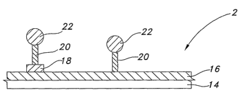
Referring now to FIGS. 3A and 3B, a diagrammatic representation of an
embodiment
using polymeric materials linked to photoreactive moieties is shown. A surface
of a medical
-22-
CA 02578833 2007-01-22
WO 2006/019848 PCT/US2005/024903
device 14 serves as a substrate for a layer of polymeric materia116. A
photoreactive linker
20 attaches to the polymeric material 16 either directly or via a reactive
group 18. In this
embodiment, the free end of the linker includes a photoreactive moiety 20
which is bound to
a therapeutic agent 22. As shown in FIG. 3B, upon exposure to an applied
energy source 24,
the therapeutic agent 22 is released from the polymeric material 16.
Referring now to FIGS. 3C to 3D, a schematic representation of an alternative
embodiment of the invention is shown. In this embodiment, a surface of a
medical device 14
serves as a substrate for a layer of polymeric materia116'. The layer 16'
includes two
miscible polymeric materials labeled polymer A and polymer B. In this
embodiment,
polyiner A includes a photoreactive moiety 20. Polymer B includes a
therapeutic agent 22
bound to a linker 28 in the vicinity of photoreactive moiety 20. Upon exposure
to an applied
energy source 24, the photoreactive moiety 20 reacts with the linker 28 to
release the
therapeutic agent 22 from Polymer B.
In a still further aspect of the present invention, light reactive drug is
contained in
polymeric micelles. The micelles may be added as a layer between a medical
device
substrate and a polymeric matrix or may be integrated into a polymeric coating
on the
substrate or may be added as a layer on a polymeric coating on the su.bstrate.
Referi in.g now to FIGS. 4A and 4B, a schematic representation of yet a
further
embodiment is shown. In this embodiment, a surface of a medical device 14 is
coated with a
polymeric materia116". The material 16" is embedded and/or coated with
micelles 22
having therapeutic agent 26 contained therein. Upon exposure to an appropriate
applied
energy source 24 the micelle 22 expands or opens so as to release the
therapeutic agent 26
held therein. Preferably, the therapeutic agent is also photoreactive or
derivatized to be
photoreactive.
Suitable Therapeutic Agents
Both water-soluble and water-insoluble therapeutic agents will find use in the
coatings covered by the invention. For purposes for this application, the
terms water-soluble
and water-insoluble therapeutic agent will have the following definitions.
Water-soluble
therapeutic agent will mean that up to 30 parts of solvent are required to
completely dissolve
- 23 -
CA 02578833 2007-01-22
WO 2006/019848 PCT/US2005/024903
one part of therapeutic agent. The term water-insoluble therapeutic agent will
mean greater
than 30 parts of solvent are required to dissolve one part of the therapeutic
agent. For further
discussion of these terms, see U.S. Pharmacopia, National Formulary, latest
edition,
incorporated herein by reference.
Examples of suitable therapeutic agents include, without limitation, thrombo-
resistant
agents, anti-microbial agents, anti-tumor agents, anti-viral agents, cell
cycle regulating
agents, their homologs, derivatives, fragments, pharmaceutical salts, and
combinations
thereof. Preferably, the therapeutic agent is an antimicrobial agent. More
preferably, the
therapeutic agent is photoreactive or derivatized to contain a photoreactive
moiety.
Useful anti-thrombogenic agents may include, for example, heparin, heparin
sulfate,
hirudin, chondroitin sulfate, dermatan sulfate, keratin sulfate, lytic agents,
including
urokinase and streptokinase, their homologs, analogs, fragments, derivatives
and
pharmaceutical salts thereof.
Useful antimicrobial agents may include, for example, penicillins,
cephalosporins,
vancomycins, aminoglycosides, quinolones, polymyxins, erythromycins,
tetracyclines,
chloramphenicols, clindamycins, lincomycins, sulfonamides, their homologs,
analogs,
fragments, derivatives, pharmaceutical salts and mixtures thereof.
Useful anti-tumor agents may include, for example, paclitaxel, docetaxel,
alkylating
agents including mechlorethamine, chlorambucil, cyclophosphamide, melphalan
and
ifosfamide; antimetabolites including methotrexate, 6-mercaptopurine, 5-
fluorouracil and
cytarabine; plant alkaloids including vinblastine, vincristine and etoposide;
antibiotics
including doxorubicin, daunomycin, bleomycin, and mitomycin; nitrosureas
including
carmustine and lomustine; inorganic ions including cisplatin; biological
response modifiers
including interferon; enzymes including asparaginase; and hormones including
tamoxifen and
flutamide; their homologs, analogs, fragments, derivatives, pharmaceutical
salts and mixtures
thereof.
Useful anti-viral agents may include, for example, amantadines, rimantadines,
ribavirins, idoxuridines, vidarabines, trifluridines, acyclovirs,
ganciclovirs, zidovudines,
-24-
CA 02578833 2007-01-22
WO 2006/019848 PCT/US2005/024903
foscarnets, interferons, their homologs, analogs, fragments, derivatives,
pharmaceutical salts
and mixtures thereof.
While the foregoing therapeutic agents have been used to prevent or treat
various
conditions, they are provided by way of example and are not meant to be
limiting, as other
therapeutic agents may be developed which are equally applicable for use with
the present
invention.
The rate of release of the therapeutic agent will be controlled by the
intensity,
frequency and duration of ultrasound energy or light energy to which the
polymeric structure
containing the therapeutic agent is exposed. The rate of release will also be
controlled by the
area of the medical device exposed to the energy. A principle limitation upon
the therapeutic
agent is that it neither be degraded nor rendered substantially inactive while
being loaded into
the polymeric coating or being exposed to the applied ultrasound or light
energy source.
Furthennore, the therapeutic agent should not react witlz the polymeric
material in which it is
contained. Generally, the amount of therapeutic agent present in a coating of
the invention
will be greater than the standard single dose for the therapeutic agent to be
administered
preferably orders of magnitude greater than the standard single dose.
Proportions of the
therapeutic agent that are suitable for the purposes of the invention range
generally from
about 0.1 to about 70 parts by weight of the coating, with the balance being
the polymeric
component.
Methods of Making and Using Coatings
The coating is prepared according to the invention by dissolving the polymeric
material in a solvent to form a first and combining this first solution with a
solution or
suspension containing a the therapeutic agent. Preferably, these may be
combined at room
temperature or at a slightly elevated temperature with the aid of agitation.
It is preferred to
employ solvents which readily evaporate from the coating at room temperature,
or at an
elevated temperature below that which inactivates the therapeutic agent.
Where the therapeutic agent used is insoluble in the dissolved polymer
material, it is
preferred that the agent be very finely subdivided, as by grinding with a
mortar and pestle. A
-25-
CA 02578833 2007-01-22
WO 2006/019848 PCT/US2005/024903
preferred form. is micronized, e.g., a powder wherein all particles are of a
size of 5 microns or
less.
The coating may be preferred by first dissolving the polymeric material such
as a
biomedical polyurethane in a solvent. The therapeutic agent is then dissolved
in the same or
a different solvent. Solvents used in making the coating will depend upon the
specific
polymeric material and therapeutic agent or combination of agents. For
example, useful
solvents include acetic acid, methyl acelate, ethyl acetate, hexane, N-N
dimethylacetamide
(DMAC), tehahydrofuram (THF), alcohols, water, N-methyl pyrrolidone (NMP) or N-
ethyl
pyrrolidone (NEP) and combinations thereof.
Certain desired solvents for the polymeric material may not be good solvents
for a
therapeutic agent of choice. In this case, a solvent is selected which will
dissolve the
therapeutic agent and be miscible with the solvent for the polymeric material.
Thus, a solvent
solution of the therapeutic agent may be combined with a polymeric material in
solution, and
the two solutions may then be combined to form a uniform mixture.
A polymeric matrix may be formed by admixing powdered polymer and therapeutic
agents together and melting the mixture to a liquid form which can then be
applied by dip
coating to the medical device.
Alternatively, a polymeric matrix may be admixed with an appropriate solvent
to
form a solution. The therapeutic agent may then be added to the solution which
can then be
applied to the medical device using conventional methods such as dip coating
or spray
coating. The solvent may be driven off in a drying process, leaving behind the
polymeric
coating.
In one aspect of the invention, the polymers are bloclc polymers formed into
circular
micelles. See, for example, Kim et al., J. of Controlled Release, 65(3), 345-
358 (2000). The
micelles so formed are large enough to accommodate therapeutic agents. Once
formed, the
micelles are loaded with the agent using a known dialysis method. See, for
example, Kwon,
et al., J. Controlled Release, 29, 17-23 (1994). Afterwards, the solution may
be treated so as
to remove unloaded drug and aggregated particles, for example using
centrifugation. The
-26-
CA 02578833 2007-01-22
WO 2006/019848 PCT/US2005/024903
micelles so formed may be freeze dried for storage or mixed with a solvent or
formed into a
hydrogel or polyamine matrix for application onto the TIVAD, either alone or
associated
fixrther with a polymeric matrix as described previously.
Accordingly, in an alternate embodiment, circular micelles surrounding a
therapeutic
agent are added to a polymeric material and the mixture applied as a coating
onto the medical
device. A diagrammatic representation of this embodiment is shown in FIGS. 4A
and 4B.
The medical device 14 includes a polymeric material 16 including mycelles 26
containing
therapeutic agent 22. The mycelles 26 are shown evenly distributed in the
polymeric material
16, where they may be trapped in pore structures, captured in enlarged
polymeric chains, or
residing at the surface of the polymeric material 16. Upon application of an
energy source 24
as shown in FIG. 4B, the myselles release the therapeutic agent therefrom.
An iraplantable medical device may be coated with the polymeric coating of the
invention and implanted into a patient in need thereof. Suitable coating
methods will depend
upon the particular polymeric material used, and will be apparent to one
having ordinary skill
in the art. Conventional coating methods such as dip coating, spray coating or
dip casting
may be used.
Use of the Medical Devices of the Invention
Once implanted, the medical device is subjected to an energy source to
increase the
therapeutic agent kinetics and/or degrade the polymer so as to release the
therapeutic agent
contained therein. The energy required to control the rate and duration of
release of the
therapeutic agent can readily be adjusted.
The optimal energy for producing a safe and effective dosage will depend on
the
particular polymeric structure and therapeutic agent used. In order to assure
safe levels of
release of the therapeutic agent, it is possible to test the implant in a
liquid medium designed
to mimic the in vivo environment and observe the rate of release of the
therapeutic agent upon
exposure to known levels of energy. In this way, a curve of applied energy
versus therapeutic
agent release rate can be derived. The coating can be made to deliver a
predetermined rate of
release of the therapeutic agent by selection of an appropriate intensity and
duration of
applied energy, based on the curve.
-27-
CA 02578833 2007-01-22
WO 2006/019848 PCT/US2005/024903
It is possible to use different photoreactive polymers with different
therapeutic agents,
so that exposure to a first light energy source will release a first
therapeutic agent while
exposure to a second (i.e., different frequency) light energy source will only
release a second
therapeutic agent. Similarly, it is possible to use different polymer coatings
having different
therapeutic agents contained therein, so that exposure to a light energy
source will only
release a first therapeutic agent while exposure to an ultrasound energy
source will release a
second therapeutic agent.
For exposure of the medical device to ultrasonic energy, a conimercially
available
ultrasonic transducer may be used by placement of the ultrasound device on a
surface of the
skin over the implanted device. Desirably, a coupling media is placed between
the ultrasound
device and tliL skin to improve conveyance of the ultrasound energy. Suitable
coupling
agents are known to those in the art.
For exposure of the implanted medical device to light energy, a ligllt source
emitting
the appropriate wavelength of light including a probe for intradermal
insertion may be used.
Such probes are disclosed, for example, in U.S. Patent No. 6,620,154 to
Amirkhanian et al.
The probe may be used to administer laser treatment to a surface of an
implanted medical
device by insertion intradermally either directly above the medical device or
inside the
medical device.
Example 1- Ultrasound Activatable Micelles
This example describes a coating made with a cross-linked polymeric material
formed into micelles loaded with therapeutic agent that will release the agent
upon exposure
to ultrasound energy. An amphiphylic alternating copolymer consisting of
poly(ethyleneglycol) and poly(L-lactic acid) as shown below is used to form
micelles. The
polymeric micelles are further stabilized by polymerization using N,N-
diethylacrylamide in a
poly(L-lactic acid) inner core of the micelles. The micelles are fixri:her
optimized by reaction
of acetylated hydroxyalkyl carboxylic acid derivatives to add functional
groups, such as -
COOH, S04,H, NH or the like, as attachment sites for the therapeutic agent.
-28-
CA 02578833 2007-01-22
WO 2006/019848 PCT/US2005/024903
O f/CH2 11
C O /C HZ\ CH2\ /O \ O
CHZ O CH2 CH2 O
x Y CH3 x
CH3
PLA-PEG-PLA triblock copolymer
The hydrophilic/hydrophobic copolymer is dissolved in methylene chloride and
emulsified with a 5% aqueous solution of albumin containing an antibiotic
and/or a
thrombogenic agent by sonicating for 2 minutes, and spray-drying to produce
particles (10
m). The micelle hydrogel microparticles are redissolved in an aqueous solution
of sodium
chloride. The polymeric micelle composition is dip coated and/or spray coated
onto an inner
surface, outer surface or both of the TIVAP to form the coated medical device.
Release of
the therapeutic agent is accomplished by the application of ultrasound energy
on the surface
of the skin over the implant. The ultrasound energy is in the frequency range
of from about
KHz to about 90 KHz for from about 0.1 seconds to about 20 seconds. The
therapeutic
agent is released from the core of the micelles and available to the
surrounding tissue.
15 Example 2 - Ultrasound Activatable Micelles
This example describes a coating made with a cross-linked polymeric material
which
forms micelles loaded with therapeutic agent that will release the agent upon
exposure to
ultrasound energy. Poly(ethylene oxide glycol)/poly(propylene oxide glycol)
copolymers and
poly(C-capriolactone) are used to form a block polymer as shown below.
iH3 O
CH2 O X CH2 O O
CH2 CH2 O ~CH2 (CH2)5 O
x y x z
PEG/PEP/PEG/PCL
The core of this polymeric micelle is stabilized by forming an
interpenetrating cross-linked
system using N,N,d.iethylacrylamide as a cross-linking agent. The therapeutic
agent is
incorporated into the micelle as described above. The micelle is dried and
used directly as a
-29-
CA 02578833 2007-01-22
WO 2006/019848 PCT/US2005/024903
coating on a medical device substrate or is dried and applied onto a polymeric
coating on the
substrate.
Example 3- Ultrasound Activatable Micelles
This example describes a coating made with a cross-linked polymeric material
which
forms micelles loaded with therapeutic agent that will release the agent upon
exposure to
ultrasound energy. A commercially available poly(ethylene/glycol)-
poly(propylene glycol)
triblock copolymer (PEO-PPO-PEO), as shown below is used to make the polymeric
material
of the coating. The copolymer is optionally cross-linked to form an
interpenetrating network.
C) H3
CH2~ O
CH2 CH2 O
x y
To a commercial polymer, (PLURONIC 105 or PLURONIC 127, available from BASF
Corp., Ludwigshafen, Germany) is added N,N-diethylacrylamide to stabilize the
hydrophobic
core of the micelle. The therapeutic agent is incorporated into the micelle as
described
above. The micelles are dried and used directly as a coating on a medical
device substrate or
are dried and applied onto a polymeric coating on the substrate.
Examnle 4- Light Activatable Coating
This example describes a coating made with a polymeric material including
therapeutic agent which is attached by light reactive pendant chains to a
surface of a medical
device, wherein the coating will release the agent upon exposure to light
energy. A water
soluble copolymer of N-(2-hydroxypropyl) methacrylamide and a photoreactive
oligopeptide
containing a therapeutic agent are provided as shown below.
-30-
CA 02578833 2007-01-22
WO 2006/019848 PCT/US2005/024903
I H CH2 polymer backbone precurser
n or polymer backbone
C O
I H linker
CI H2
HC O therapeutic agent may add optional
I photoreactive moiety
CH3
A solution of the water-soluble copolymer is applied to at lease one of the
inside and
outside surfaces of the TIVAD. Release of the therapeutic agent is
accomplished by the
application of 650 mu wavelength light to the TIVAD for 60 seconds, to the
surface of the
skin surface over the implant. The light penetrates the skin to activate
release of the drug
from the oligopeptide. Alternatively, a light probe is inserted into the port
via the septum to
introduce light directly into the reservoir of the port. The release rate is a
function of the light
exposure time.
It will be apparent that the present invention has been described herein with
reference
to certain preferred or exemplary embodiments. The preferred or exemplary
embodiments
described herein may be modified, changed, added to, or deviated from without
departing
from the intent, spirit and scope of the present invention, and it is intended
that all such
additions, modifications, amendments and/or deviations be included within the
scope of the
following claims.
All publications, patents, and patent applications referenced in this
specification are
incorporated herein by reference to the same extent as if each individual
publication, patent,
or application had been specifically and individually indicated to be
incorporated herein by
reference.
-31-