Note: Descriptions are shown in the official language in which they were submitted.
CA 02579300 2007-03-06
METHOD FOR PRODUCING A COATED BASIC MATERIAL FOR A HYDRAULIC
COMPOSITION, COATED BASIC MATERIAL FOR A HYDRAULIC COMPOSITION,
ADDITIVE FOR A HYDRAULIC COMPOSITION AND METHOD FOR PRODUCING
A HYDRAULIC COMPOSITION
The Technical Domain
The present invention relates to a method for producing a coated basic
material for a hydraulic
composition in conjunction with the preamble of the first claim. The present
invention relates
furthermore to a coated basic material for a hydraulic composition, additives
for a hydraulic
composition and method for the production of a hydraulic composition in
accordance with the
preambles of the other independent claims.
The State of the Art
Cement, a raw material, is, as a general rule, obtained from cement clinker.
This process
requires that cement clinker, which is the starting product issuing from the
rotational cement
kiln, be ground into pulverized cement and then mixed together with gypsum,
which acts as a
curing regulator, whereby cement results from the mixing process. The cement
is stored in silos
following manufacture. If the cement is to be further transformed into
concrete, the raw material
cement is commingled with additional materials and chemical. For example, the
cement can be
mixed together with water, stone and other additives inside a mechanical
mixer, which is, for the
most part, computer controlled. The addition of fluid or pulverous additives
is aimed at
1
CA 02579300 2007-03-06
improving the chemical and/or physical characteristics of the fresh and/or
cured cement. Thus,
for example, the additives are capable of influencing flow behaviour,
viscosity and compression
behaviour, as well as the curing behaviour of the concrete.
Representation of the Invention
Competition in the field of chemical additives results in both improved and
streamlined process
technologies and in product improvements. Additionally, such competition
should lead to the
enhancement of concrete properties as well as further improvement in the
workability of
concrete.
The object of the present invention is, therefore, the creation of a method
for producing a coated
basic material for a hydraulic composition, a coated basic material for the
production of concrete,
an additive for the production of concrete and methods for the production of a
hydraulic
composition the result of which, being a simplified process technology and/or
increased concrete
quality.
It is proposed that these objectives be satisfied by means of the
distinguishing features of the
independent claims.
The essence of the invention is thus that prior to mixing of the hydraulic
composition, the basic
material is at least partially coated with an additive, more specifically, the
additive is at least
partially arranged on a basic material for the production of concrete.
2
CA 02579300 2007-03-06
One of the advantages of the invention is that the properties of the concrete
can be significantly
improved if, prior to the mixing of the individual concrete components, at
least some of such
individual components are coated.
This procedure can, for example, in the case of the particles of the basic
material cement permit
the physical and chemical properties to be modified prior to mixing and the
chemical reaction
with the other basic materials can be influenced during the mixing process.
For example, a non-
exhaustive list of additives whose names for the most part reflect their
function are as follows:
concrete fluidizers; flow agents; aerants; retardants; accelerants;
stabilizers; chromatic reducers;
embedding assisters; foamants; sealants; recycling assisters and corrosion
inhibitors. If, for
example, the cement prior to mixing with the other basic materials is coated
with a concrete
fluidizer, the ability of the coated cement to absorb water as compared to the
untreated cement
can be positively influenced.
It should be stressed from the outset that it is possible to coat all of the
materials that are
employed in the production of concrete. The particles can be most
advantageously coated if the
material particles are conveyed pneumatically and/or by gravity. This implies
that the coating
process need not necessarily take place while the concrete is being
manufactured. The basic
materials can therefore be pre-coated at the place of their production. Thus,
for example, cement
particles can be coated immediately following the cement production process.
Included in another subgroup of the basic materials can be materials or
additives such as, for
example, silica fume, fly ash, light aggregate, slag, foundry sand, fibrous
materials, which can
include organic materials such as polypropylene fibres etc. or inorganic
fibres such as basalt,
3
CA 02579300 2007-03-06
glass, etc. For example, fly ash, having different origins, possesses varying
adsorption
characteristics and thus, depending on the origin thereof, features a wide
range of properties
when added to concrete. If additives are used for coating, the characteristics
are identical and
more adapted to the environment so that varying material origins do not have
to be taken into
consideration.
Alternatively, or as a supplement to the coating of a subgroup of basic
material, it can also be
advantageous if, prior to mixing, particles belonging to two or more subgroups
are coated with at
least one additive. This procedure greatly strengthens the bond between the
coated input
materials and the cement paste. This has a positive effect on the resistance
to de-icing salt, and
the durability of the concrete. In addition, there results a positive
influence on the rheology in
respect of the rheaological characteristics of the cement, which results in
reduced mixing times
and improved compatibility with the additives.
If the additive is sprayed by means of a nozzle and/or a mixer into the stream
of the basic
material, it is possible to achieve an especially homogeneous and uniform
mixing of the
particles. Use of the nozzles and/or mixers also ensure that, depending on the
dimensions of the
nozzle and mixer, it is possible to select a particularly high relative speed
between coating agent
and particle and thus raise the adsorption capacity of the coating agent.
Listed by way of
example are a number of suitable pneumatic nozzles and/or mechanical mixers;
jet mixers with
a Laval nozzle; jet mixer with a Venturi pipe; jet mixer with a propeller
mixer; jet pump and
various vortex mixers. An example of a mechanical mixer is the rotation mixer
with screw and
the drum mixer.
4
CA 02579300 2007-03-06
The additive can be sprayed into the stream of basic material either in the
direction of flow
and/or opposite to the direction of flow. If, for example, the spray angle can
be varied, the
collision speed and the relative speed of coating material and particles to be
coated can be
regulated.
It is useful if the additive is at least partly added in fluid form. For
example, the fluid additive
can be atomized (aerosol) and/or broken up into droplets (droplets) and/or
converted into vapour (vapour). The thickness of the coat can be regulated by
varying the consistency.
The fluid additive can be mixed together with a solvent, which is preferably
water, and then
added, whereby such solvent evaporates following addition.
The energy required for evaporation can be drawn from the cement or be
supplied by other
means. The injection spraying and the atomization of additives with air is
particularly useful if
the cement is to be transferred via a pneumatic transfer pipe into the
mechanical mixer. If the
fluid additive is to be sprayed into the material in the direction of material
flow; as is the case in
so-called jet washers, which are employed in the scrubbing of dust-laden waste
gases, it is
possible to nullify both the agglomeration effect of cement particles on
additive droplets as well
as the precipitation effect. The air in which the cement is transported can be
controlled for
temperature and moisture content. Temperatures in the region of 10 C are
sufficient to evaporate
the solvent of the additive. This has the desired effect that the additive and
the cement do not yet
react since the water was drawn off with the pneumatic air that was used to
transport the cement.
The collision of additive droplets and cement particles results not only in
the coating of the
particles, but also the fine distribution of dust-like additives inside a
pneumatic cement air
5
CA 02579300 2007-03-06
transport pipe results in the homogeneous mixture of both chemical co-
reactants. Particularly
advantageous in this regard are air transport channels employing pneumatic
gravimetric feed.
It has also been demonstrated that it is important to precisely plan for the
amount of energy that
will be required to evaporate the solvent or water. The temperature of the air
used to transport
the cement particles should be high enough to absorb the latent heat of
evaporation and in any
case any additional solvent heat from the fluid additive that may be present
while preventing the
transport air from becoming saturated and provoking vapour condensation (water
steam
condensation). The relative humidity of the air in which the cement particles
are transported
should be sufficiently low or regulated to such an extent that following
absorption of the
evaporated solvent, in particular, water, local oversaturation does not occur
in the lower parts of
the mixing apparatus or the transport conduit, which can lead to steam
condensation. The heat
required to evaporate the solvent, in particular, water, can be drawn from the
cement since the
latter exhibits sufficiently high excess temperature or appreciable heat.
The fluid additive can also be directly added in melted form in which case the
melted material is
added inside a mixer to the material to be coated, which involves such
material being coated
during the mixing process or, for example, the material to be coated is caused
to pass through the
melted material and stiffens after passing through the melted material. The
thickness of the
additive layer thus applied can be regulated by adjusting the various
parameters such as passage
time of the melted material, cooling rate, mixing time, etc.
6
CA 02579300 2007-03-06
Such an application process is particularly advantageous when used to coat
fibres, which can be
drawn through the melted material following which the fibres can be further
treated after the
additive has stiffened.
The additive can also be added, at least partly, in powdered form. This method
permits the
addition of additives that cannot be added in fluid form.
At least at the point of injection spraying, there should be produced a
turbulent stream of basic
material and/or of the sprayed-in additive.
The following are examples of additives that can be used: concrete fluidizers;
flow agents
(reaction); retardants; accelerants such as stiffening and hardening
accelerants; stabilizers, aerants and/or sealants, all of which influence the
chemical and/or physical characteristics during
the reaction of the concrete components.
It is advantageous, if employed as an additive, that a high-performance
concrete fluidizer such
as, preferably, the product ViscoCrete from the Sika company. This high-
performance
concrete fluidizer reduces the water requirement of the cement and improves
the workability of the concrete. 20
All basic materials that are used for the further processing of concrete can
be employed as basic
materials to be coated. As has been mentioned above, the proposed coating
process is tied
neither locally nor temporally to the concrete production process, an
advantage that enables
coating to be carried out at the place of production while the basic materials
are being produced.
7
CA 02579300 2007-03-06
For example, pneumatic nozzles and/or mechanical mixers installed inside the
conveyance
conduits or storage locations for the basic materials can facilitate adequate
coating of the basic
materials.
Overview of the Drawings
Embodiments of the invention will next be described in greater detail with the
aid of drawings.
The same elements are referenced in the various figures with the same
reference numerals. Both
the flow direction and the flow speed of the media are indicated by means of
arrows.
Shown are:
Fig. 1 Prior art concrete mixing process in a concrete plant;
Fig. 2 Schematic representation of the concrete mixing process;
Fig. 3 Cement particles and molecules of a concrete fluidizer prior to
adsorption;
Fig. 4 Two cement particles with adsorbed concrete fluidizer molecules;
Fig. 5 Schematic representation of one embodiment of the proposed concrete
mixing process;
Fig. 6 Further embodiments of the proposed concrete mixing process;
Fig. 7 A section through the system for producing cement as well as cement
silos;
Fig. 8 Section through a uniflow mixer;
Fig. 9 Section through an opposite stream mixer;
Fig. 10 Section through a vortex mixer with rotational atomizer;
Fig. 11 Schematic representation of a proposed coating device;
Fig. 12A Schematic representation of a further proposed coating device;
Fig. 12B Representation of the further proposed coating device;
8
CA 02579300 2007-03-06
Fig. 13A A comparison of the durability of coating at 25 C using the device in
accordance with Fig. 11;
Fig. 13B A comparison of the durability of coating at 80 C using the device in
accordance with
Fig. 11;
Fig. 14 A comparison of the durabilities of coating at 80 C using the device
in accordance
with Fig. 11;
Fig. 15 Comparison of the durabilities of coating before and after milling;
Fig. 16 Comparison of the durabilities of coating before and after milling;
In the interest of clarity, only the essential elements of the invention have
been shown.
Embodiments of the Invention
Figure 1 shows the prior art concrete mixing process used in concrete
production as
conventionally implemented in concrete plant 1. Shown to the left in Figure 1
is device 2 for the
measured dispensing of stone. In this embodiment, this device comprises four
funnel-shaped
containers 3, each of which features at its lower opening region a conveyor
belt 9 serving to
transport the stone to mechanical mixer 8. The transport or running direction
of conveyor belt 9
is indicated by means of arrows referenced with the reference numeral 10.
Depending on the
type of concrete to be produced, the sieve size of the stone is approximately
between 0mm and
16mm in diameter. The stone can be sorted according to size and stored in the
four containers 3.
The cement, which constitutes the binding agent for the concrete, and which
exhibits a particle
size in the region of approximately 1 to 100 micrometers, is stored in cement
silo 4. The cement
is then also conveyed to the mechanical mixer 8 via conveying units 5, which,
for example, can
9
CA 02579300 2007-03-06
be motor-driven screw drives. A measured quantity of cement is waiting in
container scale 6.
Also located at mixer 8 the feed conduit 7 for water and additives, which can,
for example, be
concrete fluidizer, flow agent, aerants, retardant and similar agents, and
which are added during
the mixing process. Inside mechanical mixer 8, which is represented in this
case as a continuous
mixer with a horizontal stirring apparatus, the stone, water, cement and
additive are added to a
finished concrete mixture 11. Finished concrete 11 is conveyed via a conveyor
belt 9 to
transport vehicles 12.
In Figure 2, the mixing process employed in the production of concrete is once
more shown in
schematic and simplified fashion. Shown in the upper portion of Figure 2 are
the four boxes
representing the input components for concrete, namely additives 13, basic
material 14, 16 which
is subdivided into subgroups 14, e.g. sand and/or stone and/or etc. and
subgroup 16, more
particularly, the hydraulic binding agent, in this case, cement and water 15.
The foregoing input
components are blended together in a mechanical mixing process inside mixer 8
in order to
produce prepared concrete mixture 11. The chemical and physical properties of
the concrete
mixture in such a mixing process are chiefly influenced by the proportions in
which the concrete
components are mixed together. It is proposed, that in accordance with the
invention, through
treatment of one or a plurality of concrete input components, prior to the
mixing process, both
the properties of such input components and the properties of the prepared
concrete mixture 11
can be modified.
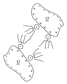
Figures 3 and 4 show the coating of particles at the molecular level.
CA 02579300 2007-03-06
Shown in the upper portion of Figure 3 is a cement particle 17 approximately 0
to 100
micrometers in size. Cement particle 17 exhibits both positive 18 and negative
charge carriers
that are indicated by means of a "+" and a "-" (minus sign). Shown in the
lower portion of
Figure 3 is a molecule of an additive, in this case, a concrete fluidizer and
in this example a
polycarboxylate molecule. The polycarboxylate molecule consists of a main
chain with negative
excess of charge and neutral side chains 21. If the concrete fluidizer with
its molecules has
already been added to the cement prior to the mixing process in mixer 8, then
the cement, or,
rather, its cement particle 17, can be coated on the surface.
In Figure 4 the "effect" of concrete fluidization is shown in greater detail.
The molecules 20 of
the concrete fluidizer are adsorbed onto the surface of cement particle 17 due
to the electrical
attraction of the opposing charges + and - of the molecules. In this
arrangement, the negative
charge 19 of the main chain of molecule 20 is attracted to the positive charge
18 of the cement
particle 17 and molecule 20 becomes completely bonded to a cement particle 17.
The extended
side chains 21 of the bonded molecules 20 act as spacers between the cement
particle 17. This
arrangement acts to prevent cement particle 17 from agglomerating or forming
lumps. Such prevention of reaction/binding of cement particle 17 one to
another is known by the term "steric
effect". Such surface coating of the cement particles and therefore also of
the binding agent of
the concrete, influences positively the consistency of the input materials for
the concrete. The
capacity of the concrete to absorb water is positively influenced by means of
the coated cement,
in addition, the overall workability of the concrete is improved.
Each of Figures 5 and 6 is a schematic representation, which more completely
elucidate the
novel method for producing cement with an integrated coating procedure. Shown
in the upper
11
CA 02579300 2007-03-06
portion of Figure 5 are the four boxes representing the input components for
the concrete, more
particularly: additives 13; first basic material 14; second basic material 16;
and water 15. In this practical application, additive 13, which, in this case,
is a concrete fluidizer, for example,
ViscoCrete" from the Sika company. It will, of course, be appreciated that
other types of
additives, or a combination thereof, can be added such as those that have been
described above.
In this embodiment, the first basic material 14 is stone. The second basic
material 16, which is
cement, acts as a binding agent for the concrete. Water 15 is an additional
fluid component that
is mixed with concrete fluidizer 13. These input components are mixed together
in a mechanical
mixing procedure inside mixer 8 to form prepared concrete mixture 11. This
mixing process
alone ensures that the chemical and physical properties of the concrete
mixture will be
influenced primarily by the mixing parameters and the ratios in which the
materials are added to
the mix. In the proposed process, cement 16 is coated with concrete fluidizer
before the
mechanical mixing procedure takes place inside mixer 8. This takes place in
Figure 5, under
reference numeral 22, particle coating. Particle coating 22 comprises that
fluid concrete fluidizer
13 be added to cement 16. Preferably, the fluid droplets of concrete fluidizer
13 should exhibit a
high velocity relative to the cement particles 16. The high relative velocity
enables collisions
between the particles and an attendant surface coating of the cement 16, a
process also described
in Figures 3 and 4 and in the figure description appertaining thereto. It is
advantageous if a
turbulent particle flow were created, for example, by means of designing the
pipe with a suitably
shaped cross-section. For the injection spraying of the concrete fluidizer,
for example, uniflow
and counter-flow mixers can be employed.
12
CA 02579300 2007-03-06
Schematically illustrated in Figure 6 is a further embodiment of the proposed
concrete mixing
process. In contrast to Figure 5, the particles 22 of first basic material 14
of the concrete are
coated. In this example, stone is being coated. Of course, other particles,
such as especially
aggregate such as e.g. silica fume, fly ash, light aggregate, slag, fibrous
materials, which are to
be added to the concrete, can be coated with an additive before the concrete
is worked.
Figure 7 shows a section of cement plant 23 and cement silos 4. Shown in the
left hand region
of the drawing is the area of the plant reserved for producing cement 23,
wherein pulverized
cement is milled together with gypsum. The newly-mixed cement is conveyed via
conveyance
units 5 to the four cement silos 4 shown in the right hand portion of the
drawing and stored
therein pending use. The conveyance of the cement is, as shown in Figure 1,
effected by means
of conveyance units which may, for example, involve the transport of cement
via conduits using
compressed air. Indicated in Figure 7 are two locations at which particle
coating 22 of the
cement can potentially take place. First of all, the objective of the
invention is more readily 15 attained if the cement is coated while transiting
the conduits of the conveyance units 5. Further
in this regard, Figures 8 and 9 illustrate examples of two possible mixing
arrangements, each of
which is shown in sectional view. As an alternative to, or as a supplement to
this arrangement,
particle coating 22 can take place inside cement silo 4. To illustrate this
arrangement, Figure 10
shows an example of a suitable mixer.
Figure 8 shows a section through a uniflow mixer 24. Arrow 26 indicates the
direction in which
the cement particles flow through uniflow mixer 24. In this example, uniflow
mixer 24
comprises an angled pipe section wherein cross-sectional constrictions 25 have
been made inside
the lower angled pipe section. Such cross-sectional constrictions 25 act to
increase the velocity
13
CA 02579300 2007-03-06
of the cement particles (continuity equation of hydrodynamics). In the region
of cross-sectional
constriction 25, concrete fluidizer 13 is sprayed through a nozzle 28 and
mixed with the cement.
In the region of the cross-sectional constriction, optimal swirling of the
cement particles and of
the particulate of concrete fluidizer 3 takes place. Nozzle 28 can be
positioned at various angles
relative to flow direction 26 of the cement particles.
Figure 9 shows a section through counter-flow mixer 27. In contrast to uniflow
mixer 24
ofFigure 8, nozzle 28 is arranged so as to spray material against the
direction 26 in which the
cement particles flow. The particles of concrete fluidizer 13 collide with the
cement particles,
which benefits optional surface coating of the cement particles.
Figure 10 shows a sectional view of a vortex particle mixer 29 fitted with
rotational atomizer
inside a cement silo 4. Cement particles are introduced through the upper
opening and arrow 26 indicates the direction in which the cement particles
flow. Left-hand arrow 13 indicates the
supply of additive, which can, for example, be a concrete fluidizer. The
cement particles fall
onto a product distribution cone and so are radially distributed and
gravitationally precipitated
downwardly. In this arrangement, the cement particles are sprayed with
droplets of fluid that
have been produced in a rotational atomizer.
It has been demonstrated that coating with additives of organic or inorganic
fibres, especially of
mineral fibres, can be accomplished if such fibres come into direct contact
with the additive.
Advantageously, this coating procedure involves causing the additive to enter
a fluid phase and
drawing the fibres through such fluid phase, or, alternatively, by applying
such fluid phase to the
fibres by means of rolling. The fluid phase can, for this purpose, be achieved
by adding solvents,
14
CA 02579300 2007-03-06
in particular water, or by melting the additive. Should melted additive be
employed, the fibres
used should exhibit suitable physical characteristics so that they do not
sustain damage during
the coating process, e.g. they do not melt. Mineral fibres, especially basalt
fibres, have shown
themselves to be advantageous when employed in such arrangements. Addition of
such fibres to
a hydraulic composition can, for example, influence the shrinkage, the
stability and behaviour
when exposed to heat, etc.
Embodiment example:
Basalt fibres, such as can be obtained from Basaltex, Belgium, were to be
coated with a
fluidizing agent. The basalt fibres exhibited an average diameter of between
12 and 15 . The
high-performance concrete fluidizer employed was ViscoCrete from the Sika
company.
Immediately after it had been produced, the fluidizer in fluid phase was
transferred into a heated
tub, an alternative to which would be melting the fluidizer inside the tub.
Next, the basalt fibres were drawn through the molten mass present inside the
tub. The fibres, now coated with
fluidizer, were then allowed to cool down in air, and the coated fibres were
then transferred to a
cutting device to be cut into 6 mm, 12 mm or 25 mm lengths. The coat can also
be cooled down
inside a cooling chamber, which greatly reduces the cooling-down period. The
fibre sections
were then added to a conventional concrete mixture comprising Portland cement,
whereby the
separation of the fluidizer from the surface of the fibres produced a
fluidized concrete, which lent
itself formidably to working. The coated fibres became very homogeneously
distributed
throughout the concrete mixture, without the formation of fibre bundles. This
type of cement is
eminently suited for use in large-surface flatwork, since on the one hand, the
fluidization has
made the concrete highly susceptible to flowing while on the other, the
presence of the fibres
ensures that practically no shrinkage will result.
CA 02579300 2007-03-06
High-performance concrete fluidizers and flow agents such as the product
ViscoCrete can
comprise polycarboxylates. By polycarboxylates is meant comb-shaped polymers,
which are
formed from a main chain, to which are attached carbonic acid groups in the
form of free acids
or the salts thereof, and side chains comprising polyalkyleneoxide. Such
polycarboxylates are
known in the art, e.g. from EPI 136 508 Al, EP1 138 696 H1 and EPI 138 697 Al
owned by the
applicant. The composition of the polycarboxylate is included hereunder. The
polyalkylene
oxide or polyalkylene side chains can be bonded to the main chain via ester
bonds, amide bonds,
or ether bonds. In addition to the carbonic acid groups and the polyalkylene
oxide side chains,
further functional or non-functional groups can be bonded to the main chain.
Such comb-shaped
polymers can be produced, for example, by means of copolymerization of
unsaturated mono or
di-carbonic acids with unsaturated carbonizacid esters, unsaturated carbonic
acid amides, allyl
ethers or vinyl ethers. The carbonic acids present in the comb-shaped polymers
so produced may
be present in the form of the free acids through or wholly or partially in the
form of the salts
thereof. The comb-shaped polymers can also be produced by means of polymer-
analogous
reactions. In such reactions, a polymer, comprising either latent or free
carboxlyl groups, is
reacted with one or more compounds comprising amine or hydroxyl functions
under conditions
that promote the partial amidization or, as the case may be, esterization of
the carboxyl groups.
The polyalkylene glycol of the side chain is based on polymerized epoxide -
containing
compounds, such as, for example, ethylene oxide, propylene oxide, 1-butylene
oxide, phenyl-
ethylene oxide, etc. It is preferred that the polyether side chain comprise
polyethylene oxide or
polypropylene oxide or a mixed copolymer comprising ethylene oxide and
propylene oxide and
has at its free end a hydroxyl group, a primary amino group or an alkyl group
having between 1
and 20 carbon atoms, being straight-chain, branched or cyclical, preferably a
straight chain alkyl
16
CA 02579300 2007-03-06
group having between 1 and 4 carbon atoms. Such polycarboxylates have a
molecular weight of
between 5,000 and 200,000, preferably between 8,000 and 100,000, most
preferably a molecular
weight of between 10,000 and 80,000. The carbonic acid salts can be alkali
metals or alkaline
earth metals or salts of other two or three valence electron metal ions, an
ammonia ions, organic
ammonia groups or mixtures.
In one embodiment, the proposed polycarboxylate comprises four structural
units (a, b, c and d)
and has the structural form A.
R R R R
-~H2_-C H2-C H]-{CH2_d
Ib Ic~ c~ c ==ca cD
~ I
0 {7 NH Fe
I I
1UI R1 R2
Wherein: M= hydrogen, alkali metal ion, alkaline earth metal ion, two or
three valence electron metal ion, an ammonia ion, an ammonia
group or mixtures thereof;
R = each R independent of the other hydrogen or methyl;
R'- and R2 = Cl to C20 alkyl, cycloalkyl, or alkyl aryl,
17
CA 02579300 2007-03-06
M= hydrogen, alkali metal ion, alkaline earth metal ion, two or
three valence electron metal ion, an ammonia ion, an ammonia
group or mixtures thereof;
-[AO]õ - R4,
wherein A = C2 to C4 alkylene, R4 = C, to C20 alkyl,
cyclohexyl, or alkyl aryl, and n = 2-250, preferably n = 8-200,
more preferably n = 11-150, most preferably n = 11-100;
R3 _ -NH2, -NR5R6, - OR7 NRgR9,
wherein R5 and R6 independently of each other is a C, to C20
alkyl-, cycloalky- 1 or alkyl aryl or aryl group or a
hydroxyalkyl group, such as, for example, hydroxyethyl,
hydroxypropyl-, hydroxybutyl group, or an
acetoxyethyl - (CH3-CO-O-CH2-CH2-),
hydroxyisopropyl - (HO-CH(CH3)-CH2-),
acetoxyisopropyl group (CH3-CO-O-CH(CH3)-CHZ-),
or R5 and R6 together form a ring, whereof nitrogen forms a
part, in order to constitute a morpholine or imidazoline ring,
wherein R7 is a C2 - C4 alkylene group and Rg and R9,
independently of each other, is a C, to C20 alkyl-, cycloalkyl-,
alkyl aryl- or an aryl group or a hydroxyalkyl group such as,
for example, hydroxyethyl-, hydroxypropyl-, or a hydroxy-
butyl group,
18
CA 02579300 2007-03-06
M hydrogen, alkali metal ion, alkaline earth metal ion, two or
three valence electron metal ion, an ammonia ion, an ammonia
group or mixtures thereof;
a/b/c/d = (0.1-0.9)/(0.1-0.9)/(0-0.8)/(0-0.3),
preferred (0.1-0.9)/(0.1-0.9)/(0-0.5)/(0-0.1),
more preferred (0.1-0.9)/(0.1-0.9)/(0-0.3 )/(0-0.06),
even more preferred (0.2-0.8)/(0.199-0.799)/(0.001-0.09)/(0-0.06),
especially preferred (0.2-0.8)/(0.19-0.79)/(0-0.1)/(0.01-0.3),
and a+b+c+d= 1.
The arrangement sequence of building blocks a, b, c, d can be by blocks,
alternating or random.
Polycarboxylate in accordance with Formula A can be imagined as comprising a
main chain of
polymerized units of acrylic acid and methacrylic acid or a mixed copolymer
thereof. The
polyalkylene oxide side chains are bonded to the main chain by means of ester
or amide groups.
Besides the carbonic acid groups, or, rather carbonic acid salts on the
polyalkylene side chains,
other groups can be bonded to the main chain via ester or amide bonds, such
as, for example,
alkyl groups, cycloalkyl groups, aromatic compounds, substituted aromatic
compounds,
hydroxy-alkyl groups, dialkylamino alkyl groups, or heterocyclic rings,
wherein the N of the
amide group is a component, such as, for example, morpholine or 1-midazole.
Examples of R3 groups that are bonded to the main chain via their N which is
in form of an
amide are amine radicals that comprise one or two aliphatic, cycloaliphatic or
aromatic radicals
of 1 to 20 carbon atoms such as, for example, methyl-, ethyl-, propyl-, iso-
propyl, -butyl-, iso-
19
CA 02579300 2007-03-06
butyl or cyclohexyl radicals that are independent of each other. Examples of
such amine radicals
are di-butyl amine or di-cyclohexamine. Further examples are amine radicals
with hydroxyalkyl
groups such as ethano amine or di-ethanol amine. Examples of R3 groups that
are bonded to the
main chain via their 0 as esters are aliphatic, cycloaliphatic or aromatic
radicals containing from
1-20 carbon atoms, such as, for example: methyl-, ethyl-, propyl-, iso-propyl-
, butyl-, iso-butyl-,
or cyclohexyl radicals. Other examples thereof are amino-alcohol radicals such
as methyl-
diethanolamine, triisopropazolamine, triethanolamine, dibutylamino-ethanol,
diisopropanolamine, diethylamino-ethanol, dimethylamino-ethanol.
Shown in Figure 11 is another uniflow mixer 24. The direction in which the
cement particles
flow through uniflow mixer 24 is indicated by arrow 26. The material to be
coated is loaded into
a funnel 30 and is retained inside such funnel by means of a sliding element
31. Connecting to
such funnel is an angled pipe section fitted with a nozzle 32, through which
compressed air can
be sprayed into the pipe section. Arranged in the pipe section connecting
thereto is a Prandtl-
nozzle 33 with nozzle for compressed air 34 and suction tube 35. Such suction
tube extends into
a container 36 containing coating material, in this case, concrete fluidizer
13, which is to be
mixed into the material to be coated. Compressed air is blown through nozzle
34 into the pipe
whereby negative pressure is produced inside suction tube 35, through which
fluidizer 13 is
suctioned and atomized. Nozzles 32, 33 can be arranged at various angles
relative to the flow
direction 26 of the cement particles. After the material to be coated, in this
case, cement, is
loaded into the funnel, compressed air is blown through nozzles 32 and 34 into
the pipe. Next,
sliding element 31 is opened, the cement flows through the pipe and is coated
with atomized
fluidizer 13. Next, the now-coated cement is transferred to a receptacle 37,
which is not
illustrated in greater detail. For the purposes of industrial production, the
coating process would,
CA 02579300 2007-03-06
of course, be continuous, in which case the material to be coated would be
continually conveyed,
an arrangement wherein funnel and sliding element would be obviated.
It is not necessary for the functioning of this device for it to have pipes,
but it can be readily
employed in conduits having other cross sections, in particular rectangular
cross sections. Such
conveyance conduits having rectangular cross sections are employed in cement
production,
otherwise referred to as air transfer channels or "air slides" or "fluid
slides", these serve to
transport material pneumatically and gravitationally. The cement can be
directly coated inside
such channels. This arrangement is especially advantageous if coating is to be
done immediately
prior to loading onto a means of transport such as, e.g. a truck. This
arrangement permits
individual transport means to be loaded with material having a particular type
of coating. Of
course, the type of coating process illustrated in Fig. 11 and described above
can also be
implemented in counter-flow mode as suggested in Fig. 9.
Shown in Figure 12A and 12B is a further proposed coating device 40. The
direction in which
the material to be coated, in particular, cement particles, flows through
coating device 40, is
indicated by means of arrows. The material to be coated is transferred via a
transfer line 41 into
a widening funne142, whence it falls freely in the shape of an annulus into a
collecting funnel.
The material to be coated is coated during free-fall by additive that is
applied via nozzles, in
particular Prandtl nozzles 33. The nozzles are advantageously disposed on the
outside, but can
be arranged on the inside or be arranged both on the inside and the outside.
The nozzles 33 can
be arranged at different angles relative to the direction in which the pai-
ticles to be coated are
falling. Through the appropriate positioning of the nozzles, the coating
procedure can be adapted
to the type of material to be coated. Although the Prandtl-nozzle 33 is not
shown in detail, the
21
CA 02579300 2007-03-06
functioning thereof is analogous to that of Figure 11. By using the widening
funnel to widen the
stream of particles to be coated and by selecting suitable angular positions
for nozzles 33, it is
possible to achieve uniform particle coverage. Collecting funne143 can, as
indicated, comprise a
plurality of nested funnels, an arrangement that causes the material to be
coated to be thoroughly
mixed up by whirling action, which increases the quality of the coating. The
coated material can
than be loaded directly from collecting funne143 into a transport container,
e.g. onto a truck or, as illustrated, via a conveyance device to further
transport. The conveyance device need not
necessarily feature pipes, but can be advantageously configured as air
conveyance channels, in
which conveyance takes place both pneumatically and gravitationally.
Shown in Figures 13 to 16, are rates of spread for the Portland cement that
was coated with the
aid of the device illustrated in Fig. 11 as compared to conventional methods
for infusing
additives. In each case, coating was carried out in air pressurized to 6 Bar
and 10 kg of material
were coated. Transit time for material through the device was ca. 40 sec. The
spreading rate
was determined in accordance with DIN EN 196-1.
In Figure 13A are shown the measurement results for the rate of spread of
Portland cement
coated with Sika ViscoCrete 3082 at 25 C with a dosage of 1% as related to
the weight of the
binding agent. This was compared with the results obtained from adding
ViscoCrete in fluid
form (see curve VC-3082 liq.). The measurements of the rate of spread were
carried out
immediately following coating (week 0), as well as at 4 weeks (week 4) and 12
weeks (week 12)
following coating. It is clearly apparent that the liquefying effect of the
same added quantity of
ViscoCrete when coating the cement particles is far superior to that obtained
by direct addition
of the material. Use of the coated cement particles even after 12 weeks
permitted achievement
22
CA 02579300 2007-03-06
of superior values, than was the case with direct addition. Furthermore, the
coat proved itself to
be stable.
Shown in Figure 13B are the measurement results of a Portland cement coated
with Sika
ViscoCrete 3082 at 80 C with a dosage of 1% as related to the binding agent
weight. This was
compared to the results of adding fluid ViscoCrete (curve VC-3082 liq.). Even
in this case, it is
evident that the fluidizing effect of the same dosage quantity of ViscoCrete
in coating the cement
particles is markedly superior to that achived by direct addition. Even after
12 weeks,
employment of the coated cement particles produces superior results than those
achieved by
direct addition. Even the long-term values are slightly better than those
achieved with coating at
lower temperatures, which can be explained thusly: at higher temperatures, any
water present in
the concrete is evaporated, which renders the coat more stable over extended
periods of time.
Shown in Figure 14 are the measurement results of a Portland cement that has
been coated with
Sika ViscoCrete 20HE at 80 C with a 0.5% dosage relative to the weight of
the binding agent.
This was compared to the results of adding fluid ViscoCrete (curve VC-20HE
liq.). Even in this
case, it is evident that the fluidizing effect of the same dosage quantity of
ViscoCrete following
coating of the cement particles is markedly superior than that achieved by
direct addition. Even
after 12 weeks, employment of the coated cement particles produced better
values than were
achieved by direct addition. Even after 4 weeks, employment of the coated
cement particles
yields practically the same values as those obtained immediately following
coating and markedly
better values than those obtained by direct addition.
23
CA 02579300 2007-03-06
Shown in Figure 15 are the measurement results of a Portland cement that has
been coated with
a fluidizer PC-1 of polycarboxylate with a 0.3% dosage relative to the weight
of the binding
agent (curve AM) as compared to the results of the direct addition of the
polymer (curve PC-1).
Even in this case, it is evident that the fluidizing effect of the same dosage
quantity of fluidizer
used to coat the cement particles is superior to that achieved by direct
addition. In the case of addition of material prior to cement milling, the
values mere markedly superior. The polymers
that were added prior to the cement mill are evidently at least partly
destroyed during the milling
procedure. The fluidized PC-1 used in this case comprises essentially a
polymer in accordance
with the aforementioned structural formula A, wherein:
M = H- andlor Na
R= H-
R'- = Mixture of CH3-PEG 1000- and CH3PEG3000- in a mol ratio of 50:50
R3 = HO-CH2CHZ-NH-
a/b/c/d = 0.75/0.20/0.00/0.05
Molecular weight = 26,000
Shown in Figure 16 are the measurement results of a Portland cement that has
been coated with
another RMC-1 polymer comprising substantially polycar at a 0.3% dosage
relative to the weight
of the binding agent (curve AM) as compared to the results of the addition of
fluid polymer
(curve PC-1). Even in this case, it is evident that the fluidizing effect of
the same dosage
quantity of fluidizer used to coat the cement particles is superior to that
achieved by direct
addition. In addition, the polymer RMC-1 was added prior to the milling of the
cement (Curve
BM). Even in this case, it was demonstrated that fluidizing effect of the same
dosage quantity of
24
CA 02579300 2007-03-06
fluidizer to coat the cement particles is superior to that achieved with
direct addition and that
introduction of additive prior to cement milling yielded significantly poorer
values. The fluidizer
employed in this case, RMC- 1, comprises essentially a polymer in accordance
with structural
formula A wherein:
M H- and/or Na
R = CH3-
R '= CH3-PEG 1100-
a/b/c/d = 0.50/0.50/0.00/0.00
Molecular weight = 18,000
The present invention also contemplates the application of corrosion
inhibitors on the materials
to be coated. Such corrosion inhibitors are known in the art, for example,
from EP0 635 463 Al,
EPO 941 975 Al and EPO 957 071 Al. The corrosion inhibitors disclosed in the
aforementioned
patents can be employed in accordance with the novel process described in
these presents to coat
materials, in particular cement. For coating purposes, the corrosion
inhibitors are
advantageously produced during the coating procedure itself in that the at
least partially
terminated acid/base reaction of amino compounds and acids takes place during
such procedure.
For this purpose, both substances are sprayed together into the mixture, the
result of which being
the formation of an aerosol mist in which the desired salts and compounds are
formed. The
coating is accomplished in this case with the aid of the devices illustrated
in this figure. Use of
this method results in a markedly superior coat. It is also possible, however,
for the corrosion
inhibitors to be added directly, and in any case together with a solvent.
It is advantageous for the purposes of the present invention that the products
of the at least
partially completed acid/base reactions of amino compounds and acids be
employed as corrosion
CA 02579300 2007-03-06
inhibitors. Such corrosion inhibitors can be an amino compound or mixtures of
amino
compounds, which, depending on requirements, are neutralized by means of an
acid or a
plurality of acids. Suitable amino compounds and/or amino alcohols are primary
and/or
secondary and/or tertiary amines, wherein aliphatic and/or aromatic and/or
cycloaliphatic
radicals are bonded to the nitrogen atom or wherein the nitrogen atom of the
amino compound
represents part of a heterocyclic structure and whereby one or a plurality of
amino groups are
present in the amino compound of the corrosion inhibitor. Also suitable are
amino alcohols such
as primary, secondary or tertiary aliphatic amines that comprise at least one
alkanol amine
grouping per molecule. Especially suitable amino compounds, in particular,
amino alcohols, are
selected from a group that comprises the following amines:
cyclohexylamine
dicyclohexylamine
N-methyl-cyclohexylamine
N,N-dimethyl-cyclohexylamine
N-benzyl-dimethylamine
hex amethylentetramine
triethylentetramine
diethylentriamine
ethylendiamine
N,N-dimethylethanolamine
N-methyl-diethanolamine
mono-, di-, tri-ethanolamine
piperazine
morpholine
26
CA 02579300 2007-03-06
guanidine.
Preferred amino compounds are N, N-Dimethyl ethanolamine, N-
methyldiethanolamine as well
as mono, di and triethanolamine. Acids suitable for partial neutralization by
means of the
acid/base reaction are monobasic or multibasic inorganic or organic acids, in
particular those
acids that in and of themselves produce a corrosion-reducing effect and/or
possess the capacity to
have a concrete fluidizing effect. Especially suitable acids are those, which,
in the pressure of
calcium ions, form barely soluble or insoluble compounds or complexes or
chelates. The
following are especially suitable acids:
phosphoric acid
pyrophosphoric acid
phosphonic acid
benzoic acid
capronic acid
caprylic acid
oenanthic acid xxx
amino benzoic acid
sulfanilic acid
salicylic acid
sebacic acid
oelic acid xxx
linolic acid
adipinic acid
tetrahydroxiadipinic acid
lactic acid
27
CA 02579300 2007-03-06
tartaric acid
citric acid
gluconic acid
glucoheptonic acid
heptonic acid and
ascorbic acid.
Preferred acids are phosphonic acids, benzoic acid, lactic acid, Glucomic
acid, glucoheptonic
acid, oenanthic acid, and caprylic acid. The concentration of the amino
compound or of the
hydroxiamino compound ranges normally between 0.2% by weight to 2% by weight,
preferably
approx. 0.6% by weight relative to the weight of the injected cement. Neither
the amines nor
their saline products with acids degrade the stability of the coated materials
or the curing
behaviour thereof, more specifically, the ultimate stability of the hydraulic
composition.
In sum, the present invention offers a method for producing concrete and a
device serving the
implementation of such method, wherewith concrete quality can be improved.
It will doubtless be appreciated that the above-described distinguishing
features of the present
invention can have application not only in the individual combinations
elucidated above, but also
in other combinations or severally, without breaching the intent or spirit of
the invention.
List of reference captions:
1. Concrete plant 2. Device for dispensing stone
3. Container for stone
28
CA 02579300 2007-03-06
4. Silo for cement
5. Conveyance unit
6. Container weight scale with cellular wheel sluice
7. Feed of water and concrete fluidizer
8. Mechanical mixer
9. Conveyor belt
10. Travel direction of conveyor belt
11. Prepared concrete mixture
12. Transport vehicle
13. Additive/concrete fluidizer 14. First basic material/stone
15. Water
16. Second basic material/stone
17. Cement particle
18. Positive charge
19. Negative charge
20. Molecule of the concrete fluidizer
21. Side chain of the molecule 22. Particle coating
23. Part of plant cement
24. Uniflow mixer
25. Cross-sectional constriction
26. Flow direction of cement particles
27. Counter-flow mixer
29
CA 02579300 2007-03-06
28. Nozzle
29. Vortex mixer with rotational atomizer
30. Funnel
31. Sliding element
32. Nozzle
33. Prandtl-nozzle
34. Nozzle
35. Suction pipe
36. Container
37. Receptacle
40. Coating device
41. Feed conduit
42. Widening funnel
43. Collecting funnel
44. Conveyance channels