Note: Descriptions are shown in the official language in which they were submitted.
CA 02579416 2012-08-29
DRAPEABLE SANITARY ABSORBENT NAPKIN AND MATERIALS FOR USE
IN DRAPEABLE SANITARY ABSORBENT ARTICLES
FIELD OF THE INVENTION
The present invention generally relates to sanitary absorbent articles and in
particular to feminine sanitary absorbent napkins that are thin, highly
absorbent and
drapeable. The present invention also relates to materials for use in
drapeable
sanitary absorbent articles.
BACKGROUND OF THE INVENTION
Externally worn, sanitary absorbent napkins are one of many kinds of feminine
o protection devices currently available. The development of materials
having a high
liquid absorption capacity per unit volume has allowed the required overall
thickness of
sanitary napkins to be reduced, thereby providing a product which is more
comfortable
and less obtrusive to wear. Thin, flexible, sanitary napkins of this type are
disclosed, for
example, in U.S. Pat. No. 4,950,264 (hereinafter "the '264 patent") to T.W.
Osborne III.
The term "flexible" as used in the prior art is generally used to describe an
article's
resistance to deformation when an external load is applied thereto. For
example, the '264
patent purports to disclose a sanitary napkin having a "low flexural
resistance" when an
external load is applied to the sanitary napkin by means of a plunger
mechanism.
1
CA 02579416 2007-03-06
WO 2006/034096
PCT/US2005/033281
However a "flexible" definition of the type provided in the '264 patent does
not
measure the overall "drapeable" characteristics of an absorbent article. That
is, an article
may have a "low flexural resistance" and yet not be "drapeable" as defined
herein. The
term "drapeable" or "drapeability" as used herein means the tendency of an
article to
hang in a vertical fashion due to gravity when held in a cantilevered manner
from one end
of said article. Drapeable articles also tend to conform to the shape of an
abutting
surface, for example a drapeable sanitary napkin will tend to conform to the
body during
use, thereby enhancing comfort.
Textile fabrics, and other cloth-like materials, which are used in clothing,
tend to
posses this "drapeable" characteristic. Clothing made from textile fabrics
possessing this
"drapeable" characteristic tend to conform to, and move with, to the wearer,
resulting in
enhanced comfort to the user.
An absorbent article possessing these "drapeable" characteristics may increase
comfort to the wearer. That is, an article that is sufficiently "drapeable"
such that it
conforms to the space defined between the user's thighs and the user's
undergarment,
may increase the comfort to the wearer. In contrast, if an absorbent article
is not
sufficiently drapeable the wearer may experience discomfort and be conscious
of the
absorbent article. Additionally, if such article bunches or deforms, there is
a tendency to
maintain its resulting shape, thereby providing-inadequate protection.
Thus, although the prior art may disclose "flexible" absorbent articles, there
is
still a need for absorbent articles, and in particular sanitary napkins, that
are drapeable
and also possess the absorbency attributes required of such absorbent
articles. There is
also a need for materials for use in drapeable absorbent articles.
2
CA 02579416 2012-08-29
SUMMARY OF THE INVENTION
According to a first aspect of the invention the present invention relates to
an
absorbent material for use in a absorbent article, said material comprising
less than
50% cellulosic fibers, less than 20 % bonding material, greater than 30%
nonbonding
materials, and wherein said absorbent material has a thickness of less than 5
mm.
According to a second aspect of the invention the present invention relates to
an
absorbent material for use in a absorbent article, said material comprising
less than 50%
cellulosic fibers between about 3% and about 5% bonding materials and greater
than
30% nonbonding materials.
According to a third aspect of the invention the present invention relates to
an
absorbent article comprising a cover layer, said cover layer comprising a
spunlaced
material said spunlace material having a fluid absorption time of less than
100 s, and
an absorbent material, said absorbent material having less than 50% cellulosic
fibers,
less than 20% bonding material, greater than 30% nonbonding materials, and
wherein
said absorbent material has a thickness of less than 5 mm.
According to another aspect, the present invention relates to an absorbent
article
comprising: a cover layer, a barrier layer; an absorbent layer arranged
between said cover
layer and said barrier layer, said absorbent layer comprising less than 50%
cellulosic fibers,
less than 20% bonding materials and greater than 30% nonbonding materials;
wherein said
absorbent article has a thickness of less than 2.5 mm; and wherein at least a
portion of said
absorbent article satisfies one of the two following equations: AI>2.37-0.77
1n(BW/MCB),
where BW/MCB is <5.9; and AI>1.0, where BW/MCB is >5.9.
According to another aspect, the present invention relates to an absorbent
article
comprising: a liquid permeable spunlaced cover layer having a fluid absorption
time of less
than 60 seconds; a liquid impermeable barrier layer; an absorbent layer
arranged between
said cover layer and said barrier layer, said absorbent layer comprising less
than 50%
cellulosic fibers, less than 20% bonding materials and greater than 30%
nonbonding
materials, said absorbent layer including a superabsorbent polymer in an
amount of at least
3
CA 02579416 2012-08-29
20% by weight of said absorbent layer and said superabsorbent polymer having a
total
capacity of at least 40 g/g and an absorbency rate of at least 20 g/g after 1
minute; wherein
said absorbent article has a thickness of less than 2.0 mm; and wherein at
least a portion of
said absorbent article satisfies one of the two following equations: AI>2.37-
0.77
ln(BW/MCB), where BW/MCB is <5.9; and Al>1.0, where BW/MCB is >5.9.
BRIEF DESCRIPTION OF THE DRAWINGS
Examples of embodiments of the present invention will now be described
with reference to the drawings, in which:
Fig. 1 is a top plan view of a sanitary napkin in accordance with an
embodiment of the present invention, the cover layer of the sanitary napkin
being
partly removed to show the absorbent system;
3a
CA 02579416 2007-03-06
WO 2006/034096
PCT/US2005/033281
Fig. 2 is perspective view of sanitary napkin of Fig. 1, depicted in a
position
attained when the sanitary napkin is held in a cantilevered manner from one
end of the
napkin;
Fig. 3 is a bottom plan view of the sanitary napkin shown in Fig. 1; and
Fig. 4 is a cross sectional view taken along the longitudinal center line 4-4
of the
sanitary napkin shown in Fig. 3;
Fig. 5 is a top plan view of a sanitary napkin in accordance with another
embodiment of the present invention the cover layer of the sanitary napkin
being partly
removed to show the absorbent system; and
Fig. 6 is a cross sectional view taken along the longitudinal center line 6-6
of the
sanitary napkin shown in Fig. 5.
DETAILED DESCRIPTION OF THE INVENTION
Preferred embodiments of the present invention comprise absorbent articles,
and
in particular sanitary napkins, that are thin, flexible, drapeable and possess
absorbency
attributes required of sanitary napkins.
According to the present invention it has been found that a sanitary napkin
that is
drapeable, and possesses the absorbency attributes required of sanitary
napkins, will
satisfy one of the following equations:
A1> 2.37 ¨ 0.77 ln(BW/MCB), where BW/MCB is < 5.9; and
A1> 1.0, where BW/MCB is > 5.9.
The above equations hold true where the absorbent article has a thickness of
less than or
equal to 2.5 mm.
4
CA 02579416 2007-03-06
WO 2006/034096
PCT/US2005/033281
In the above equations, the identified variables have the following meanings:
MCB= Modified Circular Bend Stiffness;
BW = Basis Weight of the Article; and
AI= Absorbency Index (as defined below).
The methods for calculating the above variables for a given absorbent article
are
described in greater detail below.
Test Procedure
To test an absorbent article according to the test method set forth herein a
minimum of six samples are required. For each of the tests conducted herein,
the portion
of the absorbent article to tested should be the same, i.e. the test sample
should be taken
from corresponding locations on each of the product samples. An absorbent
article
satisfies the test method set forth herein if any absorbent portion of the
product satisfies
the test.
Procedure for Measuring Modified Circular Bend Stiffness (MCB) and Basis
Weight
(BW)
Modified Circular Bend Stiffness (MCB) is determined by a test that is modeled
after the ASTM D 4032-82 CIRCULAR BEND PROCEDURE, the procedure being
considerably modified and performed as follows. The CIRCULAR BEND
PROCEDURE is a simultaneous multi-directional deformation of a material in
which one
face of a specimen becomes concave and the other face becomes convex. The
5
CA 02579416 2007-03-06
WO 2006/034096
PCT/US2005/033281
CIRCULAR BEND PROCEDURE gives a force value related to flexural resistance,
simultaneously averaging stiffness in all directions.
The apparatus necessary for the CIRCULAR BEND PROCEDURE is a modified
Circular Bend Stiffness Tester, having the following parts:
1. A smooth-polished steel plate platform, which is 102.0 mm by 102.0 mm
by 6.35 mm having an 18.75 mm diameter orifice. The lap edge of the orifice
should be
at a 45 degree angle to a depth of 4.75 mm;
2. A plunger having an overall length of 72.2 mm, a diameter of 6.25 mm, a
ball nose having a radius of 2.97 mm and a needle-point extending 0.88 mm
therefrom
having a 0.33 mm base diameter and a point having a radius of less than 0.5
mm, the
plunger being mounted concentric with the orifice and having equal clearance
on all
sides. Note that the needle-point is merely to prevent lateral movement of the
test
specimen during testing. Therefore, if the needle-point significantly
adversely affects the
test specimen (for example, punctures an inflatable structure), than the
needle-point
should not be used. The bottom of the plunger should be set well above the top
of the
orifice plate. From this position, the downward stroke of the ball nose is to
the exact
bottom of the plate orifice;
3. A force-measurement gauge and more specifically an Instron inverted
compression load cell. The load cell has a load range of from about 0.0 to
about 2000.0
g;
4. An actuator and more specifically the Instron Model No. 1122 having an
inverted compression load cell. The Instron 1122 is made by the Instron
Engineering
Corporation, Canton, Mass.
6
CA 02579416 2007-03-06
WO 2006/034096
PCT/US2005/033281
In order to perform the procedure for this test, as explained below, three
representative product samples for each article to be tested are necessary.
The location of
the sanitary napkin, or other absorbent article, to be tested is selected by
the operator. A
37.5 mm by 37.5 mm test specimen is cut from each of the three product samples
at
corresponding locations. Prior to cutting the test specimens any release paper
or
packaging material is removed from the product sample and any exposed
adhesive, such
as garment positioning adhesive, is covered with a non-tacky powder such as
talc or the
like. The talc should not affect the BW and MCB measurements.
The test specimens should not be folded or bent by the test person, and the
handling of specimens must be kept to a minimum and to the edges to avoid
affecting
flexural-resistance properties.
The procedure for the CIRCULAR BEND PROCEDURE is as follows. The
specimens are conditioned by leaving them in a room that is 21 C, +/-1 C. and
50%, +/-
2.0%, relative humidity for a period of two hours.
The weight of each cut test specimen is measured in grams and divided by a
factor of 0.0014. This is the basis weight in units of grams per square meter
(gsm). The
values obtain for basis weight for each of the test specimens is averaged to
provide an
average basis weight (BW). This average basis weight (BW) may then be utilized
in the
formulas set forth above.
A test specimen is centered on the orifice platform below the plunger such
that the
body facing layer of the test specimen is facing the plunger and the barrier
layer of the
specimen is facing the platform. The plunger speed is set at 50.0 cm per
minute per full
7
CA 02579416 2007-03-06
WO 2006/034096
PCT/US2005/033281
stroke length. The indicator zero is checked and adjusted, if necessary. The
plunger is
actuated. Touching the test specimen during the testing should be avoided. The
maximum force reading to the nearest gram is recorded. The above steps are
repeated
until all of three test specimens have been tested. An average is then taken
from the three
The remaining non-tested product samples are then used for the Absorbency
Index test set forth below.
In order for a absorbent article to function properly it must have good
absorbent
properties to give the user confident protection against soiling of garments
and leakage.
The "Absorbency Index" (AI) (as defined herein) of an absorbent article is a
measure of
the articles fluid handling properties. The Absorbency Index (AI) of an
absorbent article
Absorbency Index =AI=(66"1-2R)+ (4994-9F5PT) ; where
R = Rewet Value
20 FPT = Fluid Penetration Time
The methods for determining the Rewet Value (R) and the Fluid Penetration Time
(FPT)
for an absorbent article are provided below. Three new product samples are
required to
conduct the Rewet Value (R) and Fluid Penetration Time (FPT) tests described
below.
8
CA 02579416 2007-03-06
WO 2006/034096
PCT/US2005/033281
Procedure for Measuring Fluid Penetration Time
Fluid Penetration Time is measured by placing a sample to be tested under a
Fluid
Penetration Test orifice plate. The orifice plate consists of a 7.6 cm X 25.4
cm plate of
1.3 cm thick polycarbonate with an elliptical orifice in its center. The
elliptical orifice
measures 3.8 cm along its major axis and 1.9 cm along its minor axis. The
orifice plate is
arranged on the product sample to be tested at a corresponding location on the
absorbent
article from which the 37 mm X 37 mm test specimens were taken from the
product
samples tested in the MCB test described above. The longitudinal axis of the
elliptical
orifice is arranged parallel to the longitudinal axis of the product to be
tested.
Test fluid was made of the following mixture to simulate bodily fluids:
49.5% of 0.9% sodium chloride solution (VWR catalog # VW 3257-7), 49.05%
Glycerin
(Emery 917), 1% Phenoxyethanol (Clariant Corporation PhenoxetolTM) and 0.45%
Sodium Chloride (Baker sodium chloride crystal # 9624-05).
A graduated 10 cc syringe containing 7 ml of test fluid is held over the
orifice
plate such that the exit of the syringe is approximately 3 inches above the
orifice. The
syringe is held horizontally, parallel to the surface of the test plate. The
fluid is then
expelled from the syringe at a rate that allows the fluid to flow in a stream
vertical to the
test plate into the orifice and a stop watch is started when the fluid first
touches the
sample to be tested. The stop watch is stopped when a portion of the surface
of the
sample first becomes visible above the remaining fluid within the orifice. The
elapsed
time on the stop watch is the Fluid Penetration Time. The average Fluid
Penetration
,
9
CA 02579416 2007-03-06
WO 2006/034096
PCT/US2005/033281
Time (FPT) is calculated from taking the average of three product samples.
This average
FPT may then be used in the equations set forth above.
Procedure for Measuring Rewet Potential
The three product samples used for the Fluid Penetration Time (FPT) procedure
described above are used for the Rewet Potential test described below.
The rewet potential is a measure of the ability of a napkin or other article
to hold
liquid within its structure when the napkin contains a relatively large
quantity of liquid
and is subjected to external mechanical pressure. The rewet potential is
determined and
defined by the following procedure.
The apparatus for the Rewet Potential test is the same as that set forth above
with
regard to the FPT test and further includes a quantity of 3 inch X 4 inch
rectangles of
Whatman #1 filter paper from Whatman, Inc. Clifton, NJ and a weighing machine
or
balance capable of weighing to an accuracy of ±0.001 g, a quantity of said
Whatman
paper, a standard weight of 2.22 kg (4.8 pounds) having dimensions 5.1 cm (2
inches) by
10.2 cm (4.0 inches) by approximately 5.4 cm (2.13 inches) which applies a
pressure of
4.14 kPa (0.6 psi) over the 5.1 by 10.2 cm (2 inches by 4 inches) surface.
For purposes of the test procedure set forth herein, the same three product
samples
used for the fluid penetration test should be used for the rewet potential
test. After the
test fluid is applied within the orifice plate in the FPT test described
above, and as soon
as the cover layer of the napkin first appears through the top surface of the
fluid, the stop
watch is started and an interval of 5 minutes is measured.
CA 02579416 2007-03-06
WO 2006/034096
PCT/US2005/033281
After 5 minutes have elapsed, the orifice plate is removed and the napkin is
positioned on a hard level surface with the cover layer facing upwards.
A fifteen (15) layer stack of the pre-weighed filter paper is placed on and
centered over the wetted area and the standard 2.22 kg weight is placed on top
of the
longitudinal direction of the product. Immediately after placing the paper and
weight on
the product, the stopwatch is started and after a 3 minute interval has
elapsed the standard
The measurement should have at least three replicates and, if necessary, the
Procedure for Measuring the Thickness of a Sanitary Article
20 The thickness measurement procedure described below should be conducted
on
three product samples prior to conducting the MCB test described above after
the product
samples have been removed from any packaging, any release paper has been
removed,
and after the product has been powdered with talc or the like. The thickness
11
CA 02579416 2007-03-06
PCT/US2005/033281
WO 2006/034096
measurement of the product should be conducted at the same location from which
the test
specimen for the MCB test will be taken.
The absorbent articles according to the present invention preferably have a
thickness of less than 2.5 mm. The procedure for measuring the thickness of an
absorbent article is described below.
The apparatus required to measure the thickness of the sanitary napkin is a
footed
dial (thickness) gauge with stand, available from Ames, with a 2" diameter
foot at a
pressure of 0.07 psig and a readout accurate to 0.001". A digital type
apparatus is
preferred. If the sanitary napkin sample is individually folded and wrapped,
the sample is
unwrapped and carefully flattened by hand. The release paper is removed from
the
product sample and it is repositioned back gently across the positioning
adhesive lines so
as not to compress the sample, ensuring that the release paper lies flat
across the sample.
Flaps (if any) are not considered when taking the thickness .
The foot of the gauge is raised and the product sample is placed on the anvil
such
that the foot of the gauge is approximately centered on the location of
interest on the
product sample. When lowering the foot, care must be taken to prevent the foot
dropping
onto the product sample or undue force being applied. A load of 0.07 p.s.i.g.
is applied to
the sample and the read out is allowed to stabilize for approximately 5
seconds. The
thickness reading is then taken. This procedure is repeated for at least three
product
samples and the average thickness is then calculated.
Description of Preferred Embodiments
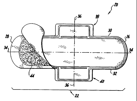
Referring to FIGS. 1 and 2, there is shown an embodiment of the present
12
CA 02579416 2007-03-06
WO 2006/034096
PCT/US2005/033281
invention, a feminine sanitary napkin 20.
The sanitary napkin 20 has a main body 22 with a first transverse side 26
defining
a front portion thereof and a second transverse side 28 defining a rear
portion thereof.
The main body also has two longitudinal sides, namely a longitudinal side 30
and a
longitudinal side 32. The sanitary napkin 20 preferably has a thickness not
exceeding
about 2.5 mm, preferably the thickness is less than 2.0 mm, more preferably
less than
1.5 mm.
The sanitary napkin 20 has a longitudinal centerline 34 that is an imaginary
line
bisecting the sanitary napkin 20 in two identical halves. Projecting laterally
outward
from each of the longitudinal sides 30, 32 is a flap 38 and 40 respectively.
The main
body 22 also has an imaginary transverse centerline 36 perpendicular to the
longitudinal
centerline 34 and simultaneously bisecting the flaps 38, 40.
As depicted in FIG. 4, the main body 22 is of a laminate construction and
preferably comprises a fluid-permeable cover layer 42, an absorbent system 44
and a fluid-impervious barrier layer 50. The absorbent system 44 may comprise
a single
layer of material or may comprise multiple layers. For example the absorbent
system
may comprise a single layer core or it may include a transfer layer and a
core.
Main Body¨Cover Layer
The cover layer 42 may be a relatively low density, bulky, high-loft non-woven
web material. The cover layer 42 may be composed of only one type of fiber,
such as
polyester or polypropylene or it may include a mixture of more than one fiber.
The cover
may be composed of bi-component or conjugate fibers having a low melting point
13
CA 02579416 2007-03-06
WO 2006/034096
PCT/US2005/033281
component and a high melting point component. The fibers may be selected from
a
variety of natural and synthetic materials such as nylon, polyester, rayon (in
combination
with other fibers), cotton, acrylic fiber and the like and combinations
thereof. Preferably,
the cover layer 42 has a basis weight in the range of about 10 gsm to about 75
gsm.
Bi-component fibers may be made up of a polyester layer and a an polyethylene
sheath. The use of appropriate bi-component materials results in a fusible non-
woven
fabric. Examples of such fusible fabrics are described in U.S. Pat. No.
4,555,430 issued
Nov. 26, 1985 to Chicopee. Using a fusible fabric increases the ease with
which the cover
layer may be mounted to the absorbent layer andJor to the barrier layer.
The cover layer 42 preferably has a relatively high degree of wettability,
although
the individual fibers comprising the cover may not be particularly
hydrophilic. The cover
material should also contain a great number of relatively large pores. This is
because the
cover layer 42 is intended to take-up body fluid rapidly and transport it away
from the
body and the point of deposition. Therefore, the cover layer contributes
little to the time
taken for the napkin to absorb a given quantity of liquid (penetration time).
Advantageously, the fibers which make up the cover layer 42 should not lose
their
physical properties when they are wetted, in other words they should not
collapse or lose
their resiliency when subjected to water or body fluid. The cover layer 42 may
be treated
to allow fluid to pass through it readily. The cover layer 42 also functions
to transfer the
fluid quickly to the other layers of the absorbent system 44. Thus, the cover
layer 42 is
advantageously wettable, hydrophilic and porous. When composed of synthetic
hydrophobic fibers such as polyester or bi-component fibers, the cover layer
42 may be
treated with a surfactant to impart the desired degree of wettability.
14
CA 02579416 2007-03-06
WO 2006/034096
PCT/US2005/033281
In one preferred embodiment of the present invention the cover is made from a
spunlace nonwoven material having from about 0 to about 100% polyester and
from
about 0 to about 100% rayon. The spunlace material may also be made from about
10%
to about 65% rayon and from about 35% to about 90% polyester. In lieu of,
and/or in
combination with the polyester, polyethylene, polypropylene or cellulosic
fiber may be
used with the rayon. Optionally, the material used for the cover layer may
include
binders such as thermoplastic binders and latex binders.
In another preferred embodiment of the present invention the cover is made
from
a spunlace nonwoven material and has a "fluid absorption time" (as defined
below) of
less than 100 s, preferably less than 50 s and most preferably less than 30 s.
In another preferred embodiment of the present invention the cover is made
from
a spunlace nonwoven material that is composed substantially entirely of
"nonabsorbent
fibers" and has a "fluid absorption time" (as defined below) of less than 100
s, preferably
less than 50 s and most preferably less than 30 s.
The term "nonabsorbent fibers" as used herein means fibers that do not retain
any
fluid within the polymer matrix of the fiber body itself. Examples of suitable
nonabsorbent fibers include polypropylene, polyester, polyethylene and
bicomponent
fibers made from combinations of polypropylene, polyester and polyethylene.
The surface of the nonabsorbent fibers may be rendered "permanently wetable"
(hydrophilic) via suitable surface finishing compositions, such as appropriate
surfactants
as well as internal surfactants. The term "permanently wetalbe" as used herein
means
that the surface of the fibers retain their wetable characteristics after the
spunlacing
CA 02579416 2007-03-06
WO 2006/034096
PCT/US2005/033281
process. Specific examples of fibers whose surface is permanently wetable are
commercially available and are set forth below in the examples.
Preferably spunlace materials according to the present invention include at
least
20% of nonabsorbent fibers by weight that have a fiber surface that is
permanently
wetable, more preferably at least 35% nonabsorbent fibers by weight that have
a fiber
surface that is permanently wetable and most preferably at least 50%
nonabsorbent fibers
by weight that have a fiber surface that is permanently wetable.
"Composed substantially entirely of nonabsorbent fibers" as used herein means
that preferably at least 90% of the fibers by weight in the spunlace cover
material are
nonabsorbent, more preferably at least 95% by weight are nonabsorbent, and
most
preferably 100% of the fibers by weight are nonabsorbent.
In another specific embodiment the cover material is a spunlace nonwoven
material that contains between about 10% and 90% polypropylene fibers by
weight and
between 90% and 10% polyester fibers by weight, more preferably between about
35%
and 65% polypropylene fibers by weight and 65% and 35% polyester fibers by
weight,
and the cover material has a fluid absorption time of less than 100 s,
preferably less than
50 s and most preferably less than 30 s.
In those embodiments of the spunlace cover material according to the present
invention wherein the spunlace cover includes a preformed web introduced prior
to hydro
entangling, the preformed web preferably makes up about 10% to about 50% by
weight
of the total cover weight. The preformed web material preferably has a basis
weight in
the range of about 5 gsm to about 20 gsm, and more preferably from about 10
gsm to
16
CA 02579416 2007-03-06
WO 2006/034096
PCT/US2005/033281
about 15 gsm.. The preformed is also preferably constructed from a
nonabsorbent
material such as polyethylene or polypropylene.
In the those embodiments of the present invention where the cover material is
a
spunlace material the cover preferably has a total basis weight of about 30
gsm to about
80 gsm and more preferably about 40 gsm to about 60 gsm.
Procedure for Determining Fluid Absorption Time of Cover Material
As discussed above spunlace cover materials in accordance with the present
invention preferably have a "fluid absorption time" (as defined below) of less
than 100 s,
preferably less than 50 s and most preferably less than 30 s.
The procedure for determining the fluid absorption time of a cover material is
provided below.
First a test fluid was prepared, the test fluid having the following
composition:
(a) 50 g of Acrysol G111 (commercially available from Rohm & Haas,
Philadelphia, PA);
(b) 975 g of distilled water (72.8 dynes/cm); and
(c) 10 g of red dye (commercially available from Sigma-Aldrich Co., St. Louis,
MO).
The resulting test fluid had a value of 42 dynes/cm.
The test procedure was conducted as follows:
(1) A 2" by 2" swatch of the cover material is laid flat on a level surface
such as a
table top. No absorbent material should be arranged under the cover material
since this
will effect the measured fluid absorption time;
17
CA 02579416 2007-03-06
WO 2006/034096
PCT/US2005/033281
(2) A .05 g drop of the test fluid is applied to the top surface of the
material using
an appropriate pipette. The terminal end of the pipette should be applied just
above the
top surface of the material so as to minimize the free fall of fluid but the
terminal end of
the pipette should not be positioned in direct abutment with the top surface
of the
material so as to force the test fluid into the material;
(3) After the drop of test fluid is applied to the material a stop watch is
started and
then the stop watch is stopped when the drop of fluid has fully entered into
the material.
(4) The above described process is repeated for five material samples and the
average fluid absorption time is calculated, this average being the "fluid
absorption time"
according to this method.
Examples of Inventive Spunlace Cover Materials
Two specific examples of cover materials according to the present invention
are
set forth below and two comparative examples are also provided. Each of the
inventive
spunlace covers were manufactured using conventional spunlacing techniques
well
known to those skilled in the art.
Inventive Spunlace Cover Example I - a hydro entangled spunlace nonwoven web
with a
basis weight of 50 gsm comprised of 50 % 2.0 dpf Type 130 HyEntangle WA
(polypropylene) fibers available from Fibervisions Inc. Covington GA and 50 %
1.4 dpf
PET fibers Series 300 available from Sabic Inc., Sittard (The Netherlands).
The 2.0 dpf
Type 130 HyEntangle WA fibers are "permanently wetable" fibers.
18
CA 02579416 2007-03-06
WO 2006/034096
PCT/US2005/033281
Inventive Spunlace Cover Example II - a hydro entangled spunlace nonwoven web
with a
total basis weight of 50 gsm comprised of a 10 gsm or 20% of total w/w%
preformed
web of spunbond PP introduced prior to hydro entangling available from PGI ,
Inc.
Charleston SC code KO-CA-5 and 40 gsm or 80 % of total w/wTo of staple fibers
that
are 1.5 dpf PET fibers Type 203 available from Wellman Inc. Charlotte, NC. In
this
example the permanently wettable "fibers" are introduced via the preformed
spunbond
PP web. In this embodiment the spunbond PP web is "permanently wettable".
Inventive Spulace Cover Example III - a hydro entangled spunlace nonwoven web
with
a basis weight of 50 gsm comprised of a 10 gsm or 20 % 2.0 dpf Type 130
HyEntangle
WA (polypropylene) fibers available from Fibervisions Inc. Covington GA and 40
gsm
or 80 % 1.5 dpf PET fibers Type 203 available from Wellman Inc., Charloette,
NC. The
2.0 dpf Type 130 HyEntangle WA fibers are "permanently wetable" fibers.
Comparative Spunlace Example I - a hydroentangled spunlace nonwoven web with a
basis weight of 50 gsm comprised of 100% 1.5 dpf PET fibers Type 203 available
from
Wellman Inc. Charlotte, NC.
Comparative Spunlace Example II ¨ a hydro entangled spunlace nonwoven web
available
from Polymer Group Inc. Charleston, SC code JM-88-10-12 with a total basis
weight of
50 gsm comprised of a 15 gsm or 30% of total w/wTo spunbond PP introduced
prior to
hydro entangling available from PGI, Inc. Charleston SC and 35 gsm or 70 % of
total
19
CA 02579416 2007-03-06
WO 2006/034096
PCT/US2005/033281
wiw% of staple fibers that are 1.5 dpf PET fibers Type 203 available from
Wellman Inc.
Charlotte, NC.
The fluid absorption times for each of the above examples were determined and
are
provided in the chart below.
Sample Fluid Absorption
Time, s
N=5
Inventive Spunlace 25.7
Example I
Inventive Spunlace 18.0
Example II
Inventive Spunlace 58.6
Example III
Comparative >146.2
Spunlace Example I
Comparative >200
Spunlace Example
Alternatively, the cover layer 42 can also be made of polymer film having
large
pores. Because of such high porosity, the film accomplishes the function of
quickly
transferring body fluid to the inner layers of the absorbent system. Apertured
co-extruded
films such described in U.S. Pat. No. 4,690,679 and available on sanitary
napkins sold by
Johnson & Johnson Inc. of Montreal, Canada could be useful as cover layers in
the
present invention.
The cover layer 42 may be embossed to the remainder of the absorbent system 44
in order to aid in promoting hydrophilicity by fusing the cover to the next
layer. Such
CA 02579416 2007-03-06
WO 2006/034096
PCT/US2005/033281
fusion may be effected locally, at a plurality of sites or over the entire
contact surface of
cover layer 42 and absorbent system 44. Alternatively, the cover layer 42 may
be
attached to the absorbent system 44 by other means such as by adhesion.
Main Body -- Absorbent System
The absorbent system 44 may comprise a single layer of material or may
comprise multiple layers. In one embodiment, the absorbent system 44 is a
blend or
mixture of cellulosic fibers and superabsorbent disposed in and amongst fibers
of that
pulp.
It is possible that the absorbent system 44 could be integrated with the cover
and/or barrier such that there is essentially only a single layer structure or
a two layer
structure including the function of the multiple layers described herein.
Cellulosic fibers that can be used in the absorbent system 44 are well known
in
the art and include wood pulp, cotton, flax and peat moss. Wood pulp is
preferred. Pulps
can be obtained from mechanical or chemi-mechanical, sulfite, lcraft, pulping
reject
materials, organic solvent pulps, etc. Both softwood and hardwood species are
useful.
Softwood pulps are preferred. It is not necessary to treat cellulosic fibers
with chemical
debonding agents, cross-linking agents and the like for use in the present
material. Some
portion of the pulp may be chemically treated as discussed in US 5,916,670 to
improved
flexibility of the product. Flexibility of the material may also be improved
by
mechanically working the material or tenderizing the material. The absorbent
system 44
can contain any superabsorbent polymer (SAP), which SAPs are well known in the
art.
For the purposes of the present invention, the term "superabsorbent polymer"
(or "SAP")
21
CA 02579416 2007-03-06
WO 2006/034096
PCT/US2005/033281
refers to materials which are capable of absorbing and retaining at least
about 10 times
their weight in body fluids under a 0.5 psi pressure. The superabsorbent
polymer particles
of the invention may be inorganic or organic crosslinked hydrophilic polymers,
such as
polyvinyl alcohols, polyethylene oxides, crosslinked starches, guar gum,
xanthan gum,
and the like. The particles may be in the form of a powder, grains, granules,
or fibers.
Preferred superabsorbent polymer particles for use in the present invention
are
crosslinked polyacrylates, such as the product offered by Sumitomo Seika
Chemicals Co.,
Ltd. Of Osaka, Japan, under the designation of SA7ON and products offered by
Stockhausen Inc..
The absorbent system 44 may comprise a material manufactured by using air-
laying means well known in the art. In a specific example, the absorbent
system 44 is an
air laid material made from cellulosic fibers, bonding materials and
components that
cannot form a bond (nonbonding materials) with the other component materials.
Examples of bonding materials include latex binders, thermoplastic particles
or
fibers that melt at the "process temperature" (as defined below), adhesives,
or
bicomponent fibers wherein at least a portion of the bicomponent fiber melts
at the
process temperature. The term "process temperature" as used herein means the
highest
temperature to which the material is subjected to during the air laying
process. The
process temperature may vary depending on the specific air laying process, and
the
process temperature is selected by those skilled in the art for a particular
air laying
process, however in order for a synthetic and/or bicomponent fiber to function
as
"bonding materials" herein they must have a melting temperature less than the
selected
process temperature. For example if an airlaid material includes polyethylene
fibers
22
CA 02579416 2007-03-06
WO 2006/034096
PCT/US2005/033281
having a melting temperature of 128 C and polyester fibers having a melting
temperature of 260 C and the process temperature is selected to be 160 then
the
polyethylene fibers would function as bonding materials and the polyester
fibers would
function as nonbonding materials.
Examples of nonbonding materials include SAP (superabsorbent polymer),
cellulosic fibers, and synthetic and bicomponent fibers having a melting
temperature that
is higher than the selected process temperature such that they will not melt
and bond at
the process temperature.
Specific examples of airlaid materials according to the present invention
include
less than 50% cellulosic fibers by weight, less than 20% bonding materials by
weight and
greater 30% nonbonding materials by weight. Specific airlaid materials
according to the
present invention have less than 20% bonding materials by weight, more
preferably less
than 15% bonding materials by weight and most preferably between about 3%-10%
bonding materials by weight. Specific examples of airlaid materials according
to the
present invention may also include an optional carrier material arranged on
either or both
surfaces of the cellulosic mixture. For purposes of the weight percentages
provided for
bonding materials and nonbinding materials herein the carrier should not be
included in
such calculations.
Specific airlaid materials according to the present invention also preferably
have
a basis weight in the range of about 50 gsm to about 600 gsm and a density in
the range
of about 0.03 g/cc to about 0.2 gicc. If a latex binder is used as the binding
material the
Tg of the latex material should be less than 25 C. Specific airlaid materials
according to
the present invention preferably have a thickness less than 5 mm and more
preferably less
23
CA 02579416 2007-03-06
WO 2006/034096
PCT/US2005/033281
than 3 mm. If a binding fiber, such as a bicomponent fiber, is used as the
binding
material then the binding fiber should have a denier per filament of equal to
3 dpf or less.
Specific inventive examples of airlaid materials that may be used as the
absorbent
material in the present invention are provided below.
Examples of Inventive Airlaid Absorbent Materials
Example Airlaid #1 - A specific airlaid absorbent material in accordance with
the
present invention was constructed as a 100 gsm airlaid (including carrier)
containing
43 % by weight wood pulp fibers available from Weyerhauser, Seattle,
Washington,
= code NB416 HC 255, 3% by weight bicomponent fiber code HC255B (PE/PET) from
Trevira GmbH, Hattersheim, Germany, 4 % latex binder from Vinamul Polymers a
unit
of National Starch and Chemical Company, Bridgewater, NJ, code Elite 21 having
a Tg
of -10 C, a cellu tissue carrier of 18% by weight from Cellu Tisue Holdings
Inc., East
Hartford Ct, and 32% by weight super absorbent polymer code M7035 from BASF
Ludwigshafen, Germay.
In Example Airlaid #1 described above the latex binder material functions as a
bonding material and the bicomponent fibers function as a bonding material
since the
process temperature selected was about 140 C which is higher than the melting
temperature of the PE portion of the bicomponent fibers. Thus in Airlaid
Example #1 the
airlaid material contains 43% cellulosic fibers, 7% bonding materials and 75%
nonbonding materials (SAP + cellulosic fibers).
The material of airlaid example #1 had a thickness of 2.0 mm.
24
CA 02579416 2007-03-06
WO 2006/034096
PCT/US2005/033281
Example Airlaid #2 - A 70 gsm airlaid (excluding carrier) containing 6% KoSa
6dpf polyester fiber, 14.6% Treveria Type HC255B (PE/PET) 3 dpf bicomponent
fiber,
46.5% wood pulp fibers, 28.6% SAP SA70 Sumitomo Seika, Osaka, Japan and 4.3%
Vinamul Polymers A Unit of National Starch and Chemical Company Bridgewater,
NJ
latex binder Code 4401 with a Tg of ¨23C. The airlaid components are cast onto
a 17-
gsm-tissue carrier.
In Example Airlaid #2 described above the latex binder functions as a bonding
material and the bicomponent fibers function as a bonding material since the
process
temperature selected was about 140 C which was higher than the melting
temperature of
the PE portion of the bicomponent fibers and less than the melting temperature
of the
polyester fibers. Thus in Airlaid Example #2 the airlaid material contains
46.5%
cellulosic fibers, 18.9% bonding materials and 81.1% nonbonding materials (SAP
+
cellulosic fibers + polyester fibers).
The material of airlaid example #1 had a thickness of 1.5 mm.
Airlaid Example #1 and #2 were made using conventional airlaying techniques
well known to those skilled in the art.
It is possible that the absorbent system 44 could be integrated with the cover
and/or barrier such that there is essentially only a single layer structure or
a two layer
structure including the function of the multiple layers described herein.
Main Body-Barrier Layer
Underlying the absorbent layer 44 is a barrier layer 50 comprising liquid-
impervious film material so as to prevent liquid that is entrapped in the
absorbent system
CA 02579416 2007-03-06
WO 2006/034096
PCT/US2005/033281
44 from egressing the sanitary napkin and staining the wearer's undergarment.
The barrier
layer 50 is preferably made of polymeric film, although it may be made of
liquid
impervious, air-permeable material such as repellent-treated non-woven or
micropore
films or foams.
Positioning adhesive 58 may be applied to a garment facing side of the barrier
layer for securing the napkin 20 to the garment during use. The positioning
adhesive 58
may be covered with removable release paper 60 so that the positioning
adhesive is
covered by the removable release paper 60 prior to use.
The barrier layer may be breathable, i.e., permits vapor to transpire. Known
materials for this purpose include nonwoven materials and microporous films in
which
microporosity is created by, inter alia, stretching an oriented film. Single
or multiple
layers of permeable films, fabrics, melt-blown materials, and combinations
thereof that
provide a tortuous path, and/or whose surface characteristics provide a liquid
surface
repellent to the penetration of liquids may also be used to provide a
breathable backsheet.
The cover layer 42 and the barrier layer 50 are joined along their marginal
portions so as
to form an enclosure or flange seal that maintains the absorbent layer 44
captive. The
joint may be made by means of adhesives, heat-bonding, ultrasonic bonding,
radio
frequency sealing, mechanical crimping, and the like and combinations thereof.
Main Body - Stabilizing Layer
As shown in Figures 5 and 6, the sanitary napkin 20 may further optionally
include a stabilizing layer 52 arranged between the cover layer 42 and the
barrier 50.
The stabilizing layer 52 may be arranged between the absorbent system 44 and
the cover
26
CA 02579416 2007-03-06
WO 2006/034096
PCT/US2005/033281
layer 42 or it may be arranged between the absorbent system 44 and the barrier
50. The
stabilizing layer 52 is intended to provided the napkin with a higher flexural
resistance
(MCB) in a localized area. The stabilizing layer 52 is intended to enhance the
structural
integrity of the napkin 20 in a localized area while at the same time still
permitting the
overall nature of the napkin to be "drapeable".
The stabilizing layer 52 preferably has a length L I that is less than a
length L2 of
the absorbent system 44. In this manner, the napkin generally has a first
portion 54 that
is located outside the dimensions of the stabilizing layer 52 and a second
portion 56
located within the dimensions of the stabilizing layer 52. The material for
the stabilizing
layer 52 is selected such that the napkin 20 has a flexural resistance (MCB)
that is greater
within the dimensions of the stabilizing layer 52, i.e. within second portion
56, than
outside the dimensions of the stabilizing layer 52, i.e. within the first
portion 54.
Thus, the napkin will have at least a first MCB value outside the dimensions
of
the stabilizing 52 and a second MCB value within the dimensions of the
stabilizing layer
52, the first MCB value being less than the second MCB value. Preferably the
second
MCB value is at least 400 g. The MCB values of the first portion 54 and the
second
portion 56 may be calculated in the same manner set forth in the "Procedure
for
Measuring Modified Circular Bend Stiffness (MCB) and Basis Weight (BW)" set
forth
above.
The width WI of the stabilizing layer 52 is preferably selected such that it
is the
same as the width W2 of the absorbent system 44. Preferably the stabilizing
layer has a
length Ll of at least 37.5 mm and width W1 of at least 37.5 mm.
27
CA 02579416 2012-08-29
If the stabilizing layer 52 is arranged between the cover layer 42 and the
absorbent system 44, the material comprising the stabilizing layer 52 should
be
selected such that it readily transmits fluid to the absorbent system 44. For
example,
the stabilizing layer 52 may comprise a nonwoven material including a blend or
mixture of synthetic and/or cellulosic fibers. Suitable specific material
compositions
will be apparent to those skilled in the art.
If the stabilizing layer 52 is arranged between the absorbent system 44 and
the
barrier 50, the material comprising the stabilizing layer may be liquid
impermeable. In
this manner, the stabilizing layer 52 may assist the barrier 50 in preventing
fluid from
escaping from the absorbent article.
Alternatively, if the stabilizing layer is arranged between the absorbent
system
44 and the barrier 50, the material comprising the stabilizing layer may be
absorbent
such that it functions as a secondary core. For example, the stabilizing layer
52 may
comprise a nonwoven material including a blend or mixture of cellulosic fibers
and
SAP.
Finally, the stabilizing layer 52 may be arranged on the outer surface of the
barrier. In such an embodiment the material comprising the stabilizing layer
is preferably
liquid impermeable and thus functions as a secondary barrier.
Absorbent articles of this invention may or may not include wings, flaps or
tabs for
securing the absorbent article to an undergarment. Wings, also called, among
other things,
flaps or tabs, and their use in sanitary protection articles is described in
U.S. Patent. No.
4,687,478 to Van Tilburg; U.S. Patent No. 4,589,876 also to Van Tilburg, U.S.
Patent No.
4,900,320 to McCoy, and U.S. Patent No. 4,608,047 to Mattingly. As
28
CA 02579416 2007-03-06
WO 2006/034096
PCT/US2005/033281
disclosed in the above documents, wings are generally speaking flexible and
configured
to be folded over the edges of the underwear so that the wings are disposed
between the
edges of the underwear.
The absorbent article of the present invention may be applied to the crotch by
placing the garment-facing surface against the inside surface of the crotch of
the garment.
Various methods of attaching absorbent articles may be used. For example,
chemical
means, e.g., adhesive, and mechanical attachment means, e.g., clips, laces,
ties, and
interlocking devices, e.g., snaps, buttons, VELCRO (Velcro USA, Inc.,
Manchester, NH),
zipper, and the like are examples of the various options available to the
artisan.
Adhesive may include pressure sensitive adhesive that is applied as strips,
swirls,
or waves, and the like. As used herein, the term pressure-sensitive adhesive
refers to any
releasable adhesive or releasable tenacious means. Suitable adhesive
compositions,
include, for example, water-based pressure-sensitive adhesives such as
acrylate
adhesives. Alternatively, the adhesive composition may include adhesives based
on the
following: emulsion or solvent-borne adhesives of natural or synthetic
polyisoprene,
styrene-butadiene, or polyacrylate, vinyl acetate copolymer or combinations
thereof; hot
melt adhesives based on suitable block copoylmers - suitable block copolymers
for use in
the invention include linear or radial co-polymer structures having the
formula (A-B)x
wherein block A is a polyvinylarene block, block B is a poly(monoalkenyl)
block, x
denotes the number of polymeric arms, and wherein x is an integer greater than
or equal
to one. Suitable block A polyvinylarenes include, but are not limited to
Polystyrene,
Polyalpha-methylstyrene, Polyvinyltoluene, and combinations thereof. Suitable
Block B
poly(monoalkenyl) blocks include, but are not limited to conjugated diene
elastomers
29
CA 02579416 2007-03-06
WO 2006/034096
PCT/US2005/033281
such as for example polybutadiene or polyisoprene or hydrogenated elastomers
such as
ethylene butylene or ethylene propylene or polyisobutylene, or combinations
thereof.
Commercial examples of these types of block copolymers include KratonTM
elastomers
from Shell Chemical Company, VectorTM elastomers from Dexco, SolpreneTM from
Enichem Elastomers and StereonTM from Firestone Tire & Rubber Co.; hot melt
adhesive based on olefin polymers and copolymers where in the olefin polymer
is a
terpolymer of ethylene and a co-monomers, such as vinyl acetate, acrylic acid,
methacrylic acid, ethyl acrylate, methyl acrylate, n-butyl acrylate vinyl
silane or maleic
anhydride. Commercial examples of these types of polymers include Ateva(
polymers
from AT plastics), Nucrel( polymers from DuPont), Escor (from Exxon Chemical).
Where adhesive is used, a release strip may be applied to protect the adhesive
on
the absorbent article prior to attaching the absorbent article to the crotch.
The release
strip can be formed from any suitable sheet-like material adheres with
sufficient tenacity
to the adhesive to remain in place prior to use but which can be readily
removed when the
absorbent article is to be used. Optionally , a coating may be applied to
release strip to
improve the ease of removabilty of the release strip from the adhesive. Any
coating
capable of achieving this result may be used, e.g., silicone.
Any or all of the cover, absorbent layer, transfer layer, backsheet layer, and
adhesive layers may be colored. Such coloring includes, but is not limited to,
white,
black, red, yellow, blue, orange, green, violet, and mixtures thereof. Color
may be
imparted according to the present invention through dying, pigmentation, and
printing.
Colorants used according the present invention include dyes and inorganic and
organic
pigments. The dyes include, but are not limited to, anthraquinone dyes
(Solvent Red 111,
CA 02579416 2007-03-06
WO 2006/034096
PCT/US2005/033281
Disperse Violet 1, Solvent Blue 56, and Solvent Green 3), Xanthene dyes
(Solvent Green
4, Acid Red 52, Basic Red 1, and Solvent Orange 63), azine dyes (Jet black),
and the like.
Inorganic pigments include, but are not limited to, titanium dioxide (white),
carbon black
(black), iron oxides (red, yellow, and brown), chromium oxide (green), ferric
ammonium
ferrocyanide (blue), and the like.
Organic pigments include, but are not limited to diarylide yellow AAOA
(Pigment Yellow 12), diarylide yellow AAOT (Pigment Yellow 14), phthalocyanine
blue
(Pigment Blue 15), litho! red (Pigment Red 49:1), Red Lake C (Pigment Red),
and the
like.
The absorbent article may include other known materials, layers, and
additives,
such as, foam, net-like material, perfumes, medicaments or pharmaceutical
agents,
moisturizers, odor control agents, and the like. The absorbent article can
optionally be
embossed with decorative designs.
The absorbent article may be packaged as unwrapped absorbent articles within a
carton, box or bag. The consumer withdraws the ready-to-use article as needed.
The
absorbent article may also be individually packaged (each absorbent article
encased
within an overwrap).
Also contemplated herein include asymmetrical and symmetrical absorbent
articles having parallel longitudinal edges, dog bone- or peanut-shaped, as
well as articles
having a tapered construction for use with thong-style undergarments.
From the foregoing description, one skilled in the art can ascertain the
essential
characteristics of this invention, and without departing from the spirit and
scope thereof,
can make various changes and modifications. Embodiments set forth by way of
31
CA 02579416 2007-03-06
WO 2006/034096
PCT/US2005/033281
illustration are not intended as limitations on the variations possible in
practicing the
present invention.
32
CA 02579416 2007-03-06
WO 2006/034096
PCT/US2005/033281
INVENTIVE SAMPLES
Inventive Sample 1 having a two layer spunlace nonwoven cover which has a top
body
facing layer of 56 gsm of PET fibers and a bottom rayon layer which is 19 gsm.
The
absorbent layer that is directly underneath the cover consists of wetlaid
tissue carriers
(17 grams per square meter basis weight , produced by Cellu Tisue Holdings
Inc., East
Hartford Ct.) on both faces with a mixture of wood pulp, polyester fibers and
Sumitomo
SA70 SAP disposed between the layers. The pulp is bleached softwood pulp,
produced
by a kraft process. Approximately 20% of the pulp has been mercerized. The
total
composite has a basis weight of 250 gsm and contains 40% superabsorbent
(Sumitomo
SA70) and 6% polyester staple fibers (3.0 DPF by 1.5"inch cut length, KOSA
#611153,
Salisbury, North Carolina). The airlaid machine which produces this material
consists of
unwinds, hammermills, air-laid forming heads, SAP dispensers, and a heated
calendering
station with a pattern roll and a flat anvil roll. Fluff pulp mixed with SAP
and PET fibers
in the air-laid forming chambers is cast on the first carrier tissue with a
strong vacuum
underneath. Before the composite reaches the calendering station another
tissue is
introduced from the top. It is then calender between the flat anvil roll and
the patterned
calendar roll. The calendar roll pattern consists of a matrix of diamonds with
lines
between the diamonds raised to a height of 0.075". The diamonds have a major
axis of
0.325" and a minor axis of 0.201". The diamonds have a spacing of 0.046"
between
them. After the heat emboss calendering, the embossed area between the
diamonds had
a density of about 0.4 g/cc and the diamond shaped raised area has density of
0.15 g/cc.
33
CA 02579416 2007-03-06
WO 2006/034096
PCT/US2005/033281
The barrier film, below the absorbent layer is a 0.9 mil polyethylene film
produced by
Pliant Corp, Pliant # 3492A. The absorbent facing surface of the barrier had
5.9 mg/sq in
of Fuller 1023 adhesive applied to it to hold the product together. The
absorbent facing
surface of the cover had 2.6 mg/sq in of Fuller 1023 adhesive. The garment
facing
surface of the barrier was coated with 20 mg/sq inch of a pressure sensitive
adhesive
intended for panty attachment, Fuller 1417.
Inventive Sample 2 having a two layer spunlace nonwoven cover which has a top
body
facing layer of 56 gsm of PET fibers and a bottom rayon layer which is 19 gsm.
The
absorbent layer that is directly underneath the cover consists of wetlaid
tissue carriers
(17 grams per square meter basis weight, produced by Cellu Tisue Holdings
Inc., East
Hartford Ct.) on both faces with a mixture of wood pulp, polyester fibers and
Sumitomo
SA70 SAP disposed between the layers. The pulp is bleached softwood pulp,
produced
by a kraft process. Approximately 20% of the pulp has been mercerized. The
total
composite has a basis weight of 175 gsm and contains 40% superabsorbent
(Sumitomo
SA70). The airlaid machine which produces this material consists of unwinds,
hammermills, air-laid forming heads, SAP dispensers, and a heated calendering
station
with a pattern roll and a flat anvil roll. Fluff pulp mixed with SAP in the
air-laid forming
chambers is cast on the first carrier tissue with a strong vacuum underneath.
Before the
composite reaches the calendering station another tissue is introduced from
the top. It is
then calender between the flat anvil roll and the patterned calendar roll. The
calendar roll
pattern consists of a matrix of diamonds with lines between the diamonds
raised to a
height of 0.075". The diamonds have a major axis of 0.325" and a minor axis of
0.201".
34
CA 02579416 2007-03-06
WO 2006/034096
PCT/US2005/033281
The diamonds have a spacing of 0.046" between them. After the heat emboss
calendering, the embossed area between the diamonds had a density of about 0.4
g/cc and
the diamond shaped raised area has density of 0.15 g/cc. The barrier film,
below the
absorbent layer is a 0.9 mil polyethylene film produced by Pliant Corp, Pliant
# 3492A.
The absorbent facing surface of the barrier had 5.9 mg/sq in of Fuller 1023
adhesive
applied to it to hold the product together. The absorbent facing surface of
the cover had
2.6 mg/sq in of Fuller 1023 adhesive. The garment facing surface of the
barrier was
coated with 20 mg/sq inch of a pressure sensitive adhesive intended for panty
attachment,
Fuller 1417.
Inventive Sample 3 having a barrier layer of 0.9 mil polyethylene film
produced by Pliant
Corp, #3492A with 5.9 mg/sq in of Fuller 1023 adhesive applied to the cover
facing
surface of the barrier layer. 1.2 grams of Sumitomo J550 superabsorbent
polymer
powder was evenly sprinkled onto a 50mm by 172 mm rectangle in the center of
the
barrier film so that the SAP powder was help in place by the adhesive. A 30
gsm thermal
bonded polypropylene cover (Code #65130 available from Polymer Group Inc.
Charleston, SC) was placed on top of the SAP and barrier film. The cover had
2.6 mg/sq
in of Fuller 1023 adhesive on the SAP facing side to bond it to the SAP and
the barrier
film. The cover an barrier films extended about 10 mm beyond the SAP
containing
region and were secured to each other. The garment facing surface of the
barrier was
coated with 20 mg/sq inch of a pressure sensitive adhesive intended for panty
attachment,
Fuller 1417.
CA 02579416 2007-03-06
WO 2006/034096
PCT/US2005/033281
Inventive Sample 4 having a cover layer of 50 gsm spunlaced
polypropylene/polyester a
core of 70 gsm (excluding carrier) through air bonded airlaid pulp and a
barrier of 0.7
mil polypropylene film from Pliant, code X347 IA. The core is a 70 gsm airlaid
(excluding carrier) containing 6% KoSa 6dpf polyester fiber, 14.6% Treveria
Type 255
3dpf bicomponent fiber, 46.5% wood pulp fibers, 28.6% SAP SA70 Sumitomo Seika,
Osaka, Japan and 4.3% Vinamul Polymers A Unit of National Starch and Chemical
Company Bridgewater, NJ latex binder Code 4401 with a Tg of ¨23C. The airlaid
components are cast onto a 17-gsm-tissue carrier. The cover had 2.6 mg/sq.in
of Fuller
1023 on the absorbent facing side and the barrier had 5.9 mg/sq in of Fuller
1023 on the
absorbent facing side. The garment-facing surface of the barrier was coated
with 20
mg/sq inch of a pressure sensitive adhesive intended for panty attachment,
Fuller 1417.
Comparative Sample #1 Carefree Perfect Fit Pantiliner
Comparative Sample #2 Kotex Lightdays Pantiliner
Comparative Sample #3 Always Ultrathin Sanitary Napkin
Comparative Sample #4 Stayfree Ultrathin Overnight Sanitary Napkin.
Comparative Sample #5 Libra Invisible Sanitary Napkin (Australia)
Comparative Sample #6 Carefree Ultra Dry Pantiliner
The inventive samples and comparative samples set forth above were tested
according to
the test method set forth herein, the results of which are set forth in the
table provided
below.
= 36
CA 02579416 2007-03-06
WO 2006/034096
PCT/US2005/033281
Basis Weight MCB Thickness BW/MCB Rewet FPT Al
, (gsm) (g) (mm) , (1/m2) (8) (s)
Inventive 419 101 2.3 4.15 1.75 17.91 1.71
_ Sample 1 ,
Inventive 330 114 1.7 - 2.89 . 1.28 41.16 1.74
Sample 2 _
Inventive 256 12.1 1.2 21.16 .41 = 93.44 1.78
Sample 3
Inventive 260 62 1.43 4.19 4.38 24.35 1.27
Sample 4
Comparative 116 20 .85 5.80 6.27 499.88 0
Sample 1 _
Comparative 234.66 131.28 2.0 1.79 5.575 17.96
1.09
Sample 2
Comparative 292 247 2.55 ' 1.18 .05 5.8 2.0
Sample 3 _
Comparative 306 433 2.69 .71 .15 4.96 2.0
=
Sample 4 .
'
Comparative 569 475 3.01 1.2 .307 5.55 1.97
Sample 5 _
Comparative 351 112 3.32 ' 3.13 1.21 7.1 1.82
Sample 6
Products set forth in the above chart having a thickness less than or equal to
about
2.5 mm are shown in the graph provided below.
37
CA 02579416 2007-03-06
WO 2006/034096
PCT/US2005/033281
Absorbency vs Drape (thickness <=2.5mm)
2.5
2.0 - = N:Nem
x
CD
-o
_a
u) 0.5 = Comparitive Samples
M Inventive Samples
0.0 l =
1 3.2 10 32
BW/MCB
Procedure for Measuring Average Absorbent Capacity (AC)
Each of the inventive sample products 1-4 and comparative sample products 1-6
were further tested to determine the average absorbent capacity (AC) of the
products.
The test method for determining the average absorbent capacity (AC) is set
forth below.
At least three new product samples, are required to the conduct the average
absorbent capacity test described below.
The average absorbent capacity test is conducted on 37.5 mm X 37.5 mm square
test specimens cut from the product sample. The cut square 37.5 mm X 37.5 mm
test
specimens are taken from the corresponding product locations as those samples
taken
from the products used in the MCB and AI tests described above.
Prior to doing the test, at least six 60 mm X 60 mm square envelopes are
constructed from a lightweight nonwoven such as 0.7 ounce per sq yard through
air
38
CA 02579416 2007-03-06
WO 2006/034096
PCT/US2005/033281
bonded web of bicomponent fibers. A suitable example of the nonwoven material
is PGI
code #4128. The envelope can be formed by folding a 120 mm X 60 mm square
section
and heat sealing the sides with the sample enclosed. Other envelope
constructions can
be use as long as they permit unhindered absorption of the test fluid to the
sample during
the submergence portion of the test and unhindered dripping during the
dripping portion.
An envelope, without the test specimen, is submerged in a saline solution
(0.9%)
for 15 minutes, and then hung so that saline can freely drip for 12 minutes.
The wet
weight of the envelope is then measured to the nearest one hundredth of a
gram. This
procedure is conducted for three envelope samples and the average wet weight
of the
envelope is determined.
The weight of each of the three dry 37.5 mm X 37.5 mm test specimens is
measured before beginning the test.
A 37.5 mm X 37.5 mm test specimen is inserted in an dry envelope and the
envelope is submerged in a saline solution (0.9%) for 15 minutes and then hung
so that
saline can freely drip for 12 minutes. The wet weight of the combined envelope
and test
specimen are then measured to the nearest one hundredth of a gram. The dry
weight of
the test specimen and the average wet weight of the envelope alone are then
subtracted to
determine the absorbent capacity of the test specimen. This is repeated for
three 37.5 mm
X 37.5 mm test specimens and the absorbent capacity average is taken to
provide the
average absorbent capacity (AC). A chart is provided below which provides the
average
absorbent capacity (AC) for each of the inventive sample products 1-4 and
comparative
sample products 1-6.
39
CA 02579416 2007-03-06
WO 2006/034096
PCT/US2005/033281
Absorbent
Capacity (g)
(AC)
Inventive 12.24
Sample 1
Inventive 9.52
Sample 2
Inventive 10.61
Sample 3
Inventive 4.82
Sample 4
Comparative .95
Sample 1
Comparative 2.67
Sample 2
Comparative 5.32
Sample 3
Comparative 9.63
Sample 4
Comparative 8.44
Sample 5
Comparative 1 1.32
Sample 6
Each of the inventive samples described above were constructed without a
stabilizing layer 52 as described above with reference to Figures 5 and 6.
However, each
of the inventive samples described above could be constructed to include such
a
stabilizing layer 52. For example, inventive sample 5 described in detail
below was
constructed to include a stabilizing layer 52.
Inventive Sample 5
Inventive sample 5 had the same construction as inventive sample 2 described
above but further included a stabilizing layer arranged between the cover and
the
absorbent layer. The stabilizing layer was constructed from 102 gsm spunbond
polypropylene, commercially available from BBA Fiberweb Filtration as
Typar/Tekton
Filtration Grade Sponbonded Polypropylene Style Number 3301N. The dimensions
of
CA 02579416 2007-03-06
WO 2006/034096
PCT/US2005/033281
the stabilizing layer were approximately 40 mm x 40 mm and the stabilizing
layer was
arranged in the center of the product.
Inventive Sample 5 was tested to determine the MCB value within the area
defined by stabilizing layer and outside the area of the stabilizing layer,
the MCB values
MCB (g) within Stabilizing Layer MCB (g) outside
Area Stabilizing Layer Area
Inventive Sample 5 526 114
In view of the above absorbent articles according to the present invention
provide
the unique combination of a highly flexible, drapeable, absorbent article that
has
Applications of the absorbent article according to the present invention for
sanitary and other health-care uses can be accomplished by any sanitary
protection,
incontinence, medical and absorbent methods and techniques as are presently or
prospectively known to those skilled in the art. Thus, it is intended that the
present
41