Note: Descriptions are shown in the official language in which they were submitted.
CA 02579513 2007-03-06
WO 2006/030416 PCT/IL2005/000947
1
CUTTING INSERT AND CUTTING TOOL
FIELD OF THE INVENTION
The present invention relates to a metal cutting tool having an
adjusting mechanism for adjusting the position of a cutting insert secured in
the cutting tool relative tllereto, and to a cutting insert for securing in
the
metal cutting tool, and in particular to a metal cutting tool having a
plurality
of such cutting inserts mounted on a periphery thereof.
BACKGROUND OF THE INVENTION
Such metal cutting tools require accurate positioning of an
operative cutting edge relative to the tool. Precise adjustment of the
operative cutting edge position is particularly important for finishing
operations. However, adjusting mechanisms require installation space in
the tool. Therefore, the adjusting mechanism should preferably be
dimensionally compact so as to occupy as little space as possible in the
cutting tool. This requirement is especially important in tools used for metal
removal inside cavities of the work-piece, such as boring or reaming tools,
because the dimensions of the bore limit the maximum diameter of the tool,
CA 02579513 2007-03-06
WO 2006/030416 PCT/IL2005/000947
2
and thus the space available for installation of the cutting inserts and the
adjustment mechanisms in the tool.
U.S. Patent No. 4,850,757 to Stashko discloses such a reamer
comprising a holder having a recess into which a disposable cutting insert is
fitted. The insert is held in place by a clamping member which bears
against a surface of the insert and which is attached to the holder by a
clamping screw. Radial adjustment of the insert can be effected by
adjusting screws having camming surfaces which bear against a
corresponding camming surface of the insert. However, the insert
adjustment and clamping mechanisms occupy considerable space at the
working end of the tool.
U.S. Patent No. 4,425,063 to Striegl discloses a reamer with a
flat rectangular reversible cutting bit, possessing a cutting edge extending
parallel to a longitudinal axis of a revolvable body. The flat rectangular
cutting insert has four indexing positions, and occupies a relatively small
space on the revolvable body. The flat rectangular cutting bit is detachably
mounted in a recess of the revolvable body. However, the adjusting
mechanism in US 4,425,063 precludes radial adjustment of the cutting edge
position of the cutting insert.
U.S. Patent No. 4,611,516 to Hochmuth, et al. discloses a rotary
metal cutting tool having a plurality of radially adjustable cutting inserts
mounted on the periphery thereof. Each cutting insert is clamped by a
clamping jaw, and is urged radially outwardly by an adjusting screw
positioned radially inwardly therefrom, thereby occupying considerable
space near the center of the tool body, and limiting the number of cutting
inserts which can be installed.
CA 02579513 2007-03-06
WO 2006/030416 PCT/IL2005/000947
3
SUMMARY OF THE INVENTION
In accordance with the present invention, there is provided a
metal cutting tool comprising at least one insert pocket having a cutting
insert removably secured therein in communication with an adjusting
mechanism; the cutting insert comprising at least one insert adjusting slot
extending between two opposing major faces and opening out to each major
face at an adjusting aperture. The adjusting mechanism comprises at least
one adjusting member having an adjusting member top face. In a major
face view of the at least one cutting insert, the adjusting aperture of each
insert major face at least partially overlaps the adjusting member top face.
Preferably, the cutting insert overlies the adjusting member top
face.
Further preferably, the cutting insert comprises two opposing end
faces, each end face extending between two major edges formed at the
intersection thereof with the two opposing major faces, each end face
comprises an abutment surface extending between the major edges.
Yet further preferably, a tangentially-leading radially-outermost
major edge of the cutting insert is continuously positionable between a first
radial position and a second radial position; in the first radial position the
tangentially-leading radially-outermost major edge is positioned at a first
radial distance 01 from the axis of rotation of the cutting tool; in the
second
radial position the tangentially-leading radially-outermost major edge is
positioned at a second radial distance 02 from the axis of rotation of the
cutting tool, and the second radial distance 02 is greater than the first
radial
distance 01.
If desired, the tangentially-leading radially-outermost major edge
is positioned by inserting a key into an adjusting socket formed in the
CA 02579513 2007-03-06
WO 2006/030416 PCT/IL2005/000947
4
adjusting member top face, and turning the at least one adjusting member of
the adjusting mechanism.
Preferably, the adjusting mechanism comprises an adjusting plate
having a plate top face, a plate bottom face, and a plate peripheral face
extending therebetween transversely to the plate bottom face having at least
one plate adjusting slot extending between and opening out to the plate
bottom face and the plate top face, the plate top and bottom faces forming
an acute wedge plate angle cp therebetween.
Further preferably, the wedge plate angle cp is less than 45 .
Yet further preferably, the wedge plate angle cp is 15 .
If desired, the adjusting plate comprises a plate clamping slot
extending between the plate top face and the plate bottom face.
If further desired, a radially-innermost major face of the cutting
insert abuts the plate top face.
If yet further desired, the plate bottom face abuts a recess base of
a recess formed in a pocket base of the insert pocket.
Typically, the adjusting plate is adjustably positioned parallel to
the recess base by adjustably positioning the at least one adjusting member
Alternatively, the adjusting mechanism comprises at least one
adjusting wedge having a wedge bottom and a wedge peripheral surface
extending perpendicularly thereto. The wedge peripheral surface comprises
a leading surface portion extending from the wedge bottom to a wedge
intermediate surface and a back surface portion extending between the
wedge bottom and a wedge top. The wedge intermediate surface and the
wedge bottom form an acute internal wedge intermediate angle co
therebetween.
Preferably, the wedge intermediate angle co is less than 45 .
CA 02579513 2007-03-06
WO 2006/030416 PCT/IL2005/000947
If desired, the wedge intermediate angle is 20
If further desired, a wedge support wall extends from the wedge
top towards the wedge intermediate surface perpendicularly thereto.
Generally, a threaded wedge adjusting through-hole extends
5 along a wedge-hole axis H perpendicularly from wedge bottom to the
wedge intermediate surface and engages therein a threaded member top
portion of the adjusting member.
Preferably, the at least one adjusting wedge is located in a wedge
recess extendirig inwardly from a pocket base of the insert pocket. The
wedge base comprises a threaded wedge recess adjusting bore having an
adjusting bore axis B extending inwardly from the wedge recess base
perpendicularly thereto.
Further preferably, a member bottom portion of the adjusting
member is threaded into the wedge recess adjusting bore and the at least one
adjusting wedge is adjustably positioned relative to a wedge recess base of
the wedge recess by rotating the at least one adjusting member.
Further in accordance with the present invention, there is
provided a cutting insert comprising two opposing insert end faces and an
insert peripheral face extending therebetween, the insert peripheral face
comprising two opposing insert major faces extending transversely between
the insert end faces, the cutting insert having an insert clamping hole
extending between the two opposing insert major faces and disposed
between two insert adjusting slots extending between the two insert major
faces.
Preferably, each insert adjusting slot forms an adjusting aperture
at a junction thereof with each insert major face, each adjusting aperture
having a length dimension taken perpendicularly to the insert end faces and
CA 02579513 2007-03-06
WO 2006/030416 PCT/IL2005/000947
6
a width dimension taken perpendicularly to the length dimension, the length
dimension being greater than the width dimension.
Yet further in accordance with the present invention, there is
provided a method of adjusting a position of a cutting insert removably
secured in a metal cutting tool. The method comprising the steps of:
providing an adjusting mechanism comprising at least one adjusting
member having an adjusting member top face with an adjusting socket
designed to receive a key formed therein;
providing the cutting insert with at least one insert adjusting slot
extending between and opening out to two opposing insert major faces at an
adjusting aperture;
securing the cutting insert in the cutting tool so that the at least one
adjusting member top face and the adjusting aperture of each insert major
face at least partially overlap in a major face view of the cutting insert;
inserting the key through the insert adjusting slot to the adjusting
socket; and
rotating the key; whereby the position of the cutting insert relative to
the cutting tool is adjusted.
BRIEF DESCRIPTION OF THE DRAWINGS
For a better understanding of the present invention and to show
how the same may be carried out in practice, reference will now be made to
the accompanying drawings, in which:
Fig. 1 is a perspective view of a reamer of a first embodiment of the
present invention;
Fig. 2 is an exploded perspective view of the reamer shown in Fig. 1;
CA 02579513 2007-03-06
WO 2006/030416 PCT/IL2005/000947
7
Fig. 3 is a perspective view of a cutting insert of the reamer shown in
Figs. 1 and 2;
Fig. 4 is a top view of a major face of the cutting insert shown in
Fig. 3;
Fig. 5 is a bottom perspective view of an adjusting plate of the reamer
shown Fig 2;
Fig. 6 is a top perspective view of the adjusting plate shown in Fig. 5;
Fig. 7 is a bottom view of the adjusting plate shown in Fig. 5;
Fig. 8 is a cross sectional view of the adjusting plate, taken along the
line VIII-VIII in Fig. 7;
Fig. 9 is a cross sectional view of the adjusting plate, taken along the
line IX-IX in Fig. 7
Fig. 10 is a view of the reamer shown in Fig 1, with the cutting inserts
and the adjusting mechanisms removed;
Fig. 11 is a top view of an insert pocket shown in Fig. 10;
Fig. 12 is a cross-sectional view of the insert pocket taken along lines
XII-XII in Fig. 11;
Fig. 13 is a detail view of the reamer shown in Fig. 1, showing a top
view of the major face of the cutting insert;
Fig. 14 is a cross-sectional view taken along the line XIV-XIV in
Fig. 13, showing the cutting insert and the adjusting plate (with the
clamping screw and the biasing element removed for clarity);
Fig. 15 is a cross-sectional view taken along the line XV XV in
Fig. 13, showing the cutting insert, the adjusting plate, the insert pocket
and
an adjusting member in a first position;
CA 02579513 2007-03-06
WO 2006/030416 PCT/IL2005/000947
8
Fig. 16 is the cross sectional view taken along the line XV-XV in Fig.
13, showing the cutting insert, the adjusting plate, the insert pocket and the
adjusting member in a second position;
Fig. 17 is a perspective view of a reamer of a second embodiment of
the present invention;
Fig. 18 is an exploded perspective view of the reamer shown in Fig.
17;
Fig. 19 is a bottom perspective view of an adjusting plate of the
reamer shown Fig 18;
Fig. 20 is a top perspective view of the adjusting plate shown in Fig.
19;
Fig. 21 is a cross sectional view of the adjusting plate, taken along the
plane XXI-XXI in Fig. 20;
Fig. 22 is a perspective view of the reamer shown in Fig 17, with the
cutting inserts and the adjusting mechanisms removed;
Fig. 23 is a top view of an insert pocket shown in Fig. 22, taken along
an adjusting screw axis;
Fig. 24 is a cross-sectional view of the insert pocket taken along lines
XXIV-XXIV in Fig. 23;
Fig. 25 is a detail view the reamer shown in Fig. 17, showing a top
view of the major face of the cutting insert;
Fig. 26 is a cross-sectional view taken along the line XXVI-XXVI in
Fig. 25;
Fig. 27 is a cross-sectional view taken along the line XXVII-XXVII in
Fig. 25, showing the cutting insert in an insert first position;
CA 02579513 2007-03-06
WO 2006/030416 PCT/IL2005/000947
9
Fig. 28 is the cross sectional view taken along the line XXVII-XXVII
in Fig. 25, showing the cutting insert in an insert second position.
DETAILED DESCRIPTION OF THE INVENTION
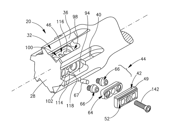
Attention is first drawn to Fig. 1. A reamer 20 of a first
embodiment of the present invention comprises a tool body 22 of a
generally cylindrical shape having an axis of rotation A defining a front-to-
rear direction and a direction of rotation R. The tool body 22 comprises a
rear tool shank 24 and a front tool cutting portion 26. The tool cutting
portion 26 comprises a tool front face 28 and a cutting-portion peripheral
surface 30 extending axially rearwardly therefrom. It should be noted that
directional terms appearing throughout the specification and claims, e.g.
"front", "rear", "leading", "trailing", etc., (and derivatives thereof) are
for
illustrative purposes only, and are not intended to limit the scope of the
appended claims.
The cutting-portion peripheral surface 30 comprises a plurality of
flutes 32 extending axially rearwardly from the tool front face 28 and
inwardly from the cutting-portion peripheral surface 30. The flutes 32
define therebetween mounting portions 34. Each flute 32 has a generally
asymmetrical V-shape and colnprises a flute leading face 36, a flute bottom
face 38 and a flute trailing,face 40. Each mounting portion 34 extends from
the flute trailing face 40 of a preceding flute 32 to the flute leading face
36
of a following flute 32, and comprises a cutting insert 42 detachably secured
therein. As shown in Fig. 2, each cutting insert 42 is in communication with
an adjusting mechanism 44. The cutting insert 42 and the adjusting
mechanism 44 are mounted in an insert pocket 46 located in the mounting
portion 34, so that when secured in the reamer 20, the cutting insert 42
overlies the adjusting mechanism 44 in the radial direction.
CA 02579513 2007-03-06
WO 2006/030416 PCT/IL2005/000947
Attention is now drawn to Figs. 3 and 4. The cutting insert 42 is
of a generally prismoidal shape and comprises two opposing insert end
faces 48 and an insert peripheral face 50 which extends therebetween. The
insert peripheral face 50 comprises two opposing insert major faces 52 and
5 two opposing insert minor faces 54 disposed transversely to the insert end
faces 48 and the insert major faces 52. The junction of the insert peripheral
face 50 and each insert end face 48 defines an insert peripheral edge 56
having two parallel insert major edges 57 each defined at an intersection of
the insert end face and an adjacent insert major face 52. Each insert end
10 face 48 is formed with a planar insert abutment surface 49 located between
the two insert major edges 57 of the insert end face 48 and extending
between the two opposing insert minor faces 54 perpendicularly to the insert
major and minor faces 52, 54. At least a portion of the insert peripheral
edge 56 may be adapted for use as a cutting edge 56'. The cutting geometry
of the cutting insert 42 and the cutting edges may be of any appropriate
design.
The cutting insert 42 further comprises an insert clamping hole
58 extending between the two opposing insert major faces 52, and two
insert adjusting slots 60 extending between the two insert major faces 52
and forming an adjusting aperture 62 at the junction of each insert major
face 52 and each insert adjusting slot 60. As is best shown in Fig. 4, each
adjusting aperture has a length dimension L taken perpendicularly to the
insert end faces 48, and a width dimension W taken perpendicularly to the
length dimension L. The length dimension L of each adjusting aperture 62
is greater than the widtli dimension W thereof, because the cutting insert 42
is of an indexable and reversible design, and because the adjusting slots 60
and the adjusting apertures 62 thereof must facilitate access to the
CA 02579513 2007-03-06
WO 2006/030416 PCT/IL2005/000947
11
underlying adjusting mechanism 44 in order to adjust the position of the
cutting insert 42, as will be further explained below.
As shown in Fig. 2, the adjusting mechanism 44 comprises a
generally wedge-shaped adjusting plate 64, two adjusting members 66, and
a biasing element 67. As best shown in Figs. 5 to 9, the adjusting plate 64
comprises a plate top face 68, a plate bottom face 70 and a plate peripheral
face 72 extending therebetween. The plate top and bottom faces are
disposed at an acute internal plate wedge angle cp relative to each other.
Generally, the plate wedge angle cp is less than 45 . In accordance with a
particular embodiment, the plate wedge angle cp is 15 . However, the plate
wedge angle cp may vary. The plate peripheral face 72 comprises a plate
leading face 74, a plate trailing face 76 generally parallel thereto, and
plate
curved front and rear faces 78, 80 extending therebetween. The plate
trailing face 76 comprises a plate cylindrical depression 82 centrally
disposed therein and extending between the plate top face 68 and the plate
bottom face 70. The plate top face 68 extends from the plate leading face
74 to the plate trailing face 76, sloping towards the plate bottom face 70.
The adjusting plate 64 further comprises a plate clamping slot 84
extending between the plate top face 68 and the plate bottom face 70. Two
plate adjusting slots 86 are located on either side of the plate clamping slot
84 and extend between the plate top face 68 and the plate bottom face 70.
The plate adjusting slots 86 are of a generally frustoconical shape
converging and extending away from the plate bottom face 70 to the plate
top face 68. Each plate adjusting slot 86 comprises an adjusting slot
abutting portion 90 adjacent the plate trailing face 76.
Attention is now drawn to Figs. 10 to 12. The insert pocket 46
comprises a tangential support wall 94 extending rearwardly from the tool
front face 28, an axial support wall 96 extending away therefrom to the flute
CA 02579513 2007-03-06
WO 2006/030416 PCT/IL2005/000947
12
trailing face 40 of the preceding flute 32, and a radially outwardly facing
pocket base 98. A plate recess 100 extends radially inwardly from the
pocket base 98, the plate recess 100 comprising a plate recess base 102 and
a plate recess peripheral wall 104 extending transversely thereto. The plate
recess peripheral wall 104 comprises a plate recess leading wall 106, a plate
recess trailing wall 108 generally parallel thereto and front and rear recess
curved walls 110, 112 extending therebetween. The plate recess base 102
extends from the plate recess leading wall 106 to the plate recess trailing
wall 108, sloping radially outwardly so that it is closer to the axis of
rotation
A at the plate recess leading wall 106 than at the plate recess trailing wall
108.
The plate recess base 102 comprises a threaded clamping bore
114 extending substantially radially inwardly from the plate recess base 102.
Two parallel adjusting bores 116 are disposed symmetrically forwardly and
rearwardly relative to the threaded clamping bore 114, and inwardly from
and perpendicularly to the plate recess base 102. A biasing bore 118
extends inwardly from the plate recess base 102 parallel to the adjusting
bores 116. As is best shown in Fig. 12, each adjusting bore 116 comprises
an adjusting bore cylindrical portion 120 extending inwardly from the plate
recess base 102, an adjusting bore threaded portion 122 extending inwardly
away therefrom, and an outwardly facing adjusting bore shoulder 124
connected therebetween.
With reference to Figs. 15 and 16, each adjusting member 66
comprises an adjusting member head 130 at a forward end thereof, and a
threaded adjusting stem 128 extending coaxially away therefrom. The
adjusting member head 130 comprises a rearwardly facing adjusting head
shoulder 132, an adjusting member cylindrical portion 134 extending
forwardly away therefrom, and a head frustoconical portion 136 extending
CA 02579513 2007-03-06
WO 2006/030416 PCT/IL2005/000947
13
coaxially with and converging inwardly away from the adjusting member
cylindrical portion 134, terminating in an adjusting member top face 138.
The adjusting member head 130 has an adjusting socket 140 centrally
disposed in the adjusting member top face 138, the adjusting socket 140
being designed to receive a key (not shown). The key, and the
corresponding adjusting socket 140, may be of any appropriate design.
Attention is now drawn to Figs. 13 to 14. The cutting insert 42 is
secured in the reamer 20 of the first embodiment in an insert first radial
position, by inserting the biasing element 126 into the biasing bore 118,
threading the threaded adjusting stem 128 of each adjusting member 66 into
the respective adjusting bore threaded portion 122 until the adjusting
member shoulder 132 abuts the adjusting bore shoulder 124, and placing the
adjusting plate 64 in the plate recess 100 with the plate bottom face 70
abutting the plate recess base 102. In the insert first radial position, the
plate cylindrical depression 82 abuts the biasing element 126, which urges
the adjusting plate 64 away from the plate recess trailing wall 108 to a plate
first tangential position, in which each adjusting slot abutting portion 90
abuts the corresponding head frustoconical portion 136.
The cutting insert 42 is located on the adjusting plate 64 with a
radially innermost insert major face 52 abutting the plate top face 68, and
with the insert abutment surface 49 of a tangentially trailing insert end face
48 abutting the tangential support wall 94 and an axially rearwardly-
disposed insert minor face 54 abutting the axial support wall 96. The
cutting insert 42 is secured in the insert first radial position by inserting
a
clamping screw 142 through the insert clamping hole 58 and through the
plate clamping slot 84, and threading the clamping screw 142 into the
threaded clamping bore 114 of the insert pocket 46.
CA 02579513 2007-03-06
WO 2006/030416 PCT/IL2005/000947
14
When secured in the insert pocket 46, the cutting insert 42
overlies the adjusting mechanism 44 in the radial direction, and the
adjusting apertures 62 overlap the plate adjusting slots 86, so that the
adjusting member top face 138 and the adjusting socket 140 are at least
partly visible and accessible through the adjusting apertures 62 and the plate
adjusting slots 86. In the insert first radial position, a tangentially-
leading,
radially-outermost insert major edge 57 is located at a first radial distance
Oi from the axis of rotation A of the reamer 20 of the first embodiment.
The cutting insert 42 can be continuously positioned between the
insert first radial position and an insert second radial position, in which
the
tangentially-leading, radially-outermost insert major edge 57 is located at a
second radial distance 02 from the axis of rotation A of the reamer 20 of the
first embodiment, the second radial distance 02 being greater than the first
radial distance 01.
To adjust the position of the cutting insert 42 and of a
tangentially-leading, radially-outermost major edge 57 thereof, the clamping
screw 142 is slightly loosened, to allow the cutting insert 42 a small amount
of movement, while still remaining clamped to the tool body 22.
Adjustment of the position of the cutting insert 42 is facilitated by
inserting
the key through the insert adjusting slot 60 to the adjusting socket 140, and
rotating the key, thereby causing the adjusting member 66 to retract from the
adjusting bore 116. As the adjusting member 66 is retracted, the head
frustoconical portion 136 urges the adjusting plate 64 to slide parallel to
the
plate recess base 102, towards the plate recess trailing wall 108, against the
biasing element 67 biasing force. The biasing element 67 may be an
elastomeric member, or the like. The plate recess base 102 slopes radially
outwardly while extending from the plate recess leading wall 106 to the
plate recess trailing wall 108, so that as the adjusting plate 64 is urged
CA 02579513 2007-03-06
WO 2006/030416 PCT/IL2005/000947
towards the plate recess trailing wall 108, it is also urged radially
outwardly.
Since the cutting insert 42 is located on the adjusting plate 64, urging the
adjusting plate radially outwardly also urges radially outwardly the
tangentially-leading, radially-outermost major edge 57 of the cutting insert
5 42.
Attention is now directed to Figs. 17 and 18 showing a reamer
220 of a second embodiment of the present invention. Since the reamer 220
of the second embodiment has many features which are similar to those of
the reamer 20 of the first embodiment, the similar features of the reamer
10 220 of the second embodiment will be referred to herein below by reference
numerals which are shifted by 200 from those of the reamer 20 of the first
embodiment.
The reamer 220 of the second embodiment has an axis of rotation
A defining a front-to-rear direction and a direction of rotation R defined
15 much in the same manner as the axis of rotation A and a direction of
rotation R of the reamer 20 of the first embodiment. The reamer 220 has a
tool body 222 comprising a rear tool shank 224 and a front tool cutting
portion 226. The tool cutting portion 226 terminates at a tool front face 228
from which a cutting-portion peripheral surface 230 extends axially
rearwardly.
' The cutting-portion peripheral surface 230 comprises a plurality
of generally V-shaped flutes 232 extending axially rearwardly from the tool
front face 228 and inwardly from the cutting-portion peripheral surface 230.
Every two successive flutes 232 define therebetween a mounting portion
234. Each mounting portion 234 extends from a flute trailing face 240 of a
preceding flute to a flute leading face 236 of a following flute. The reamer
220 of the second embodiment utilizes the same cutting inserts 42 as the
reamer 20 of the first embodiment. Each cutting insert 42 is detachably
CA 02579513 2007-03-06
WO 2006/030416 PCT/IL2005/000947
16
secured in the mounting portion 234, in communication with an adjusting
mechanism 244. The cutting insert 42 and the adjusting mechanism 244 are
placed in an insert pocket 246 formed in the mounting portion 234, so that
when secured in the reamer 220, the cutting insert 42 partially overlies the
adjusting mechanism 244 in the radial direction.
The adjusting mechanism 244 comprises two identical adjusting
wedges 150, each associated with an adjusting member 266. As best shown
in Figs. 19 to 21, the adjusting wedge 150 has a wedge bottom 152, a wedge
peripheral surface 156 extending perpendicularly from the wedge bottom
152 and a wedge top 154. A wedge support wall 158 extends from the
wedge top 154 to a wedge relief channel 160 interconnecting the wedge
support wall 158 and a wedge intermediate surface 162 disposed
perpendicularly to the wedge support wall 158. The wedge intermediate
surface 162 and the wedge bottom 152 are disposed at an acute internal
wedge intermediate angle co relative to each other. Generally, the wedge
intermediate angle w is less than 45 . In accordance with a particular
embodiment, the wedge intermediate angle c,) is 20 . However, the wedge
intermediate angle co may vary. A threaded wedge adjusting through-hole
164 extends from and opens out to the wedge bottom 152 and to the wedge
intermediate surface 160, and has a wedge-hole axis H extending
perpendicularly to the wedge bottom 152. The wedge adjusting through-
hole 164 is formed with an internal left-handed thread. The wedge
peripheral surface 156 has a convex leading surface portion 166 extending
between the wedge bottom 152 and the wedge intermediate surface 160 and
a convex trailing surface portion 168 extending between the wedge bottom
152 and the wedge top 154 and lying on a first cylindrical envelope
extending parallel to the wedge-hole axis H.
CA 02579513 2007-03-06
WO 2006/030416 PCT/IL2005/000947
17
Attention is now drawn to Figs. 22 to 24. The insert pocket 246
opens tangentially forwardly to the flute trailing face 240 of the preceding
flute 232 and radially outwardly to the cutting-portion peripheral surface
230, and has a pocket tangential wall 170 extending rearwardly from the
tool front face 228 and inwardly from the cutting-portion peripheral surface
230. A planar pocket base 172 faces radially outwardly and extends from a
pocket axial slot 174 interconnecting the pocket base 172 and the tangential
wall 170 to the flute trailing face 240 of the preceding flute 232 parallel to
the axis of rotation A. A pocket radial slot 176 extends from the pocket
base 172 to the cutting-portion peripheral surface 230, interconnecting the
tangential wall 170 to an axial support wall 296 extending radially from the
pocket base 172 and tangentially forwardly from the pocket radial slot 176
to the flute trailing face 240 of the preceding flute 232. The pocket base
172 extends generally perpendicularly to the tangential wall 170 and the
axial support wall 296, and generally parallel to the axis of rotation A. A
threaded clamping bore 314 having a clamping bore axis C is disposed on
the pocket base 172 between two identical wedge recesses 178 formed
therein. The clamping bore 314 extends inwardly from the pocket base 172
with the clamping bore axis C being generally peipendicularly thereto.
Each of the two wedge recesses 178 extends inwardly from the
pocket base 172, and has a planar wedge recess base 180 and a wedge
recess peripheral wall 182 extending from the wedge recess base 180
generally perpendicularly thereto. As is best shown in Fig. 24, a wedge
recess adjusting bore 184 having an adjusting bore axis B extends inwardly
from the wedge recess base 180 and perpendicularly thereto. The wedge
recess adjusting bore 184 is formed with an internal right-handed thread.
The adjusting bore axes B of the two wedge recesses 178 are parallel to
each other and define an acute adjusting angle a with the clamping bore
CA 02579513 2007-03-06
WO 2006/030416 PCT/IL2005/000947
1s
axis C in a cross-sectional view of the tool body 222 taken perpendicularly
to the axis of rotation A. The wedge recess peripheral wall 182 has a
convex trailing wall portion 186 extending from the wedge recess base 180
to the cutting-portion peripheral surface 230 and tangentially rearwardly
from the tangential wall 170, the trailing wall portion 1861ying on a second
cylindrical envelope extending parallel to the adjusting bore axis B. The
concave trailing wall portion 186 of the wedge recess 178 and the convex
trailing surface portion 168 of the adjusting wedge 150 match in shape and
dimensions. The wedge recess base 180 and the pocket base 172 define
therebetween an acute wedge recess angle p. In accordance with the
particular embodiment, the adjusting angle a and the wedge recess angle p
are identical, and equal to the wedge intermediate angle eo.
With reference to Fig. 18, each adjusting wedge 150 is associated
with an adjusting member 188. Each adjusting member 188 is of a
generally cylindrical shape having a member top portion 190 and a member
bottom portion 192 separated by a member circumferential slot. The
member bottom portion 192 is formed with an external right-handed thread.
The member top portion 190 is formed with an external left-handed thread
and terminates at a member top face 338 having an adjusting socket 340
centrally disposed therein and designed to receive a key (not shown). The
key, and the corresponding adjusting socket 340, may be of any appropriate
design.
Attention is now drawn to Figs. 25 and 26. To secure the cutting
insert 42 in the reamer '220 of the second embodiment, the member top
portion 190 is threaded into the wedge adjusting through-hole 164 of the
associated adjusting wedge 150, from the wedge bottom 152, by turning the
adjusting member 188 counter-clockwise relative to the adjusting wedge
150 when looking at the wedge bottom 152. The adjusting wedge 150 is
CA 02579513 2007-03-06
WO 2006/030416 PCT/IL2005/000947
19
placed in the wedge recess 178 with the trailing surface portion 168 of the
adjusting wedge 150 abutting the trailing wall portion 186 of the wedge
recess 178. The member bottom portion 192 is threaded into the wedge
recess adjusting bore 184 by inserting the key to the adjusting socket 340
and threading the adjusting member 188 clockwise when looking from the
direction of the adjusting member top face 338, until the wedge
intermediate surface 162 is positioned radially inwardly relative to the
pocket base 172. The cutting insert 42 is positioned in the insert pocket 246
with a radially innermost insert major face 52 abutting the pocket base 172,
and with the abutting surface 49 of tangentially trailing insert end face 48
abutting the two wedge support walls 158 and an axially rearwardly-
disposed insert minor face 54 abutting the axial support wall 296.
The cutting insert 42 is secured by inserting the clamping screw
142, which is identical to the clamping screw 142 if the reamer 20 of the
first embodiment, through the insert clamping hole 58 and tightening it in
the clamping bore 314. When secured in the insert pocket, the cutting insert
42 overlies the wedge intermediate surfaces 162 of the adjusting wedges
150 in the radial direction, and the adjusting apertures 62 of the cutting
insert 42 at least partially overlap the wedge adjusting through-holes 164, so
that each adjusting member top face 338 and the adjusting socket 340
formed therein are visible and accessible through the associated adjusting
aperture 62.
Referring now to Fig. 27, the cutting insert 42 is initially
positioned in the reamer 220 in an insert first tangential position, with the
adjusting wedges 150 in a wedge radially-outermost position, in which the
wedge bottom 152 is distanced from the wedge recess base 188 a first
wedge distance Di. In the insert first tangential position, a tangentially
leading end face 48 of the cutting insert 42 is positioned at a first
tangential
CA 02579513 2007-03-06
WO 2006/030416 PCT/IL2005/000947
distance Ti forwardly of a radial plane P extending through the axis of
rotation A perpendicularly to the pocket base 172 and the tangentially-
leading, radially outermost major edge 57 is positioned at the first radial
distance 01 from the axis of rotation A.
5 The position of the cutting insert 42 can be continuously adjusted
between the insert first tangential position and an insert second tangential
position, towards which the cutting insert 42 may be brought by inserting
the key through the adjusting slot 60 of the cutting insert 42 into the
adjusting socket 340 of the respective adjusting member 188 of the
10 adjusting mechanism 244 and rotating the key clockwise. The clockwise
rotation of the key and consequently of the adjusting member 188 threads
the member bottom portion 192 'further inwardly in the wedge recess
adjusting bore 184 while bringing the adjusting wedge 150 further inwardly
in the wedge recess 178 as it threads inwardly on the member top portion
15 190. As best shown in Fig. 28, in the insert second tangential position,
each
adjusting wedge 150 is brought to a wedge inward position, in which the
wedge bottom 152 is distanced from the wedge recess base 188 a second
wedge distance D2 which is smaller than the first wedge distance Di. The
tangentially-leading end face 48 is positioned at a second tangential distance
20 T2 forwardly of the radial plane P which is greater than the first
tangential
distance Tl, and the radially outermost major edge 57 of the tangentially-
leading end face 48 is positioned at a second radial distance 02 from the
axis of rotation A, which is greater than the first radial distance 01.
The present invention facilitates increasing the number of cutting
inserts positioned on the cutting portion peripheral surface of a given tool
having given diameter, while simultaneously providing for precise
positioning of each cutting insert at the same cutting diameter, by
associating each cutting insert with a dedicated adjusting mechanism
CA 02579513 2007-03-06
WO 2006/030416 PCT/IL2005/000947
21
positioned radially inwardly relative thereto and accessible therethrough.
By providing for insert adjustment through the cutting insert, the cutting
inserts can be positioned close to each other, thereby increasing the number
of cutting inserts which can be employed in the given tool, thus contributing
to better productivity while maintaining precise positioning accuracy and
repeatability of the cutting inserts.
Although the present invention has been described to a certain
degree of particularity, it should be understood that various alterations and
modifications could be made without departing from the scope of the
invention as hereinafter claimed.