Note: Descriptions are shown in the official language in which they were submitted.
. . .. .. . . . .... . .:....., . ,.. . ... ... .. . . . . ... . ~. . .. . ..
. .
CA 02579823 2009-09-04
WO 2006/034246 PCT/US2005/033594
SPECIFICATION
Field:
This invention relates to secure, redundant, verifiable, computer-enabled,
networked,
facility emergency notification, rapid alert management and alarm systems
installed in public,
private, and government buildings, and outdoor areas for which there is a need
for rapid alerts to
occupants or attendees of the occurrence of impending or in-progress dangerous
or threatening
events. More particularly, the invention relates to highly secure, flexible,
hierarchical, local,
regional, national or international fast alert systems comprising computer-
enabled and network
linked apparatus, software, and methods enabling rapid dissemination from a
central station or
decentralized location of alerts of the occurrence of threatening or dangerous
events in a series
of hierarchical, increasing levels of directed action to be taken by the
occupants. In addition, the
inventive system can cause initiation of appropriate responsive actions by
occupants based on
type and level of alert, monitoring and controlling activity of occupants and
event responders
(e.g., security, fire and medical personnel) during the course of the event or
danger, while
archiving times and natures of events, responses and other data, including
audio or/and video
recordings, about the various occurrences, events, alarms, and responses,
until the situation
returns to normal and an all clear signal is given. Links to, or self-
contained, data-bases can be
accessed to provide building and site plans to assist in the response planning
and execution.
Background:
At present, there are millions of home and office "security systems"
installed. There
are thousands of security companies that install and monitor security systems.
Many patents are
directed to various aspects and functionalities of such systems. Typically,
these systems
1
CA 02579823 2007-03-08
WO 2006/034246 PCT/US2005/033594
comprise a sei or sensors connected to a telephone dialer and are designed for
passive
monitoring with a telephone response to a police or fire responder. Most, if
not all, of these are
directed to home protection or building protection at times when the building
or home is not
occupied. These employ a variety of incursion sensors and alarm devices and
are primarily in-
tended for protection of unoccupied property, not for protection of occupants.
There is a large
industry of providers of security and alarm devices and security system
monitoring services. A
search of "alert or alarm and systems" on MSN produced 120283 hits. There are
some 3594
companies listed at http://dmoz.org/BusinessBusiness Services in the
security/alarm services
business.
Some systems involve a call-back function, in which the central station calls
the home
when it receives an alarm to verify if the alarm was inadvertent. This is the
"are you OK" query-
type system to assist in protection of occupants. If the answer is
inappropriate, e.g., not
according to a pre-arranged code, is strange or otherwise suspicious, or the
occupant answers
that help is needed, then the central station staff sends the appropriate help
responder: fire,
police, or medical service. Still other systems permit visual or/and audio
monitoring of a remote
site via telephone line, Internet connection or other links.
Currently, many public facilities such as schools, courthouses, other
government build-
ings, sports facilities and hotels have generic alarm systems, such as fire
alarm bells or horns
that ring throughout the entire facility and are intended direct all occupants
to evacuate the
- building. There are many examples of communications failures incident to
emergency situations
in facilities with this type of alarm installation. Typically, the alarms give
no assistance to
responding personnel and do not permit clarifying or change in status of event-
in-progress
information being provided to the occupants to supplement the initial raw
alarm information.
The usual response to such alarms is to evacuate the building through pre-
assigned exit routes,
assemble at pre-assigned points, and await instruction. There is little, if
any, flexibility in the
alarm and response system; communication is tenuous, slow, and difficult to
control and subject
to failure.
Modern schools and government facilities, for example, are typically built
with
distributed architecture, having many outlying buildings in a campus-type
setting. Installation of
a centrally controlled alarm bells or horns does not enable alerting only
selected sub-areas of the
sites to dangerous or hazardous events or situations without alarming and
evacuating the entire
complex. This leaves the evacuated population to learn by rumor the nature of
the event (which
is usually incomplete or wrong), provides no assistance in monitoring the
progress of events or
directing rescue action to rapid response personnel (e.g., police, fire,
medical, SWAT, or host-
2
CA 02579823 2007-03-08
WO 2006/034246 PCT/US2005/033594
age teams).
Accordingly, there is an unmet need in the art for a rapid alert system that:
is easily
configurable to a wide range of different types of publicly-accessed
facilities: is adaptable to
facilities of very wide range of very different architectures: permits feed-
into and feed-back
between remote sites and an administrative center; permits triggering of
alerts from remote
locations and from the sites themselves where hazardous or dangerous events
occur; can trigger
different types and levels of alerts (e.g., lockdown, shelter in place,
evacuate, or all clear) for
different types of events; permits "silent" alarms; enables remote audio
monitoring (listen-in
capacity) and remote viewing (in the physical sense, not the psychic sense) of
the event in
progress; permits obtaining from, or providing clarifying information to,
authorities and
responders; permits change in alarm nature or status as the event unfolds,
including an event-
end "all clear"; and permits local and on-site access to the system by
arriving response
professionals, including access to database(s) of prior collected and archival
information, such
as maps of the facility architecture, site layout, response tactical plans,
facility operational
systems access, controls and data base(s).
THE INVENTION
Summary, Including Objects and Advantages:
The inventive system comprises a secure, redundant, verifiable, computer-
enabled,
networked, facility emergency notification, rapid alert management and alarm
systems installed
in public, private, and government buildings, and outdoor areas for which
there is a need for
rapid alerts to occupants or attendees of the occurrence of impending or in-
progress dangerous
or threatening events. More particularly, the invention relates to highly
secure, access-
controllable, flexible, hierarchical, local, regional, national or
international fast alert systems
comprising computer-enabled and network linked apparatus, software, and
methods enabling
rapid dissemination from a central station, or decentralized or mobile
location, of alerts of the
occurrence of threatening or dangerous events in a series of hierarchical,
increasing levels of
directed action to be taken by the occupants. In addition, the inventive
system can cause
initiation of appropriate responsive actions by occupants based on type and
level of alert,
monitoring and controlling activity of occupants and event responders (e.g.,
security, fire and
medical personnel) during the course of the event or danger, while archiving
times and natures
of events, responses and other data, including audio or/and video recordings,
about the various
occurrences, events, alarms, and responses, until the situation returns to
normal and an all clear
signal is given. Links to, or self-contained, databases can be accessed to
provide building and
site plans to assist initiating and propagating alerts, change in alert
status, and in the response
3
..-- R - n1T
CA 02579823 2007-03-08
WO 2006/034246 PCT/US2005/033594
planning and execution. 'lhe system has redundancy capability built-in to
prevent loss of
control functionality in the event of component failure.
By verifiable is meant administrative control of pre-selected multiple levels
of author-
ized access to the alarm status viewing and triggering control system, namely
access to the
pages displayed by the control system browser, and recording, archiving,
display and reporting
all accesses to the system on a user-configurable basis.
The inventive occupant rapid alerting system for private and public facilities
comprises
a network of sensing and signaling apparatus, related application software,
data bases and
methods of using and controlling the apparatus: 1) to selectively and rapidly
trigger alert signals
to occupants in chosen building or sub-area(s) of a single facility, or in an
entire campus, site or
complex; 2) to monitor, manage and record alert or/and response actions; and
3) to archive data,
such as system access and actions, and audio and visual image data, from on or
before the time
of first event through alert notification and event progress to resolution.
Embodiments of the inventive rapid alerting system are both site and event
specific, e.g.,
the inventive system is flexible enough to be specific to the designed
alerting domain (whether a
single building, a group of buildings such as a campus, in an outdoor area, or
a combination of
these), to pre-defined types of dangers and events, and to combinations of
them. Thus, the sys-
tem can be configured to be tailored to the particular complex of building(s)
and their surround-
ings to provide the necessary capability to rapidly alert occupants therein,
including providing
occupants with suitable information so that they can respond efficiently and
effectively to
anticipated dangers, hazardous occurrences and rapidly evolving events.
Embodiments of the
inventive system range from a simple, small network in a single building, to a
complex,
hierarchical network in a multiple building campus over a large geographic
area.
The invention in its basic embodiment is a computer-enabled hardware system
that is
software responsive and controlled, and a method of its use. The system, while
specific to the
particular facility where installed, comprises apparatus, such as: a computer
network including:
at least one server; client computer stations having display screens with
bidirectional access to
the server; provision for external access to the network by pigtail plug in,
and/or by wireless,
telephone, Internet, Intranet or other Net connectivity; network controlled
switches and
electrical power supplies; alarm and annunciator devices; video cameras and
audio pick-ups;
and other apparatus as may be needed in relation to communication, monitoring,
archiving,
retrieval, display and print reports of anticipated dangerous or hazardous
events or occurrences,
the events in progress, and alarm and response systems therefor. The inventive
system site
network is given in the examples as hard-wired, but it may be wireless or
partially wireless, may
4
CA 02579823 2007-03-08
WO 2006/034246 PCT/US2005/033594
be a dedicated or shared network, and typically includes IP-based VOIP
telephone system, IP
PBX switching systems, and IP speakers, microphones and video.
As used herein the term "site" includes both a specific location within a
building or area,
and a more general area of alarm interest, as the context will make evident,
such as a group of
related buildings or campus. In the former sense, the term means a specific
locus, position or
location in an architectural view, and in the latter sense, the term means a
group of related
buildings and/or surrounding areas in a facilities and grounds sense. By
"remote" is meant some
distance from the control computer, and includes related buildings in a single
campus that are
some distance from the administration office or building as well as a more
distant setting, such
as a regionally or nationally located central office located from tens to
thousands of miles from
a specific facility, site or classroom being served by the system. The term
"notification" means
information of an emergency, or other event of concern, received at any
triggering point in the
system, be it at the central office computer either from outside sources, or
from a relatively
remote locus within the alarmed area such that action or investigation is
needed, or in the
classroom or at an external site (police department). The term "alert" means
initiating action
from a system computer to activate one or more devices to warn people to take
appropriate
action, such as: evacuation; take shelter in place; lockdown; or other
protective action; and all
clear, situation-normal signals.
The software included in the system supports both basic network operations and
controls
the various auxiliary equipment, alarms, cameras, microphones, GUI display
drivers, and the
like. The network controller, including the applications software for
controlling the operations
of the network server and client stations, controls the operation of the
inventive alert system by
an authorized user, and includes database capability for storage and access to
maps, photographs
and data pertaining to the facility and its site, or links to such databases
as may be provided by
third-party suppliers.
The inventive system in its presently preferred embodiment is an application
specific
rapid alert system, described herein by way of example with reference to a
school having an
administrative central core (office or building), at which a control computer
or server is located,
with a network-linked plurality of remote out-buildings or locations in the
same building,
having classrooms, gymnasium, sports complex, field or stadium, lunch rooms,
libraries, tech or
trade shops, and the like, in which multi-capable alert-responsive alarms are
installed. In one
embodiment, a computer terminal at, in or near each system alert-alarmed
facilities site has
installed application software to enable a designated, authorized person, such
as a teacher or
administrator, to report an event of concern originating in that site (e.g.,
on school grounds) or
CA 02579823 2007-03-08
WO 2006/034246 PCT/US2005/033594
one w iis remoie sun-iocations (e.g., in a classroom, cafeteria, etc.), or/and
to activate alerts.
Thus, in the inventive system, whether the information requiring an alert is
received at
the administrative office, or acquired externally from any source (e.g.,
police department), or is
acquired remotely in the campus (e.g., in a classroom), it can be acted up to
trigger an
appropriate type, level and location of the alert. For example, if there is a
disturbance, an
incursion, or other event of concern that occurs, or that is perceived to be
imminent, not in the
central administrative core, but rather in a remote location of the facility,
the authorized person
(authorized teacher, librarian, coach, maintenance person, hall guard, etc.)
in that location can
activate an alert alarm and additionally, or alternatively, can report via
computer network or by
- telephone the event and its nature to the administrative office or
externally to responders, so that
selective and appropriate monitoring and response management action cari be
initiated from the
central core, or conveyed to appropriate responders for response management
and action, such
as police, national guard, Homeland Security, fire, medical personnel, or Haz-
Mat, and the like
professionals.
The system central control is also capable of receiving reports about actual,
in progress or
imminent events of concern via any modality (e.g., Internet, radio, TV,
telephone, oral
anecdotal, e-mail, and the like) from both outside and inside sources, and
capable of making
reports to, or requesting assistance from, authorities outside the alarmed
site area. Informational
messages can be passed among computers within the alanned site network.
In addition, the inventive system includes, in one or more options, a wide
range of sensor
systems that are strategically placed throughout the site, complex or
facility, including: network
IP cameras; fire or smoke detectors; sonic detectors that can be selected for
ot tuned to unique
event signatures, such as the unique signature of gunshot(s), glass breakage,
screams, flames,
explosions, and the like; rapid pressure fluctuation sensors; chemical
sensors, such as hazardous
materials release, e.g., gases, gasoline or other volatile flammables, and
biological pathogens;
IR detectors; US (ultrasound) detectors; thermal detectors (temperature);
localized pressure or
weight sensors (e.g. pressure mats, weight sensing transducers, etc.); water
detectors; wind
speed; and the like.
System alarm elements are selected from one or more of: recorded messages
(which can
be selected by the alerting authorized user from a menu of pre-recorded alert
or other
instructional or directive messages), audio alarms, such as bells, horns,
sirens, buzzers, beepers
and the like; visual alarms such as flashing lights, change in illumination,
special signage being
illuminated, computer screen pop-up alarms; silent alarms, such as flashing
icon on a computer
screen of an authorized person to be alerted (e.g., a teacher in a remote
classroom) accompanied
6
>=Y1n nnn nnm
CA 02579823 2007-03-08
WO 2006/034246 PCT/US2005/033594
by a pop-up notice that requires, invites or requests a confirmatory response
and the freezing of
any application that is then open in the computer; initialization of visual
monitoring, e.g.,
cameras in the classrooms or halls, or external cameras around the facility;
non-localized
"outside" alerts, e.g., to fire, police and other law enforcement agencies,
Haz-Mat, medical, or
other emergency responders; or to more regional governmental or administrative
offices on a
need to know basis, and the like.
The system software for control and operation includes the following
functionalities:
= It is configurable on the basis of physical location of the selected number
of
areas to be alerted, number of sensors, nature and types of alarms (audio,
visual, silent such as vibrator or screen pop-up type), types of incidents,
coding of the alerts, and the like;
= It is configurable on the basis of selective authorization of access to the
system, including log-in and alert activation password and confirmation of
action protection, anti-hacking firewalls, verification and archival tracking
of
access and alert attempts, and several levels of access rights, including full
access, limited purpose access and view-only current status access, and the
like, and to selectively add new alert levels or types tailored to a specific
site;
= It enables access to and reports on: real time event in progress
information;
map-type schematics, architectural details and site views of the facility
showing the area(s) to which alerts have been sent or within which events are
occurring; post event logs of the event, time of alerts, response, etc;
weekly,
monthly or yearly historic reports of the system access, activity, operation
and the like; and a wide range of menu selectable management reports;
= It enables alert activation by an authorized user from a plurality of sites
or
loci within or exterior of a site or facility complex by a wide range of
access
devices (e.g., computers, PDA, cell phones and the like) that are linkable to
the network;
= It enables system redundancy, control, data base and stored map access,
alarm activation, communication, and monitoring through a set of web pages
and graphics using Internet Protocol;
= It provides, provides access to, and builds or can assist in building a
database
of information pertinent to facility in which the system is installed,
including
computer accessible maps, floor plans, site photos, hazardous materials
locations, utilities plans, safety zones, ingress and egress, and the like;
and
7
CA 02579823 2007-03-08
WO 2006/034246 PCT/US2005/033594
= It enables system installation using Internet Protocol in a Local Area
Network, or a Wide Area Network, and linkage to other security networks or
the Internet.
Accordingly, the inventive system comprises an application specific Internet
Protocol-
based, networked alert system for public or private facilities that is
accessible from a plurality of
sites to provide a high degree of flexibility in selection, installation and
triggering of alert
devices, to provide to emergency responders a source of easily accessed data
and information
about the alarmed facility, the nature and time of the alert, allows for
immediate changes from
one type or status of alert to another including an alert that notifies
occupants of when the dan-
ger has passed, provides means for electronic written and/or audio
communication between net-
worked computers as to the nature of the emergency event, to establish a means
of remote
physical, real-time viewing of, or/and listening-in on, dangerous or hazardous
events in
progress, and to enable linking of local systems to regional or national
security networks for real
time receipt and monitoring of information on hazardous events or situations
beyond the local
boundary, and to alert regional or national authorities of hazardous or
dangerous local events,
and permit monitoring of events in real time as they unfold.
Brief Description of the Drawings:
The invention is described in more detail with reference to the drawings, in
which:
Fig. 1A - 1C are exemplary "maps" of typical school facilities showing the
context in
which the inventive rapid alert system is applied, with Fig. 1A showing a
typical high school
campus of seven building clusters, Fig. 1B is a schematic of the logical
network diagram of the
Local Area Network applied to the campus of Fig. 1A, and Fig. 1C shows the
physical network
diagram linking the inventive system components in a single building school
facility;
Fig. 2A is a schematic of two embodiments of the physical architecture of the
inventive
fast alert system within a site, a first embodiment employing a powered
network switch in a
parallel alarm device layout, and a second embodiment employing an optional
power-injected
system in a parallel layout;
Fig. 2B is a schematic of a third embodiment of the architecture of the
inventive system
within a site employing powered network switching in a multiple series-in-
parallel network;
Fig. 3 is a schematic of a fourth embodiment of the inventive system within a
site or
remote central administration, using a universal power source connected
through modem
controlled switches actuated by the central computer to low voltage power
transformers that in
turn power alarms switch deployed in series;
Fig. 4 is a logic flow diagram of the control of the computer-enabled
inventive rapid-
8
CA 02579823 2007-03-08
WO 2006/034246 PCT/US2005/033594
aiert system ny tne activation application program installed at the system
application server,
from the authorized user decision to initiate an alarm to activating, changing
or deactivating the
selected alert alarm units;
Fig. 5 is a computer screen-shot graphic display created by the application
software of
the instant system showing a typical view-only screen of building site(s) and
type of alert alarms
activated and a pop-up in the lower half showing the present status of the
particular building
selected;
Fig. 6 is a similar computer screen-shot for a school principal level
authorized user that
has selected to trigger the alert for the entire middle school buildings of
Fig. 5 and the alert
alarm status and former status of the school;
Fig. 7 is a follow-on screen to that of Fig. 6 for district level authorized
user showing the
pop-up confirmation of alarm to be sounded after the User clicks on both the
building and alert
type in Fig. 6;
Figs. 8A - 8C are similar computer screen-shots showing in Fig. 8A a full
hierarchy
through the regional level of authorization, Fig. 8B showing the drop-down sub-
menus for User
Administration, and Fig. 8C showing drop down typical drop-down menu options
for Location
Administration;
Fig. 9 is a schematic of the architecture of a presently preferred embodiment
of the
inventive rapid alert system, and showing three alternatives for speakers and
IP telephones;
Fig. 10 is a schematic of a fifth embodiment of the inventive system that
includes both
hard wired connections an wireless access, and which provides for loudspeakers
at alarm
location within a facility or site, recorded message capability, and a 911
dialer that can be inclu-
ded in the embodiments as shown in Figs. 1 to 4, and with a connection via the
Internet to
offsite databases or emergency response personnel;
Fig, 11 is a schematic of an embodiment of the inventive system having IP
camera
capability and provision for recording of video data that is wirelessly
linked; and
Fig. 12 shows an embodiment of the inventive system installed throughout a
school
district with a plurality of schools in a Wide Area Network to one or more
rapid response
Command Centers.
Detailed Description, Including the Best Modes of Carrying Out The Invention:
The following detailed description illustrates the invention by way of
example, not by
way of limitation of the scope, equivalents or principles of the invention.
This description will
clearly enable one skilled in the art to make and use the invention, and
describes several
embodiments, adaptations, variations, alternatives and uses of the invention,
including what is
9
CA 02579823 2007-03-08
WO 2006/034246 PCT/US2005/033594
presently believect to be the best modes of carrying out the invention.
In this regard, the invention is illustrated in the several figures, and is of
sufficient
complexity that the many parts, interrelationships, and sub-combinations
thereof simply cannot
be fully illustrated in a single patent-type drawing. For clarity and
conciseness, several of the
drawings show in schematic, or omit, parts that are not essential in that
drawing to a description
of a particular feature, aspect or principle of the invention being disclosed.
Thus, the best mode
embodiment of one feature may be shown in one drawing, and the best mode of
another feature
will be called out in another drawing.
The inventive system will be described by way of example with reference to
schools,
such as seen in Figs. 1A - 1C, having an administrative central core (office
or building), at
which a control computer is located, and a plurality of remote out-buildings
or locations in the
same building, such as classrooms, gymnasium, lunch rooms, libraries, tech or
trade shops, and
the like where multi-capable alarms are sited. As best seen in Figs. 9 - 12,
the alert to any and
all buildings on the shared network can be triggered from any/all computers,
phones, cell
phones, PDAs & tablet computers, and laptops, regardless of location, so long
as they have
authorized, verifiable access to the system and authority to sound the alert
alarms.
Fig. lA - 1C are exemplary "maps" of typical school facilities showing the
context in
which the inventive rapid alert system is applied. Fig. lA shows a typical
high school campus of
seven building clusters, identified as the 100 through 700 buildings, with the
100 building being
the administrative central core. This shows the context of the problem, in
that a dangerous event
could impact the distant athletic facilities building 700 without affecting
the other buildings, and
there is need to selectively alert identified building(s) by a specific type
(nature) and level of
alert. Fig. 1B is a schematic of the logical network diagram of the Local Area
Network applied
to the campus of Fig. lA, in this case the buildings being hard wired from the
Main Distribution
Facility (racks of switches and media conversion electronics), here the
Administrative core
office in building 100, to the other buildings via lntermediate Distribution
Facilities, as shown.
In this example fiber optic is used to link the buildings, and the inventive
alert system server
containing the applications control software is located in building 100. Each
drop in the
classrooms or other types of rooms in the other buildings 200 - 700 permit
hooking up the
inventive system alarms, sensors, and client workstations. In addition, this
campus facility can
be linked to a Wide Area Network, including to the school district
administrative headquarters,
as shown.
Fig. 1C shows the physical network diagram to which the inventive system
components
are linked in a single building school facility. In this case, the school is
linked to a Wide Area n
CA 02579823 2007-03-08
WO 2006/034246 PCT/US2005/033594
Network such as a district office, as shown, and also includes an office block
having offices 1-
8 as shown. There is a gym, a library and 30 classrooms (numbered 1 - 30),
including two
mobile classrooms 30 and 31. The main fiber optic run is shown, and it should
be understood
that each of the wire drops switches and wall boxes identified are linked to
the MDF or the IDFs
as identified. The control computer can be located in the Office complex, such
as in the office of
the principal, office #5 of that block. There can be parallel control at the
district office as well
via the WAN. Note the Media Converter (identified as being in the gym, but
actually next to the
Fiber Distribution Box) that permits transfer of signal from fiber to CAT5
line to the mobile
classrooms 30, 31. Each teacher has a "client" computer station linked through
the wall boxes
(jacks) to the central computer. As described in more detail below, the alerts
can show up on
screen of the affected individual teachers. In addition the sonic and/or
visual alarms triggered by
the inventive alert system may be connected either to this digital network or
wired separately.
The maps of Figs. lA - 1C may be resident in a database linked to the
inventive system
or may be resident in a database that is part of the inventive system control
software. These
maps may be called up by responders to assist in response logistics and
tactics. They are also
available to service technicians for maintenance, modification or upgrade of
the system.
Figs. 2A and 2B show three alternative embodiments of the alert alarms in the
inventive
rapid alert system 10. The various embodiments differ in the methods and
apparatus of
switching and powering the alarms, and, also, in the alarms being installed
either in parallel or
in series. In a parallel installation, individual alarms can be activated, but
in a series installation,
all of the alarms in the series are activated together. In the design of an
alarm installation at a
particular facility, one or more of these embodiments can be used. One skilled
in the art will
readily understand that specific implementation apparatus, cabling, switching,
etc. will vary
from one embodiment to another due to the particular site and structural
features of the facility
being equipped.
In all of Figs. 2A and 2B the alert alarms are network controlled and powered
multi-
tone alarms having colored flashing strobe lights for visual alert as well as
audio alert. The
alarms have a built-in two-port network switch connected to an embedded web
server that
controls the selected tones and the colored strobe lights.
Fig. 2A shows a first embodiment of alarms for the inventive system 10 in
which a central
control computer 12 is linked via network cable 14 to a powered network switch
16. The
network controlled alarm units 18a, 18b, 18c and 18d are installed in
parallel, connected to the
network switch 16 using network cable. The control computer is configured with
an operating
system standard (such as Windows XP Pro, Linux, or MAC OS10) and alarm system
11
CA 02579823 2007-03-08
WO 2006/034246 PCT/US2005/033594
application soi-tware that functions per the logic of Fig. 4 and as further
described herein. It also
includes graphic displays of the type shown in the screen views illustrated in
Figs. 5 through 8.
In the preferred embodiment of Fig. 9, the rapid alert initiation, management
and archiving
application program is resident in an application server (also known as a web
server) linked in
the network, and the computers 12 of Figs. 2A, 2B, 3 and 10 - 12 are client
computers from
which access to the rapid alert program is launched via browser. The inventive
system is
computer-enabled such that the authorized user selects an appropriate icon or
check box in a
graphic display created by the rapid alert application software, the selection
of which triggers
the application server 88 or control computer 12 to issue a signal to the
network switch to
activate one or a plurality of alarms. Individual site alarms, such as audio
multi-tone alarm units
with visual flashing strobe-lights, 18a through 18d, are installed at pre-
selected sites remote
from the control computer, such as in classrooms, halls, lunch rooms, gyms and
the like, via
network cable, e.g., fiber or CAT 5 cable, 20a - 20d. When an activate alarm
signal is received
at the network switch 16 from the authorized user control computer, the switch
responds by
furnishing power to the appropriate alarm.
In operation, when the system control authority receives notification of an
event or
danger situation and makes a decision for alarm action, the appropriate icons
are selected on the
monitor screen of computer 12 to signal via cable 14 the powered network
switch 16 to switch
on power via cables 20a -20d to one or more of the selected alarm units 18a
through 18d. The
alarm then activates and continues in operation until further action is taken
at the control
computer to signal the network switch to turn off power to the alarm units.
In an important alternate, second embodiment, the powered network switch 16
can be
replaced with a combination of a regular network switch 16' and individual
power injectors 22a
- 22d associated with each alarm branch. When signaled by the computer 12 the
un-powered
network switch 16 triggers the computer-selected power injectors 22a, 22b,
22c, and 22d to turn
on power to their associated alarm unit 18a, 18b, 18c, or 18d.
Fig. 2B shows a third embodiment of alarms in a parallel-series configuration
that is
similar to the configuration of Fig. 2A, except that each alarm branch 24a
through 24c has a
series of alarms 18a through 18d rather than a single alarm. Operation of the
system permits
activation of one or more of the parallel branches, but requires that all of
the alarms in that
particular branch, 24a, or 24b, or 24c, operate together.
Fig. 3 shows a fourth embodiment of alarms of the inventive rapid alert system
using
modem-controlled power switches 28a and 28b controlled by phone line connected
to a PC
modem 12a at the control computer 12. A uninterruptible power supply 38 is
used to power the
12
CA 02579823 2007-03-08
WO 2006/034246 PCT/US2005/033594
a.lUu-m uIuLS wa, wo, ana sdc r.nrough the power switches 28a, 28b, power
transformers 32a,
32b and standard electrical wiring 34a, 34b. The alarm units 36a through 36c
are deployed in
series 30a, 30b similar to the deployment in Fig. 2B. The computer 12 may be a
client
workstation or server central computer, and may be on site or remote at a
local, regional or
national center.
Figs. 4 through Fig. 8C are interrelated, showing exemplary functionality,
logic and
associated displays on computer screens of the inventive rapid alert'system
application control
program. Accordingly, these Figures are described together, and are best
considered together.
Fig. 4 shows one exemplary schematic of the logic sequences and actions to
turn selected
alarms on and off and for authorized user management of the system. Figs. 5-
8C are selected
exemplary computer screens that the authorized user sees and uses based on the
level of their
User rights by fly-over and click-to-select, to activate the program to cause
the control computer
or application server computer to operate the alert alarm system.. The Teacher
level, View Only
(no authorization to trigger alerts or manage the system or users) is shown in
Fig. 5. The
Principal level view with trigger authorization level for a single school is
shown in Fig. 6. A
District Superintendent view with trigger and management level authorization
is shown in Fig.
7. A more global, Regional/State/National Superintendent or Director level
authorization with
trigger and management authorization, is shown in Figs. 8A - 8C), User rights
include, but are
not limited to: View Only (no authority to trigger alerts, and usually limited
to a specific
building or site, such as teacher would be authorized for); Local/Facility
View (authority to
view and trigger alerts to a specific school and add text messages, such as
for a principal);
District View (authority to trigger alerts for entire districts and add text
message, such as for a
superintendent); Regional View (authority to trigger alerts for an entire
networked county or
region and add text message); and National or Global View (authority to
trigger alerts for
multiple counties, entire states or groups of states, nationwide, such as for
Homeland Security,
Federal entity, such as FEMA, Coast Guard, National Guard, Military).
The inventive rapid alert system is a user-friendly, web-based network of
computers that
doesn't require users to install any special software to operate the system.
Any computer with a
web browser, such as Internet Explorer, that is connected to the network can
access and main-
tain the inventive rapid alert system providing that they have the proper
login credentials. Each
login account is tied to a security level allowing the user to perform various
tasks ranging from
viewing alert status on the low end to adding/editing/deleting user's accounts
and adding/edit-
ing/deleting selected monitored locations (e.g., single buildings or
classrooms of a campus or
facility) at the high end.
13
CA 02579823 2007-03-08
WO 2006/034246 PCT/US2005/033594
Referring to Figs. 4 and 5 - 8C, the typical authorized User would experience
the
following when using the inventive system to view or give warning at his or
her respective
location(s):
1. Initiating the inventive system: When an authorized user is directly or
indirectly notified of a danger event being imminent, occurring or ended, and
he/she makes a decision either to activate or deactivate and alert alarm, as
the
case warrants, the User launches a browser application, 40, configured to the
alert system link by clicking on an Icon from the desktop level screen (the
assumed precondition is that the computer is on and browser software is loaded
on the client computer as an applications program). The User is automatically
routed to the application server, 41, on which the system application software
is
located. A secure login page 41a is displayed to the User, such as:
Logon
User Name:
Password:
00
Logging into the system: Continuing with Fig. 4, after the Username and the
Password are entered, they are validated, 42, by the program consulting a
database of authorized users. If authorized, the User is allowed access to the
system. In the background, the server is logging all successful and
unsuccessful
login attempts, 40a, to include date and time, for auditing purposes.
2. Once logged in: An "Administration" page 39 is written and displayed (Figs.
5-
8C) on which a menu 90 of active sub-pages is identified, such as: Home (the
program administration or use entry page); Options (log off or change
password);
User Administration (wherein the system is configured to add, delete or modify
users who are authorized to use the system at the various levels, change
passwords, add or delete levels of security such as access authorization or
permissions levels, and the like; to add or change users, the administrative
User
follows the templates of a Wizard app embedded in the system application
program, which typically includes Next, and Back buttons); Location
Administration (wherein information regarding a particular facility, site,
14
CA 02579823 2007-03-08
WO 2006/034246 PCT/US2005/033594
classroom, campus, etc., is configured, entered, changed, deleted or
modified);
Logs/Reports (wherein various types of reports on events, system access, user
access, and the like management reports and logs may be displayed and
printed);
System (options for configuring the station the User employs to access the
rapid
alert system software, such as providing client unit settings, IP addresses,
and the
Computer Address Redundancy Protocol ID); and Resources (providing links to
the facility, building or site location map database, contacts, response
tactical
planning data, etc., which database may be either internal or external to the
application server). Only logs related to the particular User's authorization
level
are permitted by the rapid alert system application software program to be
printed. Different examples of such drop down sub-menus are shown in Figs. 6,
8B and 8C. In this example, the User stays on the Home page, and is presented
with a tree showing only the locations with which the login account (of the
authorized user) is associated 42b. For instance, as displayed in Fig. 5, the
Teacher is allowed to View Only his/her facility, 44, Roosevelt Middle School,
44a, and two exemplary buildings that are located at that school, in this case
Building 1 and the Gym, 44b and 44c. When the cursor is placed over a building
name (e.g., via mouse), the prior status of that building is displayed,
"Current
Status = clear", and the prior status "Last status = all clear" in the status
box 46
below. The status of each location is also visually displayed in the tree 44
by a
color code system that matches the tree 43 of alarm status buttons, 47 and 54 -
60, located to the right of the tree 43 as displayed in Figs. 5, 6 and 8A -
8C. Fig.
shows the lowest level of user authorization, that is, a "View Only Status"
level
of authorization, the User not being permitted to activate an alarm from the
tree
of alert selections 43 to the right in Fig. 5: Lockdown 56, Evacuate 54,
Shelter in
Place 58, All Clear 60, and Off 47.
3. Sounding an alert: Referring to Figs. 4, 6 and 7, triggering an alert for a
building or set of buildings involves a simple step of selecting (by clicking)
the
box for each building, 44, or entire school 48, the User has chosen to alert,
then
moving the cursor to the alarm type menu tree 43 to the right and clicking the
button for the selected alert 54 - 60 to be sounded, 45. Fig. 6 shows a
hierarchy
of areas 44, 48 in which the alert can be sounded: the entire school (all
buildings
~
in the school, 48), or individual buildings (Building 1, 44b, and the Gym,
44c). In
Figs. 8A and 8B two additional levels of location hierarchy are shown, first
the
CA 02579823 2007-03-08
WO 2006/034246 PCT/US2005/033594
city, Port Angeles 48b, and an entire Region or County, Clallam 48c. Thus, the
User can selectively and rapidly alert the entire occupant spaces in multiple
buildings or facilities/sites with a one click selection (see the X in the box
48a of
Fig. 6) of the appropriate facility name or area/region by moving up the
hierarchy tree (e.g., to the left in Fig. 8A from building, to school, to
school
district/city, to county/region/state/global). That is far faster than
multiple calls to
each and every one of the schools to manually sound an alarm. In the example
given in Fig. 6, all of Roosevelt Middle school, 48a, has been selected, and
when
the Lockdown button 56 to the right is selected by clicking on it, immediately
the
color of the name bars Roosevelt Middle school and both buildings change to
the
color of the Lockdown bar (red), and the Status of Alert 46 of that building
pops
up in the lower half of the page 39., in this instance the current status is
"Lockdown", and the prior status was "Clear". Fig. 6 show the school Principal
level of authorization of alert triggering, and also shows the location
management options in drop down sub-menus 96.
4. . Confirmation: Fig. 7 shows the District Superintendent level of
authorization,
the entire city, Port Angeles 48b, is shown to the left of the confinnation
pop up
52. Once an alert button 54 - 60 is clicked from the alert level tree 43 in
Figs. 4
and 6, a confirmation window 52 will pop up, Fig. 7, to give the user the
opportunity to cancel an unintentional click or proceed with sounding the
alert.
At this time the user may also enter a message 53 relating to the alert that
other
authorized users can read to better understand what the emergency is or obtain
written instructions on how to best respond. For example, the Alarm Details
text
might say: "Armed intruder on campus"; "Hazardous spill in ChemLab";
"Leaking gasoline in Auto Shop"; "Tsunami Alert, landfall in 30 minutes"; etc.
The text in box 53 is continually logged and can be updated during the
emergency to provide current info as the event unfolds, and to recreate it
later.
Each alert triggered and attempt to trigger, including both "Yes" and
"No" selections 52a, 52b in the Confirm Alarm Status window 52, is logged and
archived (40a in Fig. 4) in the background by the rapid alert system program
onto the application server hard drive or other permanent storage device,
including: User, date, time and location from which the alert was activated,
the
alert level selected, the building(s) alerted, and any Alarm Details provided
by
the User. Once the User selects the "Yes" confirmation option 52a and clicks
16
CA 02579823 2007-03-08
WO 2006/034246 PCT/US2005/033594
on that button to activate the alarm 45, the alarm is sounded in the selected
location(s) within seconds.
The "Offl' option 47 can be made subject to confirmation by a second,
higher (or essentially equivalent) authority person before that action is
initiated,
as it turns off the alert alarms, essentially muting the system, but does not
turn
off the system itself.
Rapid Alert System Application Program Management. As seen in Figs. 5 -
8, above the location and alert level trees is the menu bar 90 which allows
the
user to do tasks ranging from changing their password and logging out on the
low end to adding/editing/deleting users and locations at the high end (admin-
istrator level). Each menu item typically has a series of drop down sub-menu
items separated in the menu 90 categories of "User Admin", "Location Admin",
"Logs/Reports", "System", and "Options", each giving the user access to per-
form the respective tasks as described above. As shown in Fig. 8B, the drop
down sub-menus 96 under "User Admin" provide options for adding a user or
managing users. Each of those options may include additional options, for
example, under Managing Users, which can include Change Authorization,
Delete User, and the like. As shown in Figs. 6 and 8C, the drop down sub-
menus 96 for "Location Admin" vary by level of authorization, there being more
options for the Regional level User in Fig. 8C than for the Principal level
User
in Fig. 6.
The Resources link 94 shown as a menu bar item in Figs. 6 - 8C links to
or directly opens a resource information database structure that includes
displayable images and text selected from at least one of: sites and facility
maps;
evacuation plans, routes and staging locations; locations of utilities,
medical
supplies and emergency supplies and rations; fire suppression or escape
devices
and supplies; facility supervisory, maintenance and response personnel
contacts;
and response tactical data. In addition, referring to Figs. 8A - 8C, note the
dog-
eared page icons 92 next to Clallam and Port Angeles. This icon indicates that
text is associated with that item. Thus, when the User's cursor flies over
Clallam,
a text reference pops-up in the lower half of the page, or alternatively, the
text
icon can be clicked to go to a text page relating the vital information about
the
county school system. In still another alternative, an additional Map icon can
be
placed next to the school, city or county location name so that there is an
17
CA 02579823 2007-03-08
WO 2006/034246 PCT/US2005/033594
associatea map aisplayed or link to the map database readily available so that
the
User can navigate to the map page immediately.
Additionally, referring to Figs. 4 - 8C, the alert alarms are programmed
to sound only for a limited time, ranging from minutes to continuously until
turned off or the status is changed. In some situations, it may be necessary
to re-
sound the alarm if its programmed sounding time has expired. Whereas the
software permits configuring changing the level of alert, say from Lockdown to
Evacuate, to automatically terminate the unique Lockdown alarm sound (e.g., a
repeated harsh note) and replace it with the different sound for Evacuate
(e.g.,
two high pitched warbling notes), once the alarm sound period (on the order of
- 20 minutes or more) has terminated, the Lockdown alert button can be
retriggered and the alarm will re-sound. This can be important when a danger
situation occurs, for example at the beginning of the school day and students
are
arriving over an extended period of time. Some may not be present to hear the
first alert alarm, so re-sounding it may be required. Alternately, the period
the
alert alarm sounds can be preprogrammed to be longer during certain times of
the school day, for example at the beginning of the day. In another
alternative,
once a selected alert has been triggered, flying over it again with the cursor
can
cause a drop-down or pop-up option "Re-Sound Alarm ?" can appear, permitting
the User to select that option. Another alternative is to display an option
for the
User to select the time period the alarm will sound. Additional alert alarm
menu
buttons such as those discussed above (Re-sound Alarm; Set Time for Alarm to
Sound, etc.) can be added to the tree 43 on the right in Figs. 5 - 8C.
With respect to color coding the alert hierarchy tree, the presently
preferred color code is Red for Lockdown, Orange for Evacuate, Gold for
Shelter in Place, Yellow for All Clear, Green for Off, and Test is Pale Blue.
Note
Test system 61 is reserved for the highest, Regional or above, User
authorization
level. As noted above, when the initial view of the school and building screen
is
displayed, Fig. 5, where the present status is all clear, the School 48, the
Building 1 and Gym menu option boxes 44b, 44c and the Status report 46 at the
bottom of the page show in green. Once an alert has been selected, Lockdown 56
for the School 48 as shown in Fig. 6, the color surround for the School and
both
Building 1 and the Gym, and the Status bar 46 in the lower half of the page
changes to that alert menu color, here Red.
18
CA 02579823 2007-03-08
WO 2006/034246 PCT/US2005/033594
0. r.vent uver or Aiert Off: Referring to the lower right corner of Fig. 4,
once the
event is over, or the status changes, or an alarm has erroneously been
triggered,
the User can access the inventive system as described above, and step through
the screens to select the new alert and building from the alarm location 44
and
alert type 43 hierarchical trees. In the presently preferred configuration of
the
inventive system, there is auto-override of a selected initial alert by a
second
alert that is subsequently selected and triggered. This is "on the fly" alarm
sound
shift. Alternately, the initial alert alarm is turned off by clicking on "Off'
button
47, before the new alert level (54 - 60) is triggered by clicking on the new
alert
level icon in the alert tree 43 on the right side of those figures. In the
case of "All
Clear", 60, the sound may be a pleasant chime, accompanied by a voice
announcement that the emergency event is over. The system is sufficiently
flexible that different schools, including within a given system, may choose
different alarm sounds and announcements. Thus, for an elementary school, the
sounds and announcements can be tailored to be directive and assuring rather
than frightening so that excess urgency does not trigger panic in the
children.
The inventive rapid alert system employs a highly secure operating system on
the
application server 88, 12, such as Linux (currently preferred) that provides a
powerful yet
flexible platform for running mission critical tasks, such as: serving web
pages, providing
database services, and securing networks by acting as an active firewall. One
skilled in the art
will recognize this list is not exhaustive of the functionality of a Linux
operating system. In
addition the applications software of the inventive rapid alert system may be
constructed by use
of a combination of Apache web server, MySQL database server and the PHP
programming
language to thereby provide an OS-independent user interface that can be used
by any computer
with any of a number of conventional web browsers, such as Internet Explorer.
The inventive system at each network location (building) includes an
application server
(network control device) running, to not only sound the alert when triggered,
but also act as a
backup server for the entire system LAN/WAN network in case the master at the
admin office
should fail. Each server in the area system is identified within the system
software by network
IP address. All systems in the network continually synchronize themselves with
the main server
(network control device) so that in the event that the primary server goes
down, the next
subordinate server on the network picks up as the primary. This is enabled by
giving each access
point on the network a Computer Address Redundancy Protocol ID number to
facilitate the
synchronization and hand-off. In the event that the subordinate server goes
down, the next one
19
CA 02579823 2007-03-08
WO 2006/034246 PCT/US2005/033594
in line comes up, and so on. This level of redundancy is a vital part of the
inventive system to
address the need for a mission critical alert system. Any failure within the
system causes an
immediate sending of a message over the network to the system administrator or
designee that a
given server has failed, yet the next subordinate server takes over
seamlessly.
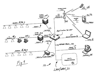
Fig. 9 shows a presently preferred embodiment of the inventive system 10
components
in three options: Option A, employing speakers 18, 36 distributed throughout
the facility in an
existing intercom system 104: Option B, employing IP speakers 98 and phones
(VOIP) 100 off
an IP PBX system 102; and Option C, employing speakers 18, 36 off an audio
amplifier 106.
Each of these options are connected to an application server 88 which includes
the above-
described application control software for selecting and initiating the alert
alarm in the selected
facility by an authorized user having access via hard wired or wireless
LAN/WAN network 20
from any one of a number of display/command entry devices such as cell phone
108, PDA 70
and/or tablet computer 72, Laptop 68, or workstation 114. In addition, the
network is linked to a
mapping database 116 for the facilities maps described above. The Network
preferably includes
a wireless access point, router or bridge 74 to permit wireless communication
from/to the input
devices 108 - 112. First (and later) Responders who have been given User
Authorization can
tap into the system to view status of affected buildings, including alert
levels and maps for
response tactical planning, via PDA, cell phone, laptop or desktop. Note that
the wireless access
device is bi-directional. That is, look-at and input to the system
(facility/building selection and
alert level triggering) can be done from the field by authorized personnel,
and conversely, the
system can send out an alert to the cell phones, pagers, PDAs, tablet
computers, laptops and
desktops of appropriate school personnel. For example, a teacher can receive a
silent alert alarm
by his/her cell phone or pager, in vibrate mode, being triggered by the system
alert selection.
In the preferred embodiment, the User computers are client computer systems
linked to
said network and each includes a CPU, a data entry device, a display device,
an operating
program, and a client user interface browser for an authorized user to access
the rapid alert
application server via said network to interact with the inventive rapid alert
application program
to trigger user-selected ones of the alarms by data signals propagated on said
network in
response to user command inputs to the application program via the Users'
client computer
systems, the User commands including inputs: for selecting sites from among a
plurality of
occupant space sites in said facility; for selecting and confirming alert
alarms from a plurality of
types of alerts, including at least two of: lockdown; evacuate, shelter in
place, all clear; and for
selecting termination of an alarm from an alarm-off button. The application
server comprises a
computer having a CPU including integrated audio and video rendering
capability or separate
CA 02579823 2007-03-08
WO 2006/034246 PCT/US2005/033594
audio and video cards, an active (RAM) memory device, a data storage device
such as a hard
drive or other permanent data storage device, the rapid alert application
program and an audio
file structure on the data storage device (for the various alarm sounds and
messages broadcast),
and a network interface device. The application server is also configured to
effect the
redundancy hand-off in the event of unit failure, or optionally, a back-up
hard drive or other
permanent memory in suitable RAID array configuration may be used to assure
system
redundancy in the event of failure of one or more of the application servers
in the system,
typically one in each building of a facility.
Optionally, a jack in an external secure, hidden enclosure accessible to the
response
tactical unit can be provided so that upon arrival at the scene, the response
unit (e.g., SWAT
team) can tap into the system to obtain a view of the event through system
status checking,
maps, and real time video and audio feeds for data to make appropriate
tactical response
decisions.
Fig. 10 shows an embodiment of the inventive system illustrating the
flexibility of the
LAN system base. The Fig. 10 embodiment has the same alarm configuration as is
shown in
Fig. 3, using a universal power supply 38, network controlled power switches
28a, 28b,
transformers 32, and alarms 36. A network-controlled pre-recorded voice
message device 120
is included in the network to trigger a particular message as an announcement
over loudspeakers
64. Wireless connection is enabled through wireless access point 74 for all
devices not
hardwired into the LAN/WAN, for example, a laptop computer 68, a PDA 70, and a
tablet
computer 72. One or more databases 116 are accessible to the system either
through LAN/WAN
or via lnternet browser access. Alternatively, such databases are resident in
the system.
Fig. 11 and 12 are related, with Fig. 11 showing the inventive system applied
to a multi-
school school district having including camera capability for real time and
archival recording
via LAN 20, and Fig. 12 showing the connectivity plan thereof. The exemplary
city School
District comprises a high school 76 having 32 cameras in place, two middle
schools 78a and
78b, having 24 and 16 cameras in place, respectively, and six elementary
schools 80a - 80f,
each having eight cameras in place. This camera embodiment uses a wireless
access port 74 to
provide real time camera views to law enforcement personnel, for example,
using wireless hand
held devices, such as PDA 70. The Wide Area Network 20 is shown in Fig. 12 as
connected to
the access ports 74a - 74d (e.g., wireless routers) to integrate with the LAN
systems of the
individual Schools 1 - 4. Camera output is also available to the LAN/WAN
computers 12 that
are a part of the permanently installed system. Each group of cameras 84a -
84f is connected to
the network through camera encoders 86a - 86d. A battery of four video
recorders 82a, 82b,
21
CA 02579823 2007-03-08
WO 2006/034246 PCT/US2005/033594
82c, and 82d are installed at a central point of the network, for example at
the central core.
Each recorder is capable of accommodating 32 cameras and preserves recordings
for about two
weeks before over-recording, unless transferred to more permanent archival
storage.
In accessing databases that are part of or linked to the inventive system, a
full menu of
options for searching and selecting specific information is included. The menu
bar can include,
for example, the following (each column to the right being a drop-down sub-
menu):
Alarms History
By School County
Clty
Named School 1
Named School 2
Haz Mat Regulations
Events
Contacts Administration
Staff
Response Personnel Police
Fire
Medical
Other
Pre-Plan Event Action Fire
Tornado
Weapon
Maps (Sites) Region
County
City School District Admin
High School
Middle School 1
Middle School 2
Elementary 1
Security
Evacuation routes
Hydrants
Staging Locations
Utilities
Tactical Plans
For example, the maps of the facilities accessible via the inventive system
include locations of
fire hydrants, locations of hazardous materials storage points, action plans
for various scenarios,
reference information for contact with various authorities, connection to
regional networks, and
access to the alarm screens.
In accord with the present invention, an exemplary facility can be accessed by
emergency response personnel as they are en route (via WiFi link to a Command
Center), or at
the site upon arrival (via a plug-in link to the inventive system, or by WiFi
to a laptop, mini
computer or hand- held PDA), or at the local facility or site admin office, so
that they can
22
CA 02579823 2007-03-08
WO 2006/034246 PCT/US2005/033594
ascertain the location of the emergency in the complex and make necessary
tactical plans for
response on the ground in real time. In this regard, the IR and US sensors,
and other presence or
locator sensors or systems (video, audio, pressure transducers, GPS, proximity
sensors and the
like) can be linked to the system to identify and/or locate the presence of
every person in the
affected area, and their movements monitored in real time during the event by
viewing on the
system screens from remote locations.
Industrial Applicability:
The inventive rapid alert system has applicability to a wide range of
facilities in or at
which the public congregates, including schools, theatres, malls, hotels,
government buildings,
courts, and the like. The system has straight-forward configurability and a
wide range of adapt-
ability to facilities having diverse physical architecture and layout. It is
unlimited as to the types
of alerts that can be programmed and configured into the applications software
that causes the
computer to control the' system and includes functionality to immediately
change the type or
status of alert in any given building or facility. Accessibility to the system
by outside responders
to detailed information, such as site maps, floor plans, and real-time camera
views of interiors
enables a new range of response capability, as well as the ability to safely
evacuate one building
at a time within the alarmed complex by simply changing the alert type, e.g.,
from lockdown to
evacuate, in a serial, timed manner to permit orderly evacuation without
creating a crowd
situation that engenders panic. The inventive system permits managers to
quickly provide
warning to their entire networked district to a pending threat by simply
selecting the appropriate
alert and building(s) or entire school system, to take the appropriate action.
Thus, the inventive
system has the clear potential of becoming adopted as the new standard for
public facilities.
It should be understood that various modifications within the scope of this
invention can
be made by one of ordinary skill in the art without departing from the spirit
thereof and without
undue experimentation. For example, the system control and operational
programs can have a
wide range of designs to provide the functionalities disclosed herein. This
invention is therefore
to be defined by the scope of the appended claims as broadly as the prior art
will permit, and in
view of the specification if need be, including a full range of current and
future equivalents.
23