Note: Descriptions are shown in the official language in which they were submitted.
CA 02579883 2009-10-06
ALIGNMENT COMPENSATOR FOR MAGNETICALLY ATTRACTED
INSPECTING APPARATUS AND METHOD
FIELD OF THE INVENTION
[00011 The present invention relates generally to an apparatus and method for
inspecting a structure and, more particularly, to an apparatus and method for
aligning
magnetically attracted probes for inspecting a structure.
BACKGROUND
[0002] Non-destructive inspection (NDI) of structures involves thoroughly
examining a structure without harming the structure or requiring significant
disassembly of the structure. Non-destructive inspection is typically
preferred to
avoid the schedule, labor, and costs associated with removal of a part for
inspection,
as well as avoidance of the potential for damaging the structure. Non-
destructive
inspection is advantageous for many applications in which a thorough
inspection of
the exterior and/or interior of a structure is required. For example, non-
destructive
inspection is commonly used in the aircraft industry to inspect aircraft
structures for
any type of internal or external damage to or flaws in the structure.
Inspection may be
performed during manufacturing of a structure and/or once a structure is in-
service.
For example, inspection may be required to validate the integrity and fitness
of a
structure for continued use in manufacturing and future ongoing use in-
service.
However, access to interior surfaces is often more difficult or impossible
without
disassembly, such as removing a part for inspection from an aircraft.
[0003] Among the structures that are routinely non-destructively tested are
composite structures, such as composite sandwich structures and other adhesive
bonded panels and assemblies. In this regard, composite structures are
commonly
used throughout the aircraft industry because of the engineering qualities,
design
flexibility and low weight of composite structures, such as the stiffness-to-
weight
ratio of a composite sandwich structure. As such, it is frequently desirable
to inspect
composite structures to identify any flaws, such as cracks, voids or porosity,
which
could adversely affect the performance of the composite structure. For
example,
typical flaws in composite sandwich structures, generally made of one or more
layers
of lightweight honeycomb or foam core material with composite or metal skins
-1-
CA 02579883 2009-10-06
bonded to each side of the core, include disbonds which occur at the
interfaces
between the core and the skin or between the core and a septum intermediate
skin.
[0004] Various types of sensors may be used to perform non-destructive
inspection. One or more sensors may move over the portion of the structure to
be
examined, and receive data regarding the structure. For example, a pulse-echo
(PE),
through transmission (TT), or shear wave sensor may be used to obtain
ultrasonic
data, such as for thickness gauging, detection of laminar defects and
porosity, and/or
crack detection in the structure. Resonance, pulse echo or mechanical
impedance
sensors may be used to provide indications of voids or porosity, such as in
adhesive
bondlines of the structure. High resolution inspection of aircraft structure
are
commonly performed using semi-automated ultrasonic testing (UT) to provide a
plan
view image of the part or structure under inspection. While solid laminates
may be
inspected using one-sided pulse echo ultrasonic (PEU) testing, composite
sandwich
structures typically require through-transmission ultrasonic (TTU) testing for
high
resolution inspection. In through-transmission ultrasonic inspection,
ultrasonic
sensors such as transducers, or a transducer and a receiver sensor, are
positioned
facing the other but contacting opposite sides of the structure to be
inspected such as
opposite surfaces of a composite material. An ultrasonic signal is transmitted
by at
least one of the transducers, propagated through the structure, and received
by the
other transducer. Data acquired by sensors, such as TTU transducers, is
typically
processed by a processing element, and the processed data may be presented to
a user
via a display.
[0005] The non-destructive inspection may be performed manually by
technicians who typically move an appropriate sensor over the structure.
Manual
scanning generally consists of a trained technician holding a sensor and
moving the
sensor along the structure to ensure the sensor is capable of testing all
desired portions
of the structure. In many situations, the technician must repeatedly move the
sensor
side-to-side in one direction while simultaneously indexing the sensor in
another
direction. For a technician standing beside a structure, the technician may
repeatedly
move the sensor right and left, and back again, while indexing the sensor
between
each pass. In addition, because the sensors typically do not associate
location
information with the acquired data, the same technician who is manually
scanning the
structure must also watch the sensor display while scanning the structure to
determine
where the defects, if any, are located in the structure. The quality of the
inspection,
-2-
CA 02579883 2009-10-06
therefore, depends in large part upon the technician's performance, not only
regarding
the motion of the sensor, but also the attentiveness of the technician in
interpreting the
displayed data. Thus, manual scanning of structures is time-consuming, labor-
intensive, and prone to human error.
[0006] Semi-automated inspection systems have been developed to overcome
some of the shortcomings with manual inspection techniques. For example, the
Mobile Automated Scanner (MAUS ) system is a mobile scanning system that
generally employs a fixed frame and one or more automated scanning heads
typically
adapted for ultrasonic inspection. A MAUS system may be used with pulse-echo,
shear wave, and through-transmission sensors. The fixed frame may be attached
to a
surface of a structure to be inspected by vacuum suction cups, magnets, or
like
affixation methods. Smaller MAUS systems may be portable units manually moved
over the surface of a structure by a technician. However, for through-
transmission
ultrasonic inspection, a semi-automated inspection system requires access to
both
sides or surfaces of a structure which, at least in some circumstances, will
be
problematic, if not impossible, particularly for semi-automated systems that
use a
fixed frame for control of automated scan heads.
[0007] Automated inspection systems have also been developed to overcome
the myriad of shortcomings with manual inspection techniques. For example, the
Automated Ultrasonic Scanning System (AUSS ) system is a complex mechanical
scanning system that employs through-transmission ultrasonic inspection. The
AUSS
system can also perform pulse echo inspections, and simultaneous dual
frequency
inspections. The AUSS system has robotically controlled probe arms that must
be
positioned proximate the opposed surfaces of the structure undergoing
inspection with
one probe arm moving an ultrasonic transmitter along one surface of the
structure, and
the other probe arm correspondingly moving an ultrasonic receiver along the
opposed
surface of the structure. Conventional automated scanning systems, such as the
AUSS-X system, therefore require access to both sides or surfaces of a
structure
which, at least in some circumstances, will be problematic, if not impossible,
particularly for very large or small structures. To maintain the ultrasonic
transmitter
and receiver in proper alignment and spacing with one another and with the
structure
undergoing inspection, the AUSS-X system has a complex positioning system that
provides motion control in ten axes. This requirement that the orientation and
spacing
of the ultrasonic transmitter and receiver be invariant with respect to one
another and
-3-
1 n L
CA 02579883 2009-10-06
with respect to the structure undergoing inspection is especially difficult in
conjunction with the inspection of curved structures.
[0008] Furthermore, manual, semi-automated, and automated scanning
systems typically are limited in the size of a structure that can be
inspected, generally
limited to areas just a few meters square and typically limited to much
smaller areas,
although some larger, more complicated systems are available. Stiffness and
weight
limitations often restrict the distance a manual, semi-automated, or automated
system
may be able to extend inspection devices over a structure for inspection.
Thus, large
composite structures may not be capable of complete inspection. For example,
contemporary inspection methods are not well suited for inspecting a Sea
Launch
payload fairing with a diameter of approximately four meters, a cylindrical
length of
approximately five meters, and an overall length of over twelve meters.
[009] Additionally, alignment of various scanning systems is typically more
complicated and requires more precision than can be provide by computer
controlled
robotic arms that are commonly used to align sensors. Alignment is especially
important when using more than one scanning probe, such as for through
transmission
ultrasonic inspection. For example, gravity, friction, and movement often
cause
misalignment of one or more probes, or two probes with respect to each other
when
used as a pair.
[0010] Accessibility to the structure requiring inspection and particular
features thereof is one consideration in choosing a non-destructive inspection
device.
Access to the structure requiring inspection may be so limited that a manual
inspection by a technician or a semi-automated or automated system is not
possible,
typically due to systems requiring access to exterior and interior surfaces of
the
structure to be inspected. For example, the backside of an inlet duct for an
Unmanned
Combat Air Vehicle (UCAV) or an F-35 has limited access for inspection.
Alignment
and positioning of sensors such as transducers is similarly complicated by
accessibility to the structure such as inaccessibility to one side of a
composite
structure. Additionally, the ability to properly align the device or devices
used for
inspection and the accessibility to do so may also be considerations in
choosing an
inspection device or system and knowing the quality and limitations thereof.
[0011] Accordingly, a need exists for an improved non-destructive inspection
device and method to inspect a structure.
-4-
CA 02579883 2009-10-06
SUMMARY OF THE INVENTION
[0012] In accordance with one aspect of the invention, there is provided an
alignment compensator for use with a magnetically coupled inspection probe.
The
alignment compensator includes a first electromagnet capable of at least
partially
altering the magnetic attraction of the magnetically coupled inspection probe,
a
variable power supply electrically connected to the first electromagnet, and a
controller interoperably connected to the variable power supply, wherein the
controller is capable of adjusting the power to the first electromagnet and,
thereby,
capable of adjusting the alteration of the magnetic attraction of the
magnetically
coupled inspection probe and correcting misalignments of the magnetically
coupled
inspection probe.
[0012a] In accordance with another aspect of the invention, there is provided
an
apparatus for ultrasonically inspecting a structure. The apparatus involves a
driven
probe structured for being disposed proximate a first surface of the
structure. The
driven probe comprises a magnet and a sensor for inspecting the structure as
the
driven probe is moved over the first surface of the structure. The apparatus
further
involves a tracking probe structured for being disposed proximate an opposed
second
surface of the structure. The tracking probe comprises a magnet for
cooperating with
the magnet of the driven probe to draw the driven and tracking probes toward
the first
and second surfaces of the structure, respectively, wherein magnetic
attraction
between the driven and tracking probes causes the tracking probe to be moved
over
the second surface of the structure in response to corresponding movement of
the
driven probe, and wherein at least one of the driven probe and the tracking
probe
comprise an alignment compensator capable of correcting misalignments between
the
sensor of the driven probe and the tracking probe.
[0012b] In accordance with another aspect of the invention, there is provided
a
probe for inspecting a structure. The probe includes a housing, a magnet
disposed in
the housing; a sensor disposed in the housing, and an alignment compensator
carried
by the housing and capable of correcting misalignments of magnetic coupling
provided by the magnet.
[0012c] In accordance with another aspect of the invention, there is provided
a
method of inspecting a structure. The method includes positioning a driven
probe
proximate a first surface of the structure and a tracking probe proximate an
opposed
second surface of the structure. The method further involves establishing
magnetic
-5-
CA 02579883 2009-10-06
attraction between the driven probe and the tracking probe such that the
driven probe
and the tracking probe are drawn toward the first and second surfaces of the
structure,
respectively and moving the driven probe along the first surface of the
structure which
causes the tracking probe to be correspondingly moved along the second surface
of
the structure. The method further includes at least partially altering the
magnetic
attraction between the driven probe and the tracking probe by introducing an
alignment compensating magnetic field to the magnetic attraction such that the
resulting magnetic attraction is asymmetrical to align the driven probe and
the
tracking probe, and transmitting ultrasonic signals into and receiving
ultrasonic
signals from the structure as the driven probe is moved along the first
surface of the
structure and the tracking probe is correspondingly moved along the second
surface of
the structure.
[0013] An improved apparatus and method for inspecting a structure, such as
a composite structure, especially a curved composite structure, compensates
for
misalignment of magnetically attracted probes. An inspection apparatus or
method
using an alignment compensator of the present invention may advantageously
improve inspection of a structure, such as continuous inspection of a large
area of a
structure, by maintaining alignment and positioning of sensing transducers
and/or
receivers. The method and apparatus of the present invention use probes
including
respective sensing elements, such as ultrasonic transducers, that are disposed
proximate the opposed surfaces of a structure. Only one of the probes need be
driven.
Either probe or both probes may include an alignment compensator for aligning
the
two probes with respect to each other. However, because only one probe need be
driven, the probes may not be accurately aligned beyond the rough alignment
provided by the magnetic coupling between the probes. Thus, the method and
apparatus of the present invention are advantageously adapted to align probes
for
inspection of structures in which a surface of the structure is relatively
inaccessible.
Further, embodiments of the method and apparatus of the present invention
permit
alignment of probes that may be suspended against and glide or contact and
ride along
the respective surfaces of the structure. Thus, embodiments of the present
invention
may reduce the necessary sophistication of the motion control system that is
otherwise
required by conventional scanning systems to maintain the ultrasonic probes in
a
predefined orientation and at a predefined spacing from the respective surface
of a
-6-
CA 02579883 2009-10-06
structure undergoing inspection and may maintain alignment between the probes
or
the sensors of the probes.
[0014] An apparatus of the present invention may include a single alignment
compensator on one probe, multiple alignment compensators on one probe, or one
or
more alignment compensators on magnetically attracted probes. Generally, an
alignment compensator is a device or system used to compensate for external
forces
acting on an apparatus that act to misalign a probe of the apparatus such that
by using
the alignment compensator, the probes of the apparatus are maintained in
alignment.
An alignment compensator may be a permanent magnet or an electromagnet. An
alignment sensor, such as a linear encoder, may be used with a controller and
a power
supply to control the magnet to align a probe with another probe.
[0015] According to another aspect of the present invention, a method of
aligning probes for inspecting a structure is provided. In this regard, the
driven probe
is positioned proximate the first surface of the structure, and the tracking
probe is
positioned proximate the opposed second surface of the structure. At least one
of the
probes includes an alignment compensator. The method of aligning the probes
includes measuring the misalignment of the sensors of the probes and
compensating
for the misalignment. Compensating for the misalignment may be performed using
a
single magnet, such as a permanent magnet. Alternatively, compensating for the
misalignment may be performed using more than one magnet. Compensating for
misalignment may include adjusting the power to an electromagnet to modify the
strength of the magnetic field produced by the electromagnet. A controller may
be
used to adjust the power to the electromagnet. The method of aligning the
probes
may include measuring the strength of a signal transmitted from one probe to
the
other or calculating the signal-to-noise ratio and adjusting the power to an
electromagnet to increase the signal or the signal-to-noise ratio. One or more
alignment compensators of the present invention may be used for aligning
probes in
different positions and for movement in any direction. As positions change and
as
movement changes, one or more alignment compensators or an alignment
compensator system may adjust or compensate for the change to maintain
alignment
of the probes.
[0016] These and other characteristics, as well as additional details, of the
present invention are further described in the Detailed Description with
reference to
these and other embodiments.
-7-
CA 02579883 2010-02-10
BRIEF DESCRIPTION OF THE DRAWING(S)
[0017] Having thus described the invention in general terms, reference will
now be made to the accompanying drawings, which are not necessarily drawn to
scale, and wherein:
[0018] Figure 1A is a schematic diagram of two probes of an apparatus
magnetically coupled to surfaces of a structure for inspection;
[0019] Figure I B is a magnified schematic diagram of two probes of an
apparatus magnetically coupled to surfaces of a structure for inspection;
[0020] Figure IC is a magnified schematic diagram of two probes of
apparatus magnetically coupled to surfaces of a structure for inspection using
ball
bearing contact members.
[0021] Figure 2A is an exploded view of a probe;
[0022] Figure 2B is yet another exploded view of the probe;
[0023] Figure 3 is an overhead perspective view of a probe;
[0024] Figure 4 is a bottom perspective view of the probe;
[0025] Figure 5A is a side perspective view of a probe including a yoke
attachment;
[0026] Figure 5B is a bottom perspective view of the probe including a yoke
attachment;
[0027] Figure 5C is yet another side perspective view of the probe including a
yoke attachment;
[0028] Figure 6 is an exploded view of a probe including ball and socket
contact members;
[0029] Figure 7 is a top plan view of a probe;
[0030] Figure 8 is a bottom perspective view of the probe;
[0031] Figure 9 is an overhead perspective view of a probe including a yoke
attachment;
-7a-
CA 02579883 2007-03-08
WO 2007/001375 PCT/US2005/033453
[0032] Figure 10 is a side view of two water bearing probes positioned across
a structure being
inspected;
[0033] Figure 11 is an orthogonal side view of the two water bearing probes
positioned across the
structure being inspected;
[0034] Figure 12 is a side view of two water bearing probes and an alignment
compensator according
to the present invention;
[0035] Figure 13 is an orthogonal side view of the two water bearing probes
and the alignment
compensator;
[0036] Figure 14 is a diagram of a ring magnet;
[0037] Figure 15 is a diagram of the ring magnet and an alignment compensator;
[0038] Figure 16A is a schematic diagram of an embodiment of a probe with a
ring magnet and an
alignment compensator with two electromagnets and an alignment compensator of
the present invention;
and
[0039] Figure 16B is a schematic diagram of an embodiment of an apparatus with
two probes, each
with a ring magnet, where one probe has an alignment compensator with two
electromagnets and an
alignment sensor of the present invention positioned across the structure
being inspected.
DETAILED DESCRIPTION
[0040] The present invention will be described more fully with reference to
the accompanying
drawings. Some, but not all, embodiments of the invention are shown. The
invention may be embodied
in many different forms and should not be construed as limited to the
embodiments described. Like
numbers and variables refer to like elements and parameters throughout the
drawings.
[0041] Alignment compensators are described with respect to an apparatus
having magnetically
attracted probes. The description of alignment compensators of the present
invention appears under the
heading Alignment Compensation in Section II and follows this description of
magnetically attracted
probes.
-8-
CA 02579883 2007-03-08
WO 2007/001375 PCT/US2005/033453
1. MAGNETICALLY ATTRACTED INSPECTION PROBES
[0042] An apparatus having magnetically attracted probes includes a driven
probe disposed proximate
a first surface of the structure and a tracking probe disposed proximate an
opposed second surface of the
structure. The driven probe is moved along the first surface of the structure.
The tracking probe follows
along the second surface of the structure in response to the movement of the
driven probe under the
magnetic attraction.
[0043] To facilitate the coordinated movement of the tracking probe in
conjunction with the driven
probe, both probes include magnets disposed to create an attractive force
between them using typical
magnetic forces of attraction. Ring magnets may be used in the probes.
[0044] A driven probe typically includes a sensing element for inspecting the
structure as the driven
probe moves along the first surface of the structure. While the sensing
element may be an x-ray detector,
a camera or the like, the sensing element is typically an ultrasonic
transducer. Typically, the tracking
probe also includes a sensing element, such as an ultrasonic transducer. The
ultrasonic transducers of the
driven and tracking probes may be an ultrasonic transmitter, an ultrasonic
receiver, or both. A sensor of a
probe, such as an ultrasonic transducer, may be positioned within a ring
magnet of a probe; thus, as the
ring magnets of the probes align the two probes on respective surfaces of the
structure, the sensors of the
probes are also aligned within the ring magnets.
[0045] To facilitate the coupling of the ultrasonic signal between the
ultrasonic transducer of the
driven probe and the structure, a couplant may be disposed between the
ultrasonic transducers and the
respective surfaces of the structure. While air or water jets may be used as a
couplant, a driven probe may
also include an inlet for fluid that is pumped between the ultrasonic
transducer and the first surface of the
structure. In this regard, the driven probe may include a housing in which the
magnet and the ultrasonic
transducer are disposed, and which defines the inlet. The housing may also
define a fluid conduit to
direct fluid flow from the inlet to a plurality of channels to disburse the
flow of fluid between the probe
and the first surface of the structure. A plurality of channels may be, for
example, a series of radially
directed recesses or a plurality of holes. The fluid conduit may be in fluid
communication with that
portion of the ultrasonic transducer of the driven probe that faces the first
surface of the structure. Thus,
-9-
CA 02579883 2007-03-08
WO 2007/001375 PCT/US2005/033453
the fluid that is pumped between the ultrasonic transducer and the first
surface of the structure may
facilitate coupling of the ultrasonic signals produced by the ultrasonic
transducer into the structure.
Likewise, the tracking probe may include an inlet for fluid that is pumped
between the ultrasonic
transducer of the tracking probe and the second surface of the structure. In
this regard, the tracking probe
can also include a housing in which the magnet and the ultrasonic transducer
are disposed, and which
defines the inlet. The housing may also define a fluid conduit to direct fluid
flow from the inlet to a
plurality of channels to disburse the flow of fluid between the probe and the
first surface of the structure.
The fluid conduit may be in fluid communication with that portion of the
ultrasonic transducer of the
tracking probe that faces the second surface of the structure. Thus,
ultrasonic signals emerging from the
structure may be effectively coupled to the ultrasonic transducer of the
tracking probe by the fluid that is
pumped therebetween. By pumping fluid between the ultrasonic transducers and
the respective surfaces
of the structure, water jets are not required such that the ultrasonic
transducers of the driven and tracking
probes may include arrays of ultrasonic transducers, thereby permitting the
rate at which the structure is
inspected to be increased and the associated inspection cost accordingly
decreased.
[00461 A probe may include a bearing contact, such as a ball and socket
bearing, a water bearing, or an
air bearing, for contacting a surface of the structure, supporting or
suspending the probe, maintaining
orientation and spacing of the probe with respect to the surface, and reducing
the frictional drag of the
probe on the surface of the structure being inspected to permit smooth
translation of the probe across the
surface of the structure. Thus, the probe may translate along the surface of
the structure. As such, the
orientation of the probe relative to the surface of the structure and the
spacing of the probe relative to the
surface of the structure may be maintained by the contact between the probe
and the surface of the
structure without requiring the complex motion control systems used by
conventional scanning systems.
This independence from the motion control systems used by conventional
scanning systems may further
reduce the cost a probe and permits the probe to be moved in a controlled
fashion over a surface of a
structure that is relatively inaccessible for a robotic arm or other
conventional motion control system.
The driven and tracking probes may also use the water or pressurized air that
is used for bearing contact
as a couplant between a sensor, such as an ultrasonic sensor, and the surface
of the structure being
-10-
CA 02579883 2007-03-08
WO 2007/001375 PCT/US2005/033453
inspected. Fluid bearings and fluid coupling are described more fully below.
However, the water or
pressurized air that is used for bearing contact need not pass in front of the
transducer to act as a couplant
but may be used only between the probe and the surface of the structure, such
as where holes or recesses
of a fluid channel are disposed around the transducer of a probe. Other
fluids, such as a gases, liquids, or
gas-liquid mixtures, may be used as couplants and/or to provide a bearing
contact between a probe and a
surface being inspected. Rather than being supported by a fluid bearing, the
probes may contact the
surface of the structure using a ball and socket bearing. When using ball and
socket bearings, a fluid,
such as water or air, may be used as a couplant between an ultrasonic
transducer of a probe and a surface
of the structure, such as bubbling water from an inlet in a probe.
[0047] Referring now to Figures 1A, 1B, and 1C, an apparatus 10 for inspecting
a structure 12 is
depicted. The apparatus 10 can inspect a variety of structures formed of
various materials. Since the
apparatus relies to some extent upon the establishment of magnetic fields
through the structure, however,
the structure is preferably non-magnetic, that is, the structure preferably
has no magnetic permeability.
Structures that may be inspected with an embodiment of an inspection device of
the present invention
may include, but are not limited to, composites, non-ferromagnetic metals
(e.g. aluminum alloy, titanium
alloy, or aluminum or titanium hybrid laminates such as GLARE or Ti/Gr), and
polymers. It should be
noted that the surfaces, and the material therebetween such as intermediate
surfaces commonly referred to
as septums, which collectively define the material through which the driven
and tracking probes are
magnetically coupled, preferably comprise a non-ferromagnetic material because
the magnetic coupling
between the probes would be diminished or eliminated by a ferromagnetic
material located between the
actuating portion and the inspecting portions.
[0048] While a portion of a relatively simple but large structural panel 12 is
depicted during the course
of an inspection in Figures 1A and 1B, a structure may be any myriad of shapes
and/or sizes. In addition,
the structure that is inspected may be used in a wide variety of applications,
including in vehicular
applications, such as in conjunction with aircraft, marine vehicles,
automobiles, space craft and the like,
as well as other non-vehicular applications, such as in conjunction with
buildings and other construction
projects. Moreover, the structure may be inspected prior to assembly or
following assembly, as desired.
-11-
CA 02579883 2007-03-08
WO 2007/001375 PCT/US2005/033453
[0049] An inspection apparatus 10 may include a driven probe 14 disposed
proximate a first surface
12a of the structure 12 and a tracking probe 16 disposed proximate an opposed
second surface 12b of the
structure. Embodiments of the present invention may also be used with an
inspection device similar to
that disclosed in U.S. Patent 6,722,202 to Kennedy directed to magnetically
attracted probes for
inspection of a structure, which is incorporated by reference. The shape and
size of an inspection probe,
and housing thereof, which may employ the present invention is not limited to
the specific embodiments
describe and disclosed herein or in the 6,722,202 patent or referenced co-
pending applications, but may
be any shape or size capable of operating in accordance with the present
invention. Driven and tracking
probes are advantageously initially positioned in alignment so as to be
directly opposed one another or
otherwise in positional correspondence with one another, as shown in Figures
1A, 1B, and 10. As shown
in Figures IA, 1B, and 10, for example, this alignment provides a linear
relationship between the probes
14, 16 such that one probe is preferably not translated or offset laterally
across the surface of the structure
12 from the other probe. As described below, this positional relationship or
correspondence between the
driven and tracking probes is maintained as the probes are moved along the
respective surfaces of the
structure and any offset or translation may be corrected by an alignment
compensator of an embodiment
of the present invention.
[0050] Each probe 14, 16 includes a ring magnet 18, 118 that may be disposed
within a housing 24,
124. The magnets of the probes magnetically attract the driven and tracking
probes toward the respective
surfaces of the structure 12. Using probes with ring magnets on opposing
surfaces of a structure also
aligns the two probes with respect to the other. By comparison, magnetically
coupled inspecting probes
using bar magnets, flat magnets, cylindrical magnets, and the like, require
configurations of magnets
and/or ferromagnetic materials to align the probes. Such configurations
typically cannot provide the
flexibility of ring magnets which may permit a tracking probe to rotate freely
with respect to a
magnetically coupled driven probe while maintaining alignment of ultrasonic
transducers located within
the center of the ring magnets in the driven and tracking probes. Magnetically
coupled probes employing
embodiments of the present invention may alternatively, or in addition, use
magnets and/or ferromagnetic
materials to provide alignment and/or magnetic attraction between probes.
While each probe may include
-12-
CA 02579883 2007-03-08
WO 2007/001375 PCT/US2005/033453
any number of magnets, each probe need only include one ring magnet which
reduces the size, weight,
cost, and complexity of the probes. Magnets of the illustrated probes may be
ring magnets formed of
neodymium iron boron, which have advantageously have greater magnetic flux
(around 12,000 gauss)
than standard ceramic or ferrite magnets (around 3,900 gauss). Further
embodiments of inspection probes
and alignment compensators of the present invention may include magnets of
different material, such as
Samarium Cobalt or Alnico and/or electromagnets or other magnetic coupling
means. The term "magnet"
as used herein is inclusive of electromagnets. Alignment compensators of the
present invention and
inspection probes may further comprise magnetic shunting mechanisms to control
the magnetic flux of
the magnetic couplings, a non-limiting example being rare earth metal switched
magnetic devices
disclosed in U.S. Patent 6,180,928. While various types of ring magnets may be
used, the driven and
tracking probes of one embodiment include permanent ring magnets, such as
NdFeB ring magnets. The
size of ring magnets for both the driven and tracking probes may be dependent,
at least in part, upon the
weight of the respective probes, the thickness of the structure undergoing
inspection, and the material that
forms the structure undergoing inspection. For example, a ring magnet of a
probe may be 4 inches in
diameter and 1 inch in height with a magnetic flux of 3.9k Gauss across the
surface of the ring magnet if
the magnet is a standard ferrite ring magnet or 12k Gauss if the magnet is an
NdFeB ring magnet.
Additionally, driven and tracking probes may include ring magnets having
either the same or different
sizes.
[0051] Although ring magnets may be used independently to positionally align
probes, rotational
alignment of probes may be enhanced by incorporating at least one additional
magnet or ferromagnetic
material to at least one of the probes. For example, if one of the probes
includes ferromagnetic material,
such as a plug of ferromagnetic material, the other probe may include an
additional magnet, or possibly
an alignment compensator, positioned such that the probes are properly
positioned with respect to one
another when the ferromagnetic plug and the additional magnet are aligned
since the ferromagnetic plug
and the additional magnet of the other probe will be attracted to one another
when these elements are
properly aligned to position the probes with rotational alignment. Similarly,
if the probes each include
two additional magnets, where the two additional magnets of each probe have
opposite polarities, when
-13-
CA 02579883 2007-03-08
WO 2007/001375 PCT/US2005/033453
the probes are misaligned, the additional magnets of the probes would be
repelled and produce a rotation
of the probes until the additional magnets of the probes align with the
additional magnets of the other
probe that are of the opposite polarity. As such, these types of additional
magnets and ferromagnetic
materials may be used as rotational alignment keys for probes.
[0052] In determining the type of magnets, the weight of the magnets, the
surface area of the magnets
and the increased demagnetization effects attributable to the cylindrical
length to diameter ratio and/or
cylindrical length to radial width ratio of the magnet are typically taken
into consideration. In this regard,
magnets that are relatively thin and flat may have a substantial surface area
so as to generate significant
magnetic flux. However, these magnets are generally inefficient since they
suffer from increased
demagnetization effects due to their relatively small cylindrical length to
diameter ratio and/or cylindrical
length to radial width ratio relative to thicker, more rod-like ring magnets
having a smaller surface area.
[0053] At least one of the probes 14, 16, usually the driven probe, includes a
sensing element 32, 132
for inspecting the structure 12 as the probe is moved over the respective
surface of the structure. Further
with respect to Figures 2A, 2B, 3, and 4, the sensing element 32, 132 is
positioned in the ring magnet 18,
118 within a central cavity 40, 140 of a housing 24, 124 A sensing element may
be a camera, an x-ray
detector, pulse echo sensor, or the like , but generally is an ultrasonic
transducer, such an ultrasonic
transmitter and/or an ultrasonic receiver. For example, the ultrasonic
transducer may be a 1 MHz
immersion transducer from Agfa/Krautkramer of Lewistown, PA.
[0054] Such probes provide for through transmission ultrasonic (TTU)
inspection. Ultrasonic signals
are transmitted into the structure by the ultrasonic transducer of one probe
and received by the ultrasonic
transducer of the other probe to detect flaws, including cracks, voids and/or
porosity. However, only one
probe needs to include a sensing element 32, 132 for inspection from one side
of the structure 12, such as
for pulse echo (PE) inspection.
[0055] To facilitate the coupling of ultrasonic signals between ultrasonic
transducer(s) of the driven
and/or tracking probes 14, 16 and the structure 12, a couplant may be used.
While air or water jets may
be used as a couplant, the driven and/or tracking probes 14, 16 and, in
particular, the respective housings
-14-
CA 02579883 2007-03-08
WO 2007/001375 PCT/US2005/033453
may include an inlet 22, 122 for fluid such as water or air, that is pumped
between an ultrasonic
transducer and a respective surface 12a, 12b of the structure.
[0056] As shown in Figures 2A, 2B, 3, and 4, the housing 24 includes a fluid
conduit 23 connecting
the fluid inlets 22 to fluid dispersion channels 42, such as recesses or
holes. The fluid conduit 23 and/or
the fluid dispersion channels 42 may also be in fluid communication with a
portion of the sensing element
32, such as an ultrasonic transducer, that faces a surface of the structure 12
proximate the probe. The
sensing element 32, such as an ultrasonic transducer, may be recessed within
the housing 24. Thus, fluid
that is introduced through the inlet 22 flows through the fluid conduit 23,
including an internal channel,
defined by the housing 24 and effectively fills the gap between the ultrasonic
transducer and the surface
of the structure 12. Advantageously, the fluid flows smoothly over and between
the ultrasonic transducer
and the surface of the structure with no bubbles, cavitation or turbulence
that could otherwise
detrimentally affect the signal to noise ratio.
[0057] The fluid is supplied from a reservoir connected to the inlet 22. A
tube press fit around the inlet
22 leads to a flow control valve, which may include a bleed value to maintain
constant pressure and
prevent excess pressure or volume of fluid.
[0058] As shown in Figures 2A and 2B, a cap 25 secures the ring magnet 18 into
a cup formed in the
housing 24. The bottom of the housing 24 may also include channels 42 to
direct the flow of fluid to
create a fluid bearing. If the fluid is also used as a couplant, the fluid
passes over an sensing element 32,
such as an ultrasonic transceiver, affixed within the central cavity 40 of the
housing 24, and out through
the channels. The shape and size of the housing does not dictate the present
invention, but may be
adapted to incorporate or facilitate features of the present invention. For
example, the shape and size of
the housing 24 shown in Figures 2A and 2B are dictated to provide support for
the ring magnet 18 and
fluid inlets 22. The shape is further dictated to provide smooth edges which
may be proximate a surface
of a part to avoid the housing interfering with the operation of embodiments
of the present invention.
[0059] A handle or other connector, such as a yoke attachment 30, is used for
controlling a driven
probe 14 across a surface of a part. Figures 5A, 5B, 5C, and 9 show a yoke
attachment 30 for a manual,
semi-automatic, or robotic arm extension.
-15-
CA 02579883 2007-03-08
WO 2007/001375 PCT/US2005/033453
[0060] In operation, the driven and tracking probes 14, 16 are disposed
proximate first and second
surfaces 12a, 12b of the structure 12. As shown in Figures 1A, 1B, and 1C the
driven and tracking
probes may advantageously be disposed in contact or bearing contact with the
structure. Bearing contact
may provide suspension of a probe above a surface of a structure, such as by a
fluid bearing and/or a ball
and socket bearing. For example, a water bearing or an air bearing may support
a probe on a structure.
To facilitate contact of the probes with the respective surfaces of the
structure and to avoid any
undesirable damage or other marring of the respective surfaces of the
structure as the result of contact
with the probes, the driven and tracking probes can each also include at least
one contact member 28,
such as a ball and socket bearing or a skid, which can be used in conjunction
with or independently from
a fluid bearing. Skids may be beneficial for fluid bearing probes such as to
prevent damage or marring of
a surface of a structure under test when initially placing a probe on the
structure or magnetically coupling
two probes on opposite sides of the part, particularly when the fluid bearing
may not be in use, such as
before fluid is provided to the probe or after fluid is stopped flowing to the
probe. Alternatively, a probe
may include one or more ball and socket bearings that contact the respective
surface of the structure and
that permit the probe to ride therealong when not using a fluid bearing. Fluid
bearings, such as water
bearing and air bearings, and ball bearings may be used to maintain the
spacing and orientation of the
probes. Water, air, or ball bearings may be used to reduce the fiction between
the inspection probe and
the surface of the structure under inspection, such as to displace the probe
from contacting the surface of
the structure using hydraulic or pneumatic flotation or a hydrostatic bearing.
Further, use of bearing
contact between the inspection probe and the surface of the structure may
prevent scratching of soft skins
or denting of panels of the skins. Use of bearing contact may also provide
smooth translation of an
inspection probe over the surface of a structure to allow an inspection probe
to maintain an intended
direction, maintain alignment of transducers and/or receivers in inspection
probes, and allow continuous
scanning of a surface regardless of size, smoothness, or flatness of the
surface.
[0061] A fluid bearing, also referred to as a fluid dynamic bearing, may be
created by pumping a thin
layer of fluid between the surface of a housing for a probe which is adjacent
to the part under inspection
and the surface of the part adjacent to the probe. The pressure from the
magnetic attraction of the probe
-16-
CA 02579883 2007-03-08
WO 2007/001375 PCT/US2005/033453
towards the part on the fluid and the pumping of the fluid into the compressed
space creates the fluid
bearing. The housing for the probe rests upon the thin layer of fluid between
the probe and the surface of
the part. Although fluid bearings typically use a seal to maintain hydrostatic
fluid in a defined space,
pumping fluid into the space for the fluid bearing at the rate that the fluid
escapes from the fluid bearing
maintains sufficient volume and pressure of fluid in the space to achieve a
fluid bearing. As described
herein, a fluid used for a fluid bearing may also be used to provide a
couplant between a sensor and a
surface of the part under inspection. For example, the water of a water
bearing may flow between the
transmitting end of an ultrasonic transducer and the adjacent surface of the
part under inspection and then
may flow between a surface of the housing for the probe and an adjacent
surface of the part under
inspection to produce a fluid bearing.
[0062] Figure 6 is a bottom perspective view of an exploded diagram of a probe
including ball and
socket bearings. A housing 124 may include a central cavity 140 to retain a
sensor 132 such as an
ultrasonic transducer. By comparison to the embodiment of Figure 2B, the
embodiment of Figure 6 has
an inverted, compressed housing 124, disposed around a ring magnet 118, with
two caps 125, 127 and
ball and socket bearings 128. Alternatively, a ring magnet may be retained in
a housing with a cap
integrally formed by the housing or with a recess for the ring magnet such
that the housing does not
require a cap or caps to retain the ring magnet. The ball and socket bearings
128 may include spherical
bearings 144 each housed by a socket 146. The sockets 146 may be attached to
the housing in ball and
socket support members 148 or may be integrally connected to and formed by the
housing. In one
embodiment, three or more spherical ball are held in corresponding sockets to
facilitate the rolling
inspection of two magnetically attracted probes on opposite surfaces of a
structure.
[0063] Figure 7 is a top plan view of a probe. Figure 8 is a bottom
perspective view of a probe. The
housing 124 defines a central cavity 140 in which a sensor 132 such as an
ultrasonic transducer is
disposed. The housing 124 also includes an outer perimeter in which the
sockets 146 are integrally
formed and into which respective balls 144 are inserted. Between the outer
perimeter and central collar of
the housing 124 is disposed a ring magnet. A first cap 125 and a second cap
127 retain and/or secure the
ring magnet within the housing 124. A fluid inlet 122 may be attached to,
disposed in, or otherwise
-17-
CA 02579883 2007-03-08
WO 2007/001375 PCT/US2005/033453
formed by the housing to permit the flow of fluid through the inlet and the
housing. In a ball bearing
embodiment, fluid such as water may be used as a couplant between an
ultrasonic transducer and the
surface of the structure being inspected. An inlet 122 may be part of a fluid
conduit 123 that permits the
flow of fluid through the housing 124.
[0064] Figure 9 is an overhead perspective view of a probe including a yoke
attachment. The probe
may include, or have attached, a handle or other connector, such as a yoke
attachment 130, for controlling
and driving the probe across a surface of a part.
[0065] By permitting contact or bearing contact between the driven and
tracking probes 14, 16 and the
respective surfaces 12a, 12b of the structure 12, and by the magnetic
attraction between the ring magnets
of the probes, the position and orientation of the probes and, more
particularly, the sensing elements, such
as the ultrasonic transducers, of the probes may generally be maintained
without requiring a complex
motion control system or other type of positioning system. Additionally, the
contact or bearing contact
between the driven and tracking probes and the respective surfaces of the
structure may maintain a
consistent spacing between the respective sensing elements, such as the
respective ultrasonic transducers,
and the structure, without requiring complex motion control systems or other
positioning systems.
Further, the use of magnetically attracted inspection probes permits
continuous scanning techniques such
as manual scanning of an entire surface by comparison to point-by-point or
grid-type inspection methods
that may commonly be used for manual, semi-automated, and automated scanning
systems. Because
magnetically attracted probes preferably maintain positioning of the
transducers, an inspection area may
be as large as the entire structure, and a single operator may be able to
inspect the structure.
[0066] The operation of the apparatus 10 is described in conjunction with
driven and tracking probes
14, 16 configured to conduct a through transmission ultrasonic inspection.
However, the driven and
tracking probes may be used in other manners as described below. By way of
example of the operation of
one embodiment of the driven and tracking probes, however, the driven and
tracking probes are disposed
proximate to and generally in contact with the opposed first and second
surfaces 12a, 12b of a structure
12 while maintaining position and magnetic attraction between the probes.
Fluid, such as water, may then
be bubbled through the inlet 22 of each probe and between the ultrasonic
transducers and the respective
-18-
CA 02579883 2007-03-08
WO 2007/001375 PCT/US2005/033453
surfaces 12a, 12b of the structure 12. Bearing contact, such as a fluid
bearing, including liquid and air
bearings, or ball bearings may be used to maintain adequate spacing between
the probe and the surface of
the part under inspection. In such a manner, the bearing contact may be used
to prevent the probe from
contacting and possibly damaging the surface of the part. Further, the bearing
contact provides the probe
the ability to translate along the surface of the part for continuous
scanning. The ultrasonic transducers
are activated such that the ultrasonic transducer of one probe, emits
ultrasonic signals into the structure.
A drive element, such as a voltage or current source connected to a
computerized control program, is
generally associated with the ultrasonic transducer of the driven probe so as
to actuate the ultrasonic
transducer to emit the ultrasonic signals. This drive element may be co-
located with the driven probe or
may be remote therefrom and electrically connected to the ultrasonic
transducer. Correspondingly, the
ultrasonic transducer of the other probe, receives the ultrasonic signals
originally transmitted by the
ultrasonic transducer of the driven probe following the propagation of the
ultrasonic signals through the
structure.
[0067] While the ultrasonic signals are transmitted through the structure 12
and fluid is passed over the
respective ultrasonic transducers, the driven probe 14 is moved along the
first surface 12a of the structure.
While the motive force required to move the driven probe along the first
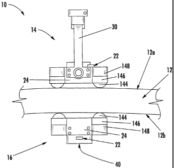
surface of the structure may be
applied in various manners, the driven probe of the illustrated embodiment
includes a handle that may be
engaged by a robotic arm or the like. As known to those skilled in the art,
the robotic arm can be
controlled by a motion control system or other positioning system so as to
controllably move the driven
probe in a predefined manner and in accordance with a defined pattern along
the first surface of the
structure.
[0068] As a result of the magnetic attraction established between the driven
and tracking probes 14, 16
and, more particularly, between the magnets 18, 118 of the driven and tracking
14, 16 probes, the tracking
probe 16 follows the driven probe 14. Thus, the tracking probe 16 moves so as
to remain in a preferably
aligned, opposed position relative to the driven probe 14. Accordingly, the
tracking probe 16 can be
disposed proximate to and can ride along a second surface 12b of a structure
that may be relatively
inaccessible, such as the interior of a cylindrical structure or other
structure having a closed shape.
-19-
CA 02579883 2007-03-08
WO 2007/001375 PCT/US2005/033453
[0069] By passing fluid between the ultrasonic transducer and the respective
surface of the structure
12, the ultrasonic signals are effectively coupled into and/or out of the
structure. Moreover, while a single
ultrasonic transducer is depicted in Figures 2A, 2B, and 6, driven and/or
tracking probes 14, 16 may
include an array of ultrasonic transducers to increase the inspection area
since the coupling provided by
the fluid permits inspection in an ultrasonic array mode, thereby increasing
the speed with which the
inspection is performed and potentially reducing the cost associated with the
inspection.
[0070] A tracking probe may include a larger diameter transducer than the
transducer of a driven
probe. Using a larger tracking probe transducer enables a more uniform signal
over a larger area than
would a corresponding smaller transducer. Thus, using a larger transducer in
the tracking probe may
minimize the effect of small misalignments between the driven probe and
tracking probe, and transducers
thereof, such as misalignments due to discontinuities in the surfaces of the
structure, positional lagging of
the tracking head, and gravitational offset.
II. ALIGNMENT COMPENSATION
[0071] The driven and tracking probes may be misaligned or translationally
offset for reasons such as
discontinuities in the surface of the structure, positional lagging of the
tracking head, and gravitational
offset of the tracking head. For example, when probes are in a vertical or
near-vertical position with
respect to a gravitational force, the weight of the tracking probe of the
magnetically coupled devices may
cause the tracking probe to hang down relative to the driven probe. In this
instance, the magnetic
coupling is not strong enough to hold the centers of the driven and tracking
probes perfectly aligned.
When transducers of driven and tracking probes are misaligned, the signal
transmitted through a part
under inspection and received by a receiving probe, typically the tracking
probe, may be diminished.
When scanning in horizontal or near-horizontal positions with respect to a
gravitational force, the probes
may be aligned with acceptable accuracy for a strong signal to be transmitted
from one probe, propagate
through the part under inspection, and be received by the other probe.
Further, for example, at higher
scanning speeds, a tracking probe may lag behind the driven probe due to the
strength of magnetic
coupling and frictional forces, causing transducer misalignment between the
probes.
-20-
CA 02579883 2007-03-08
WO 2007/001375 PCT/US2005/033453
[0072] One option to account for misalignments between driven and tracking
probes as described, may
be to provide a larger transducer area in one of the probes, typically the
tracking probe, to provide a
greater area to receive a signal from a transmitting probe. Another
possibility to account for
misalignments may be to mount one of the transducers off-center. For example,
in the case of a gravity-
driven misalignment, the driven probe may have its transducer lowered relative
to the transducer of the
tracking probe to be in alignment with the transducer of a tracking probe.
Similarly, at higher scanning
speeds, the transducer of the driven probe may be moved in the trailing
direction until it is aligned with
the transducer of the tracking probe. However, adapting the position of a
transducer may limit scan
capabilities such that data may only be taken in one scan direction or one
orientation, or the off-center
mounting of a transducer to be made adjustable to account for different scan
angles and speeds although
the design of the probes would become more complex. Alternatively, or in
addition, a tracking probe
advantageously includes an alignment compensator of an embodiment of the
present invention to correct
misalignments between the tracking probe and the driven probe. For example, an
embodiment of an
alignment compensator of the present invention may compensate for off-
centering and/or lagging of
magnetically coupled devices caused by gravity or rapid movement of a driven
probe.
[0073] Figure 10 is a side view of two water-bearing probes positioned across
a structure being
inspected. As can be seen by the probes 214, 216 magnetic coupled on opposing
sides of a structure 212
under inspection, the tracking probe 216 hangs lower than the driven probe 214
because the magnetic
coupling between the driven probe 214 and the tracking probe 216 does not
compensate or counteract the
force of gravity on the tracking probe 216. Specifically, the top of the
driven probe 214 is marked by a
line 215 which is higher than the top of the tracking probe 216 which is
marked by a lower line 217. In
one embodiment, the probes 214, 216 in Figure 10 have as much as a 3/s inch
vertical difference between
the tops of the probes, respectively, although this offset will vary based
upon the weight of the probes, the
strength of the magnets, etc. As a result, the ultrasonic signal is attenuated
by the offset in passing
between the transducers 241 of the probes 214, 216. The result can be seen as
a partial or low signal 252
due to the off-centering of the probes.
-21-
CA 02579883 2007-03-08
WO 2007/001375 PCT/US2005/033453
[0074] Figure 11 is an orthogonal side view of the two water-bearing probes in
Figure 10. By
comparison to the view shown in Figures 10, the probe 214 which is visible in
Figure 11 is the driven
probe 214. The tracking probe is behind the structure 212 under inspection.
The top of the driven probe
214 is indicated by a line 215 by comparison to a lower line 217 which marks
the top of the tracking
probe 216.
[0075] Figure 12 is a side view of two water-bearing probes and an alignment
compensator according
to the present invention. Unlike the probes 214, 216 in Figures 10 and 11, the
probes 214, 216 in Figure
12 are aligned with the tops of the probes at the same height indicated by a
line 215. An alignment
compensator 260 has been added to the driven probe 214 to force the tracking
probe 216 up to align with
the driven probe 214. Accordingly, an improved signal 254 may be acquired
between the transducers 241
of the probes 214, 216.
[0076] Figure 13 is an orthogonal side view of the two water-bearing probes
and the alignment
compensator. Figure 13 relates to Figure 12 as Figure 11 relates to Figure 10.
The alignment
compensator operates to raise or push up the tracking probe 216 to align the
driven probe 214 and the
tracking probe 216 such that the tops of both of the probes 214, 216 are
aligned as indicated by a single
line 215.
[0077] An alignment compensator of the present invention may be a permanent
magnet or an
electromagnet which modifies the magnetic field between the two opposing
probes or, more particularly,
between the two ring magnets of the opposing probes. Ring magnets used to
produce the magnetic
coupling between the probes have approximately uniform magnetic field
strengths across their flat faces,
referring to the respective surfaces of the ring magnets adjacent to the
opposing sides of the structure
against which the probes are respectively supported. As describe below, an
alignment compensator
according to the present invention may produce an opposing magnetic field
relative to the face of the ring
magnet of the driven probe. By way of example, with respect to the driven 214
and tracking 216 probes
of Figure 12 in which the tracking probe would otherwise be displaced
downwardly with respect to the
driven probe, the alignment compensator 260 is located on the lower side of
the ring magnet of the driven
probe 214 to push or oppose the magnetic field created by the lower portion of
the ring magnet of the
-22-
CA 02579883 2007-03-08
WO 2007/001375 PCT/US2005/033453
driven probe 214, that is, the portion of the ring magnet proximate the
alignment compensator, thereby
reducing the effective field strength resulting from the lower portion of the
ring magnet of the driven
probe. As such, the ring magnet of the tracking probe 216 will be more greatly
attracted towards the
upper portion of the ring magnet of the driven probe 214, thereby overcoming
the tendency of the
tracking probe to otherwise be displaced downwardly relative to the driven
probe. In this embodiment,
the magnetic field strength of the magnet of the alignment compensator 260
creates a force which pushes
the tracking probe away from the alignment compensator, or more particularly,
opposes the strength of
the portion of the ring magnet of the driven probe 214 adjacent to the
alignment compensator 260.
Because the magnet of the alignment compensator 260 is positioned on a side or
outside of the ring
magnet of the driven probe 214, and as a result of the attractive force of the
ring magnets, the ring magnet
of the tracking probe 216, and correspondingly the tracking probe 216 itself,
moves parallel to the ring
magnet of the driven probe 214, and does not lift off or separate from the
surface of the part under
inspection.
[0078] Figure 14 is a diagram of a ring magnet. The diagram in Figure 14
shows, as a non-limiting
example, the measured magnetic fields, using a directional gauss meter, on the
surface of the ring magnet
of a driven probe which would be adjacent to a surface of a structure under
inspection. At the surface of
the ring magnet, 3.9k gauss is uniformly recorded around the circumference of
the surface of the ring
magnet. The magnetic field strength is measured at approximately 90% of the
surface field strength at
one inch in front of the surface of the ring magnet.
[0079] Figure 15 is a diagram of the ring magnet and an alignment compensator
of the present
invention. The presence of the magnet of the alignment compensator provides a
field, represented by
negative field strength numbers, which opposes the field strength of the ring
magnet. The magnetic force
of the magnet of the alignment compensator tends to lift or push, as the
situation may be, the ring magnet
of the tracking probe relative to the ring magnet of the driven probe. In a
vertical position, the alignment
compensator of this embodiment would generally be disposed lower than the ring
magnet and would
therefore lift the tracking probe. In a horizontal position with rapid
scanning, the alignment compensator
of this embodiment would generally be displaced in the trailing direction from
the ring magnet and would
-23-
CA 02579883 2007-03-08
WO 2007/001375 PCT/US2005/033453
accordingly push the tracking probe forward to match the velocity of the
driven probe. Magnetic field
strengths recorded at the surface of the alignment compensator coplanar with
the surface of the ring
magnet are approximately 3.8k gauss to 4.4k gauss. The negative measurement
numbers represents an
opposite magnetic force as that of the ring magnet.
[0080] As described, the magnet of an alignment compensator may be a permanent
magnet or an
electromagnet. If the magnet of an alignment compensator is an electromagnet,
adjusting the electric
current through the electromagnet will modify the strength of the alignment
compensator, allowing
centering adjustment of driven and tracking probes for scanning at various
angles and/or various speeds.
As described below, the probe of this aspect of the present invention may
include an alignment sensor
used to control the magnetic field generated by the electromagnet of the
alignment compensator. For
single orientation, constant angle scans and single orientation, fixed
velocity scans, a permanent magnet
may be used in an alignment compensator to simplify the components and
operation of an alignment
compensator. Further, in different applications or different scanning
situations, a permanent magnet or an
electromagnet of an alignment compensator may be changed for a different
magnet such as when the
scanning angle or scanning velocity changes. An alignment magnet housing may
be used to support
and/or retain different permanent magnets or electromagnets of an alignment
compensator.
[0081] Figure 16A is a schematic diagram of an embodiment of a probe with a
ring magnet, an
alignment compensator with two electromagnets on opposite sides of the ring
magnet and an alignment
sensor. Figure 16B is a schematic diagram of an embodiment of an apparatus
with two probes, each with
a ring magnet, where one probe has an alignment compensator with two
electromagnets and an alignment
sensor, or motion and/or directional sensor, positioned across the structure
being inspected. The
arrangements or systems presented in Figures 16A and 16B may be advantageously
useful in high-rate
inspection situations where the alignment compensator may be used to correct
misalignments between the
driven probe and the tracking probe. For example, an alignment sensor, such as
a linear encoder 270 or
other directional sensor, may be used to identify the speed of the driven
probe and possibly also the
direction of movement of the driven probe. At low scan speeds, no compensation
may be necessary for
the alignment, or more specifically the misalignment, between a driven probe
and a tracking probe and, as
-24-
CA 02579883 2007-03-08
WO 2007/001375 PCT/US2005/033453
such, the electromagnets are not energized. However, for high-rate
inspections, there may be sufficient
lag such as caused by frictional and/or inertial drag on the tracking probe to
produce a noticeable lag of
the tracking probe, thereby decreasing the received inspection signal. Thus,
for high-rate inspections, an
alignment compensator system may be used to prevent tracking probe lag, such
as by placing
electromagnets of an alignment compensator on opposing sides of the ring
magnet of the driven probe.
The driven probe may include, in addition to the ring magnet 218, two
electromagnets 262 which may be
independently operated to provide correctional alignment between the driven
probe and a tracking probe.
The electromagnets 262 may be placed on the forward and trailing directional
sides of the ring magnet
218. Depending upon the particular direction of motion, these electromagnets
262 of the alignment
compensator system may be powered to push the tracking probe to keep up with
the driven probe. For
example, although preferably the scanning would be performed in the forward or
trailing directions, the
electromagnets may be powered at varying amounts using a variable power supply
to control
misalignments of the driven and tracking probes along directions not
coordinated with the forward and
trailing positions of the electromagnets 262 of the alignment compensator
system. Additional
electromagnets 262 may be positioned at various other locations around a ring
magnet 218 of the driven
probe to provide for additional correction between driven and tracking probes
moving in any number of
directions. By way of example, a signal sensor of an alignment compensator
system may monitor the
TTU signal that is transmitted through the part and communicate with a
controller to adjust a variable
power supply to alter the performance of an alignment compensator based upon
the measured TTU signal,
such as to adjust the correction by the alignment compensator to improve the
signal strength, to increase
the measured signal by correcting misalignments between driven and tracking
probes. For example, if a
signal sensor of an alignment compensator system identifies that the signal
strength is reduced in a
manner inconsistent with attenuation due to a flaw in the structure, the
signal sensor may indicate to the
controller, in coordination with an alignment sensor such as a linear encoder,
to increase or decrease the
power to an electromagnet to correct for misalignment between driven and
tracking probes. Similarly, a
magnetic indexing system such as disclosed in co-pending application entitled
"Control System and
Method for Magnetic Indexer for High Accuracy Hole Drilling," published on
November 12, 2003, as
-25-
CA 02579883 2009-10-06
U.S. Patent Appl. Pub. No. 2003/0210027, may be used by a controller of an
alignment compensating system for aligning magnetically coupled probes using
an
alignment compensator of the present invention. Where an alignment compensator
includes more than one electromagnet, a controller may turn off the power of
one or
more of the electromagnets to adjust the performance of the alignment
compensator.
[00821 The alignment sensor may be a linear encoder 270, an optical sensor,
directional sensor, or wheel encoder that is mounted to the control head to
provide
instantaneous direction and/or speed information which may be used by the
controller
268 to modify and adjust the power of electromagnets 262 in an alignment
compensator system. Information from the alignment sensor may be provided to
an
encoder/decoder 266, also referred to simply as a decoder, which defines data
transmitted to a controller 268 which adjusts and modifies the power of the
electromagnets 262, and, thus, the alignment compensator, by controlling the
power
supply 264 for the electromagnets 262. For example, as a driven probe moves in
a
forward direction, the alignment sensor may identify the forward motion of the
driven
probe and provide the information to the decoder 266 which may provide data to
the
controller 268 to allow the controller 268 to adjust the power supply in the
electromagnets 262 to decrease the power to the forward electromagnet in the
alignment compensator system and increase the power to the trailing
electromagnet in
the alignment compensator system to push the tracking probe in an amount
proportional to the forward speed of the driven probe to correct for
misalignment
between the driven and tracking probes. An alignment sensor of an embodiment
of
the present invention may be adapted to be capable of providing information
directly
to a controller without using a decoder 266. An alignment sensor of an
embodiment
of the present invention may also be adapted to provide both direction and
speed
information about the driven probe to provide the alignment compensator system
the
ability to control power to one or more electromagnets based on the speed
and/or
direction of the driven probe. An alignment compensator, or an alignment
compensator system, may be configured differently so long as the alignment
compensator, or alignment compensator system, compensates for. misalignments
between driven and tracking probes. For example, instead of having an
electromagnet
of an alignment compensator
-26-
CA 02579883 2007-03-08
WO 2007/001375 PCT/US2005/033453
destructively interfere with a portion of a ring magnet, an electromagnet of
an alignment compensator
could constructively interfere to pull, instead of push, a tracking probe.
[0083] Many modifications and other embodiments of the invention will come to
mind to one skilled
in the art having the benefit of the teachings presented in the foregoing
descriptions and the associated
drawings. Therefore, the invention should not be limited to the specific
embodiments disclosed. Specific
terms are used in a generic and descriptive sense only and not for purposes of
limitation.
-27-