Note: Descriptions are shown in the official language in which they were submitted.
CA 02580098 2007-03-01
SEPARATION OF TAR FROM SAND
FIELD OF THE INVENTION
[0001] This disclosure relates generally to a method for extracting
hydrocarbon
"bitumen" from rocks, clay, and mined oil sand.
BACKGROUND OF THE INVENTION
[0002] Throughout the world, considerable oil reserves may be found locked in
the
form of tar/oil sand, also known as bitumen sand. Bitumen, which is a viscous
hydrocarbon, is trapped between the grains of sand, clay, and water. Because
the
recovery of bitumen from the sand may provide an increasingly valuable
commercial energy source, processes for extracting and refining bitumen have
long been investigated.
[0003] One method for recovering tar sand is by mining. In these operations,
surface or shallow oil sands are open pit mined. The cost of mining increases
with
the depth of burial of the formation. At some point, the amount of overburden
and
the cost of its removal becomes too great. These deeper deposits have recently
begun to be exploited by drilling wells through the overburden. In some cases,
the
bitumen behaves as a fluid under reservoir conditions, and may flow into the
well
for production by conventional means. However, in other cases, the bitumen is
either too viscous or is too solidified, and may not flow. To recover these
deposits, steam or other heat sources may be introduced into the tar sand
formation
to liquefy the bitumen. Recently, a technique of drilling closely spaced
horizontal
wells that allow a controlled passage of steam therebetween has become
popular.
After months of steaming, the molten tar flows into collection wells for
recovery.
So-called Steam Assisted Gravity Drainage is one such technique.
[0004] In Alberta, the tar sands underlie a wide expanse of undeveloped and
environmentally sensitive areas in the north of the province. Drilling wells
CA 02580098 2010-03-01
inevitably creates large amounts of overburden and tar sand cuttings.
Currently,
tarred cuttings must be hauled to either existing mining operations or
permitted
disposal sites. Therefore, processes that separate tar from sands at the drill
site and
allow delivery of sands clean enough for on-site disposal may reduce the cost
of
drilling.
100051 Similar problems may occur when attempting to remove tar from drilled
cuttings as those encountered when trying to recover tar from mined sand.
However,
when removing tar from drilled cuttings, surfactants, substances present in
drilling
fluid, and substances otherwise used to facilitate tar removed during the
drilling
process may contaminate the drilled cuttings. Such substances may cause
environmental concerns if not removed from the drilled cuttings prior to
disposal.
[00061 Currently, extraction of the bitumen from oil sand and drilled cuttings
may be
accomplished though a number of different processes. One process involves
mixing
the oil sand with hot water, an example of which is disclosed in U.S. Patent
No.
5,626,741. In the hot water extraction process, oil sands are first
conditioned in large
conditioning drums or tumblers with the addition of NaOH and water at a
temperature of about 85 C. The tumblers provide means for steam injection and
physical action to mix the resultant slurry vigorously, causing the bitumen to
be
separated from the oil sands, and then aerated to form bitumen froth.
[0007] The slurry from the tumblers is then screened to separate out the
larger debris
and passed to a separating cell where settling time is provided to allow the
slurry to
separate. As the slurry settles, the bitumen froth rises to the surface and
the sand
particles and sediments fall to the bottom. A middle viscous sludge layer,
termed
middlings, contains dispersed clay particles and some trapped bitumen that is
not
able to rise due to the viscosity of the sludge. Once the slurry has settled,
the froth is
skimmed off for froth treatment and the sediment layer is passed to a tailings
pond.
2
CA 02580098 2007-03-01
M
The middlings are often fed to a secondary flotation state for further bitumen
froth
recovery.
10008] Bitumen froth contains bitumen, solids, and trapped water. The solids
that are
present in the froth are in the form of clays, silt, and sand. From the
separating cell,
the froth is passed to a defrothing or deaerating vessel where the froth is
heated and
broken to remove the air. Typically, naphtha is then added to solvate the
bitumen to
reduce the density of the bitumen and to facilitate separation of the bitumen
from the
water by means of a subsequent centrifugation treatment. The centrifuge
treatment
typically involves a gross centrifuge separation followed by a series of high-
speed
centrifuge separations. The water and solids released during the centrifuge
treatment
are passed to the tailings pond, while recovered bitumen may then be
transferred for
further processing.
100091 When bitumen is treated using the conventional naphtha dilution and
centrifugation extraction process, considerable problems may be encountered.
First,
the naphtha-diluted bitumen product may contain up to 5 wt % water and solids.
Second, the naphtha dissolves the bitumen as well as the unwanted and dirty
asphaltenes contained in the bitumen froth. The contamination of bitumen oil
may
result in inefficient end product production, specifically, when hydrocracking
is used.
Hydrocracking is a process which uses hydrogen gas and a catalyst to separate
a
reagent into various products. Hydrocracking may produce, among other end
products, naphtha and distillates. Because hydrocracking requires a
homogeneous
feed, which is low in solids and water, the naphtha diluted bitumen product
cannot be
fed directly to the hydrocracker. In order to use the naphtha diluted bitumen
product,
it must first be coked to drive off the naphtha solvent and drop out the
asphaltenes
and solids. Unfortunately, this coker upgrading represents a substantial
capital outlay
and results in a loss of 10-15% of the bitumen initially available for
hydrocracking.
3
CA 02580098 2010-03-01
[0010] Additional methods of further removing bitumen from oil sand have also
been proposed, including a method for cleaning post-primary bitumen froth
(i.e.
bitumen froth collected after initial skimming) containing bitumen, water, and
solids,
which is disclosed in U.S. Patent No. 5,290,433. This method includes
introducing a
bitumen-containing solution into a chamber through a tube carrying one or more
pairs of opposed throw propellers. The propellers shear the froth, causing the
froth to
exit the tube in different directions, thereby separating the solids from the
aerated
bitumen which rises to the top, forming a new froth. The newly formed bitumen-
containing froth may then be collected, while the middlings are withdrawn from
the
chamber and recycled to join the feed. While this process of removing bitumen
is
useful in collecting bitumen from post-primary bitumen froth, its utility is
limited in
that the middlings are simply recycled through the same process.
[00111 Because of the limitations of single step systems, as those disclosed
above,
larger systems have been developed to more efficiently remove bitumen from oil
sand. One such system is disclosed in U.S. Patent No. 5,795,444. In this
process, the
oil sand is stirred to form a slurry with hot water and steam. The injection
of hot
water and steam may cause bitumen oils, sand, and water, to segregate into
layers in
a flotation vessel. The flotation vessel is then skimmed to remove the bitumen
oil
from the sand and water, while the remaining slurry is transferred to a
hydrocyclone.
The hydrocyclone further separates bitumen oil from the slurry, diverting the
hydrocyclone overflow to a thickening vessel. The remaining bitumen oil then
floats
to the surface of the thickening vessel, while any remaining water and sand
are
transferred to a sand washer, whereby the process repeats.
[0012] While this system provides multiple means for separating bitumen from
sand,
its effectiveness is limited by the single flotation cell skimmer.
Additionally, the
4
CA 02580098 2007-03-01
system does not provide a means for recycling water throughout the process.
Thus,
the advantages of the system are restricted by the constant need for water, as
well as
the inefficiency of a system that only extracts bitumen from a single source,
namely
the flotation cell skimming.
[0013] Such processes as those mentioned above have not facilitated the
efficient
extraction of bitumen oil from oil sands. The aforementioned processes either
haven't been adopted by the industry due to the fact that they substantially
increase
the cost of bitumen extraction, or have been adopted but result in high levels
of
hazardous waste product. Accordingly, there exists a need for a process that
increases the production of bitumen oil from oil sand, while decreasing'
levels of
hazardous waste and producing substantially cleaner sands.
BRIEF SUMMARY OF THE INVENTION
[0014] According to one aspect of the present disclosure, a system for
separating
hydrocarbons from a solid source includes a primary separation tank including
a first
hydrocarbon removing device to remove hydrocarbons from a slurry of water and
solids. Further, the system includes a transfer device between the primary
separation
tank and a secondary separation tank, wherein the transfer device is
configured to
transfer solids from the slurry to the secondary separation tank. Further
still, the
system includes a second hydrocarbon removal device, a fine particle
separation
device to remove remaining solids in the secondary separation tank, and a
product
collection tank to receive hydrocarbons removed from the primary and secondary
separation tanks.
[0015] According to another aspect of the present disclosure, a method for
separating
hydrocarbons from a solid course includes mixing a tarred solid source with
water to
create a slurry of water, solids, and hydrocarbons in a primary separation
tank,
separating at least a portion of the hydrocarbons from the slurry by settling,
floatation, mechanical agitation, water circulation, aeration, gravity
separation, or
CA 02580098 2007-03-01
counter-current decantation. Further, the method includes removing at least a
portion
of the separated hydrocarbons from the slurry, transferring the remaining
slurry into a
secondary separation tank, filtering the slurry to remove solid particles,
removing
additional hydrocarbons, and recycling the water.
[00161 According to another aspect of the present disclosure, a method to
separate
hydrocarbons from a solid source includes a system that incldues separating
hydrocarbons from a solid source includes a primary separation tank including
a first
hydrocarbon removing device to remove hydrocarbons from a slurry of water and
solids. Further, the system includes a transfer device between the primary
separation
tank and a secondary separation tank, wherein the transfer device is
configured to
transfer solids from the slurry to the secondary separation tank. Further
still, the
system includes a second hydrocarbon removal device, a fine particle
separation
device to remove remaining solids in the secondary separation tank, and a
product
collection tank to receive hydrocarbons removed from the primary and secondary
separation tanks.
[00171 Other aspects and advantages of the invention will be apparent from the
following description and the appended claims.
BRIEF DESCRIPTION OF THE DRAWINGS
[00181 Figure 1 is a schematic view of an embodiment of a system in accordance
with
the present disclosure.
[00191 Figure I a is a block diagram of the flow process of the system shown
in
Figure 1.
[00201 Figure lb is a schematic view of an alternate embodiment of a system in
accordance with the present disclosure.
[00211 Figure 2 is an illustrated view of a counter-current flow in accordance
with
embodiments of the present disclosure.
6
CA 02580098 2007-03-01
[00221 Figure 3 is a block diagram of the flow process of the system shown in
Figure
lb.
[00231 Figure 4 is a block diagram of a closed loop water cycle of the flow
process
shown in Figure 3.
[00241 Figure 5 is a block diagram of an alternate flow process in accordance
with
embodiments of the present disclosure.
[0025] Figure 6 is a block diagram of a closed loop water cycle of an
embodiment of
the flow process shown in Figure 5.
[00261 Figure 7 is a block diagram of an auxiliary system in accordance with
an
embodiment of the present disclosure.
DESCRIPTION OF ILLUSTRATIVE EMBODIMENTS
[00271 In general, embodiments disclosed herein relate to systems and methods
for
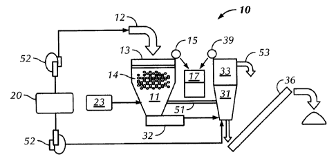
recovering bitumen oil. Referring initially to Figures 1 and la together, a
system 10
for removing bitumen oil from oil sand 12 in accordance with an embodiment is
shown. System 10 includes a primary separation tank 11 where oil sand 12 and
solid
matter (containing bitumen oil and cuttings) may be introduced. In one
embodiment,
oil sand 12 may be introduced into system 10 through an inlet 13 configured to
mix
oil sand 12 with water, thereby creating a first slurry 14. First slurry 14
may then
separate in primary separation tank 11.
100281 In one embodiment, the initial separation of first slurry 14 may take
place
through gravity separation. To provide gravity separation, primary separation
tank
11 may be any holding vessel known to one skilled in the art used in the
process of
oil/water separation. Gravity separation devices work on the principle of
Stokes'
Law:
Vs = gd2(PP-pm)/18g
7
CA 02580098 2010-06-23
wherein VS = settling rate, g = acceleration of gravity, P, = density of
particle,
Pm = density of medium, and = viscosity of medium. Stokes' Law defines the
rise
velocity of an oil particle based on its density and size. Lighter particles,
like
bitumen oil (i.e. those having a relatively low specific gravity) tend to
float to the
surface, while heavier particles, like sand (i.e. those having a relatively
high specific
gravity) tend to settle to the bottom of primary separation tank 11. Because
the
specific gravities of bitumen oil and water tend to be closer than the
specific gravities
of bitumen oil and particulate contaminated water, the contaminated water
tends to
settle to the bottom of primary separation tank 11, along with the sand.
[00291 Still referring to Figure 1, as the bitumen oil rises to the top of
primary
separation tank 11, a first hydrocarbon removing device 15 may be used to
remove
the bitumen oil from the surface of the water. In one embodiment, first
hydrocarbon
removing device 15 may be a disc skimmer. As the disc skimmer removes bitumen
oil from the surface of first slurry 14, the bitumen oil may be transferred
into a
product collection tank through a conveying line (not shown in detail), an
overflow,
or any other process known to one of ordinary skill in the art.
100301 To facilitate the initial separation of bitumen oil from oil sand 12, a
stream of
hot water may be added to oil sand 12 at inlet 13. In one embodiment, hot
water may
be supplied from a water heater 20 and transferred to inlet 13 through a water
pump
15, or any other process known to one of ordinary skill in the art. In certain
embodiments, heating the water to about 90 C may increase the rate that
bitumen oil
separates from oil sand 12, clay, or other solids. Pumps 52 are also shown.
[00311 While gravity separation may encourage bitumen oil to separate from
solids,
agitation of first slurry 14, in primary separation tank 11, may assist in the
process.
In one embodiment, the agitation of first slurry 14 may occur through aeration
supplied to primary separation tank 11 from an air compressor 23. The air may
be
added to first slurry 14 through holes drilled in the bottom of primary
separation tank
8
CA 02580098 2007-03-01
11. As the air rises through first slurry 14, the air may promote the
separation of
bitumen oil from solids by trapping the bitumen oil on the surface of bubbles.
The
bubbles may then rise to the surface of first slurry 14 in the form of a
froth. The froth
may be removed from primary separation tank 11 by first hydrocarbon removing
device 15, and transferred to product collection tank 17. In certain
embodiments, it
may be beneficial to use hot water separation, air agitation, and other
processes of
separation known to one of ordinary skill in the art, in the same system, to
increase
the rate of bitumen oil separation.
[0032] Still referring to Figure 1, while bitumen oil may separate from first
slurry 14,
and layer on the top of primary separation tank 11, solids may settle toward
the
bottom of primary separation tank 11. Between the layer of primarily solids,
and the
layer of primarily bitumen oil, a middle layer of first slurry 14 may form.
The
middle layer may contain fine particles, bitumen oil, and water. Because the
middle
layer may contain bitumen oil, it may be beneficial to transfer the middle
portion of
first slurry 14 to a secondary separation tank 33. The middle layer of first
slurry 14
may be transferred to secondary separation tank 33 via direct piping 51,
siphoning,
through a pumping device (not shown in detail), or by any other process known
to
one of ordinary skill in the art.
[0033] While the middle layer of first slurry 14 may be transferred to
separation tank
33 as described above, the solids that may have settled to the bottom of
primary
separation tank 11 may also be transferred. To transfer solids from primary
separation tank 11 to secondary separation tank 33, a solid transfer device 32
may be
used. In one embodiment, solid transfer device 32 may be a variable pitch
screw
auger (not shown in detail). As solids settle to the bottom of primary
separation tank
11, the solids of first slurry 14 may enter the auger. The auger may transfer
the
solids directly into secondary separation tank 11, or may provide additional
components to facilitate the separation of bitumen oil from the solids. For
example,
9
CA 02580098 2007-03-01
in certain embodiments, a stream of hot water may be introduced into the auger
to
promote the separation of remaining bitumen oil from the solids. While hot
water
separation is one method of bitumen oil separation that may be used in solids
transfer
device 32, embodiments employing other processes of separation may be
foreseen,
and are within the scope of this disclosure.
100341 Still referring to Figure 1, a second slurry may form in secondary
separation
tank 33 including the middle layer of first slurry 14, and the solids from
solid transfer
device 32. Second slurry 31 may initially separate through gravity separation,
as
described above. However, in certain embodiments, it may be advantageous to
use
any of the agitation processes used in primary separation tank 11 to increase
the rate
bitumen oil separates from the solids. In one embodiment, hot water may be
introduced into secondary separation tank 33. The hot water may be supplied to
secondary separation tank 33 by a water pump 51 connected to water heater 20.
In
such an embodiment, it may be beneficial to introduce the hot water into the
bottom
of secondary separation tank 33 so that the hot water has greater contact with
the
solids. As the hot water contacts the solids, additional bitumen oil may
separate from
the solids and rise to the top of secondary separation tank 33 as described
above.
100351 Alternatively, agitation of second slurry 31 may be induced through the
injection of air into secondary separation tank 33. In one embodiment, air may
be
injected into the bottom of secondary separation tank 33 from air compressor
23.
Aeration may promote the separation of bitumen oil from solids, as described
above.
It should be realized that in certain embodiments, any of the aforementioned
methods
of agitating the first slurry may be used together, no method of agitation may
be used
at all, or other methods known to those of ordinary skill in the art may be
used.
[0036) As the bitumen oil is released from the solids, it may rise to the top
of
secondary separation tank 33. The oil may then be removed from secondary
separation tank 33 by a second hydrocarbon removing device 39. In one
CA 02580098 2007-03-01
embodiment, second removing device 39 may be a disc skimmer (not shown in
detail). As the disc skimmer removes bitumen oil from the surface of second
slurry
31, the bitumen oil may be transferred to product collection tank 17 as
described
above.
[00371 To remove the solids from secondary separation tank 33, a fine particle
separation device 36 may be configured to secondary separation tank 33. In one
embodiment, fine particle separation device 36 may be an auger (not shown in
detail). In such an embodiment, as solids settle toward the bottom of
secondary
separation tank 33, the solids may enter the auger. As the solids travel
through the
auger toward an exit location, liquid may drain off of the solids and back
into
secondary separation tank 33. Upon exiting the auger, the cleaned solids may
exit
the system, or in certain embodiments, enter another separation tank for
additional
cleaning.
100381 Referring back to Figure 1, as the bitumen oil rises to the top of
secondary
separation tank 33, and the solids settle to the bottom of secondary
separation tank
33, a middle layer in second slurry 31 may form. The middle layer in second
slurry
31 may contain water and clay. In some embodiments, the middle layer in second
slurry 31 may be removed from secondary separation tank 33, to a dewatering
unit
(not shown), via direct piping 53, siphoning, through a pumping device (not
shown),
or by any other process known to one of ordinary skill in the art. The
dewatering unit
may promote the separation of clay from water, such that the cleaned water may
be
recycled. In certain embodiments, the cleaned water may be recycled into
system 10
through water heater 20, forming a closed-loop water cycle.
100391 Referring now to Figure lb, an alternate embodiment of a system 110 for
removing bitumen oil from oil sand is shown. The system 110 includes a primary
separation tank 111 where oil sand 112 and solid matter (containing bitumen
oil and
cuttings) may be introduced. In one embodiment, oil sand 112 may be introduced
11
CA 02580098 2007-03-01
into system 110 through a first inlet 113 configured to mix the oil sand 112
with
water, thereby creating a first slurry 114. First slurry 114 may then separate
in
primary separation tank 111 as described above.
[00401 Still referring to Figure lb, as the bitumen oil rises to the top of
primary
separation tank 111, a first hydrocarbon removing device 115 may be used to
remove
the bitumen oil from the surface of the water. In one embodiment, first
hydrocarbon
removing device 115 may be a rotary skimmer. As the rotary skimmer collects
the
bitumen oil, the oil may be transferred to an overflow 116 attached to primary
separation tank 111. The bitumen oil may then be transferred to a product
collection
tank 117 via a conveying line 118 through positive displacement provided by
pump
119. While this is one method of transferring the bitumen oil, it should be
recognized that any method of transferring the separated bitumen oil from
primary
separation tank 111 to product collection tank 117 is within the scope of this
disclosure.
[00411 While gravity separation may facilitate in the initial separation of
bitumen oil
from solids, the initial separation of first slurry 114 may be further
assisted by its
agitation in primary separation tank 111. As shown in Figure lb, a boiler 120
may be
attached to primary separation tank 111 to introduce steam 121 into first
slurry 114.
As steam 121 interacts with first slurry 114, the bitumen oil may separate
from oil
sand 112 and the water to form a froth on the surface of first slurry 114. The
froth
may then be removed from the surface of first slurry 114 and transferred to
product
collection tank 117 in the method described above.
100421 Alternatively, agitation to first slurry 114 may be provided through a
stream of
air 122 introduced into the first slurry 114 through an air compression device
123
attached to primary separation tank 111. In one embodiment, air 122 may be
introduced in the form of microbubbles that travel through first slurry 114
inducing
separation of the bitumen oil from oil sand 112 and the water. As the bitumen
oil
12
CA 02580098 2007-03-01
separates from the oil sand 112 and water, it floats to the surface of primary
separation tank 111 in the form of a froth that may be removed from primary
separation tank 111 through any method described above.
100431 Alternatively still, agitation to first slurry 114 may be provided by a
stirring
device 124. As depicted in Figure lb, stirring device 124 may be a shaft 125
actuated by a motor 126. To provide movement in first slurry 114, one or more
propellers 127 may be attached along shaft 125. To promote separation of the
bitumen oil from first slurry 114, propellers 127 may be configured to provide
specific flow dynamics (e.g. directional or counter-current flow). It should
be
realized that in certain embodiments, any of the aforementioned methods of
agitating
the first slurry may be used together, no method of agitation may be used at
all, or
other methods known to those of ordinary skill in the art may be used.
[0044] Referring briefly to Figure 2, in one embodiment, primary separation
tank
111 may be an American Petroleum Institute (API) separator 210. Oil sand, mud,
and cuttings may be mixed with water and introduced into API separator 210
through
a first inlet 213 creating a counter-current flow. A cross flow 214 may be
produced
using a circulation pump (128 of Figure Ib). Cross flow 214 of water creates a
positive flow direction 215 whereby bitumen oil flows toward effluent end 212
and
sand moves toward inlet end 211. While this is one method of creating a
counter-
current in primary separation tank 111, other methods may be foreseen wherein
bitumen oil is collected by any means known to one of ordinary skill in the
art. For
example, in certain embodiments, it may be beneficial to use coalescing plate
or
inclined plate separators to increase the rate of bitumen oil extraction from
oil sand
112.
[0045] Additionally, a modification to primary separation tank 111 wherein a
chain-
and-flight scraper may be used to facilitate the movement of sand away from
the
bitumen oil may be foreseen. API separator 210 may be configured with a chain-
13
CA 02580098 2007-03-01
and-flight scraper to move oil sand 112 and solids throughout the vessel.
Generally,
a system using a chain-and-flight scraper will move solids to an inlet end 211
of API
separator 210 while floating bitumen oils to an effluent end 212 of the of the
separator. A system employing a chain-and-flight scraper (not shown
separately)
may be of specific advantage when processing large quantities of sand in a
single
run.
[00461 Alternative modifications to primary separation tank 111 may also
include a
movable first water inlet that allows solids to be injected into primary
separation tank
111 at selectable points along the tank. By varying the entry location of the
solids,
the height of the solids in primary separation tank 111 may be kept relatively
level
thereby promoting the extraction of bitumen oil. In addition to a movable
first water
inlet, a second water inlet may be foreseen wherein a horizontal flow of water
flows
through the tank substantially continuously washing the solids. These
modifications
may be used independently, in conjunction with aforementioned aspects of
primary
tank design, or not at all, depending on the requirements of the solids being
processed.
[00471 Referring back to Figure lb, primary separation tank 111 may be fluidly
connected to a solid transfer device 132. In certain embodiments, solids
transfer
device 132 may include an eductor system 129. Via a fluid connection, the
eductor
system 129 receives the solids which have settled to the bottom of primary
separation
.tank 111. In the eductor system 129, water may be provided through second
water
inlet 130 in order to mix with the solids, thereby creating a second slurry
131.
Second slurry 131 may be transferred to a solid separation device 132
connected to
the eductor system 129. One solid separation device that may be used is a
hydrocyclone. In a hydrocyclone system, second slurry 131 may be fed
tangentially
into the larger diameter portion of the cone. The spinning effect of the
hydrocyclone
forces solids to the edge of the cone where they slide down the sides of the
device
14
CA 02580098 2007-03-01
exiting from the bottom. The solids, consisting of cleaned sand and cuttings
may
then be collected. The liquid portion of second slurry 131, generally
including the
water and bitumen oil, exits the top of the hydrocyclone and enters a
secondary
separation tank 133.
[00481 In one embodiment, the eductor system 129 may include a variable pitch
screw auger (not shown). In certain embodiments, the variable pitch screw
auger
may be placed with an inlet at the bottom of primary separation tank 111. As
the
screw auger contacts the solids, the solids may be drawn out of primary
separation
tank 111 along a screw conveyer. As the solids are transferred out of primary
separation tank 111 along the screw conveyer, water may drain back into
primary
separation tank 111 for further processing. During or after transference
through the
variable pitch screw auger, the solids may be washed with water, treated with
additives, or otherwise deposited in a solid separation device 142 or
secondary
separation tank 133. While only a variable pitch screw auger is described
above, it
should be understood that any transference device known to one skilled in the
art
may be used to move solids from primary separation tank 111 to secondary
separation tank 133.
100491 In one embodiment, upon exiting the eductor system 129 or solid
separation
device 142, the solids may pass through a shale shaker 134. Shale shaker 134
accepts the solids from solid separation device 132, and is configured to
attach to
secondary separation tank 133. Generally, the shale shaker 134 is a vibrating
sieve,
wherein as solids and residual second slurry 131 move over a cloth or mesh
screen,
liquids and solids smaller than the mesh pass through the screen into the
secondary
separation tank. Larger particles, including cuttings, retained on the screen,
travel to
the end of shale shaker 134, and are collected therefrom. The portion of
second
slurry 131 that passes through shale shaker 134 mixes with a solution in
second
separation tank 133.
CA 02580098 2007-03-01
[00501 Upon entering the second separation tank 133, gravity separation may
allow
remaining bitumen oils to layer toward the surface, while the particulate
matter layers
toward the bottom. The particulate matter that layers toward the bottom of
secondary
separation tank 133 may then enter a fine particle separation device 136. The
fine
particle separation device 136 may be external to secondary separation tank
133 or
inside secondary separation tank 133.
(00511 In one embodiment, the particulate matter may flow out of the secondary
separation tank 133 into fine particle separation device 136 via an outlet
located at a
height level on secondary separation tank 133 where the particulate matter
layers.
However, in other embodiments, the particulate matter may be removed from
secondary separation tank 133 with either an internal or external water pump.
In
one embodiment, fine particle separation device 136 may be a centrifuge.
Generally,
the centrifuge consists of a rotating conical drum actuated by an external
motor. A
mixture of fine particulate matter (e.g. sand, fine cuttings, middlings) and
water
enters one end of the centrifuge. As the drum rotates, separated solids exit
from one
end for collection, while the mixture of water and remaining bitumen oil exits
the
second end and are thereby transferred to a partitioned section 133a of
secondary
separation tank 133. In some embodiments, use of a transfer pump 137 may be
foreseen to facilitate movement of the water and bitumen oil into the
partitioned
section of secondary separation tank 133a.
100521 In certain embodiments, fine particle separation device 136 may be a
discharge auger (not shown in detail). The discharge auger may be placed with
an
inlet in secondary separation tank 133. As solids layer toward the bottom of
secondary separation tank 133, the discharge auger removes the solids, while
draining any liquids back into secondary separation tank 133. The discharge
auger
may be a solid state discharge auger, a screw auger, or any other auger style
conveying device known to one of ordinary skill in the art.
16
CA 02580098 2007-03-01
[0053] Referring to Figure lb, the partitioned section of secondary separation
tank
133a may allow bitumen oil to separate from the water. As bitumen oil layers
to the
top of the partitioned section of secondary separation tank 133a, the bitumen
oil may
be transferred into a final separation tank 135 by, for example, an overflow
138.
Final separation tank 135 may allow the bitumen oil to separate from the water
by
gravity separation. However, in some embodiments, agitation from steam, air,
or
physical movement, as described above, may be used to stimulate the separation
of
the bitumen oil. As layers form in the water, a second hydrocarbon removing
device
139 may be used to remove the bitumen oil whether layered, or as a froth.
[0054] In one embodiment, second hydrocarbon removing device 139 may be a drum
skimmer (i.e. an oil roll skimmer). Generally, a drum skimmer contains an
external
drive that rotates a drum. As the drum rotates over the surface of the water,
bitumen
oil adheres to the surface of the drum, and a blade removes the accumulated
oil from
the surface of the skimmer. The bitumen oil then flows through a collection
trough
and into product collection tank 117. Use of a drum skimmer may be
advantageous
because it will not remove floating debris, thereby maintaining the purity of
the
collected bitumen oil.
[0055] While the embodiment of system 110 described above includes a secondary
separation tank 133 and a final separation tank 135, it should be realized
that in
certain embodiments, the described components of final separation tank 135 may
be
included in secondary separation tank 133. In such an embodiment, final
separation
tank 135 may remain in system 110 as a water repository, or may be removed
from
system 110 entirely. Embodiments may also be foreseen, wherein fine particle
separation device 136, second hydrocarbon removing device 139, and the water
outlet to primary separation tank 111 are included in different tanks. In such
a
system, all of the secondary separation tanks 133 may remain operatively
connected,
while serving different functions. In still another embodiment, a system 110
may be
17
CA 02580098 2007-03-01
foreseen, wherein there are any number of tanks including multiple stages of
fine
particle separation, skimming, and water transference.
[00561 In certain embodiments, surfactants, wetting agents, causticizing
agents, and
other chemical cleaning substances may be used either by direct addition to
the
described processes or as additives to the mechanical and hydraulic processes
used to
remove the tar sand from the mined or drilled deposits. Further, specified
ranges of
temperature and pH may be used to facilitate bitumen oil extraction.
Specifically, in
embodiments wherein the temperature of the solids as they enter the system is
at
either ambient temperature or the temperature of the fluid returning from the
well, the
process temperature may be above 50 C, preferably above 75, and the water
feed
temperature is about 90 C may increase the efficiency of bitumen oil
extraction.
Steam heat may also be used in systems including a boiler. While these
temperature
ranges may promote efficient bitumen oil extraction, the use of temperatures
outside
this range may be foreseen, and as such, are within this disclosure.
Additionally, a
system wherein the process maintains alkaline pH, of about 10, and preferably
above
11, may also facilitate bitumen extraction.
[00571 Referring to Figure 3, a block diagram of the process flow of one
embodiment
is shown. Oil sand and water enter primary separation tank 311 wherein bitumen
oil
is collected and transferred to a product collection tank 317. The remaining
solids
exit primary separation tank 311 and enter an eductor system 329. The eductor
system 329 mixes the solids with water and transfers the slurry to a solid
separation
device 342. Solid separation device 342 removes large and medium size cuttings
for
collection. The remaining slurry may be transferred to a secondary separation
tank
333. Secondary separation tank 333 uses a fine particle separation device
(e.g. 136
of Figure lb) to remove fine particulate matter from the solution. The fine
particulate matter is separated out for collection, and the remaining solution
of water
and bitumen oil is transferred to a final separation tank 335. Final
separation tank
18
CA 02580098 2007-03-01
335 may use a second hydrocarbon removing device (e.g. 139 of Figure lb) to
remove the bitumen oil to product collection tank 317.
100581 Referring to Figure lb and Figure 4 together, a water flow block
diagram of
a closed loop water cycle 410 of an embodiment of Figure lb is shown. Oil
sand,
cuttings, and other solid matter may enter system 110 through first water
inlet 130 of
primary separation tank 111. Water from an outlet on secondary separation tank
133
may also flow into first water inlet 130 of primary separation tank 111,
therein
mixing with the solids as they are added to system 110. Water transfer between
secondary separation tank 111 and primary separation tank 111 may be assisted
by an
external water pump 140, or any other means of inducing water transfer known
to
one skilled in the art, for example, through an in tank water pump or by
siphoning.
100591 Water may then flow from primary separation tank 111 into eductor
system
129. The eductor system 129 may receive additional water from final separation
tank
135. In one embodiment, the water may exit through an outlet in final
separation
tank 135 and flow into a second water inlet 130 of eductor system 129. The
water
transfer may be assisted by external water pump 140, a separate water pump, or
any
other means of inducing water transfer know to one skilled in the art. In
eductor
system 129, the water from final separation tank 135 mixes with the solids and
fluids
from primary separation tank 111.
100601 The water from eductor system 129 may then flow into solid separation
device
132 for processing. After processing, the water may then flow into secondary
separation tank 133 by overflow, piping, or any other means of transference.
In some
embodiments, the water may flow directly into secondary separation tank 133,
while
in other embodiments, the water may flow through a second solid separation
device,
for example a shake shaker 134.
[00611 The water may then flow from secondary separation tank 133 into fine
particle
separation device 136. After processing in fine particle separation device
136, the
19
CA 02580098 2007-03-01
water may then flow back into secondary separation tank 133 or any partition
of
secondary separation tank thereof. The cycle of water from secondary
separation
tank 133 to fine particle separation device 136 may be induced by transfer
pump 137,
or any other water flow device known to one skilled in the art. Some of the
water
may exit secondary separation tank 133 through an outlet configured to connect
with
primary separation tank 111 as described above.
[0062] Upon processing by fine particle separation device 136, water not
directed to
primary separation tank 111 may flow from secondary separation tank 133 (or
any
partition thereof) into final separation tank 135. The water flow from
secondary
separation tank 133 to final separation tank 135 may occur through overflow
138 or
mechanical means.
[0063] The solution in final separation tank 135 will consist primarily of
water and
bitumen oil. As the bitumen oil is removed to product collection tank 117, the
water
may be transferred to eductor system 129 as described above. To prevent the
reprocessing of bitumen oil or residual solid matter, a filter 141 may be
attached to
the outlet connecting final separation tank 135 to eductor system 129.
[0064] The closed loop water cycle 410 disclosed above may allow water to be
recycled through system 110 with increased efficiency. Advantageously, closed
loop
water cycle 410 may recycle the initial water in system 110, thus reducing
operating
costs. Additionally, by recycling the water in a system using heated water,
less water
may have to be heated, driving down operating costs even further. Moreover,
closed
loop water cycle 410 may allow levels of pH (e.g. causticity) to be monitored
and
maintained with greater accuracy and ease. Because less external water may be
added to system 110, less caustic reagent may be required, thus decreasing
operating
costs while increasing system efficiency.
[0065] Referring to Figure 5, a block diagram of an alternate embodiment of a
system
510 for removing bitumen oil is shown. Oil sand and water enter a primary
CA 02580098 2007-03-01
separation tank 511 wherein bitumen oil is collected and transferred to a
product
collection tank 517. The remaining solids exit primary separation tank 511 and
enter
an eductor system 529. Eductor system 529 mixes the solids with water and
transfers
the slurry to a secondary separation tank 533. Secondary separation tank 533
may
use a final particle separation device (e.g. 136 of Figure 1) to remove fine
particulate
matter from the solution. The fine particulate matter may be separated out for
collection. Bitumen oil may then removed from secondary separation tank 533,
in
any one of the processes described above, and transferred to product
collection tank
517. Water from secondary separation tank may then be transferred to a
dewatering
tank 550. Remaining solid matter, including sand and clay, may then be removed
from the water. The water may then be heated and pumped back into the system.
100661 Referring to Figure 5 and Figure 6 together, a water flow block diagram
of a
closed loop water cycle 610 of an embodiment of Figure 5 is shown. Oil sand,
cuttings, and other solid matter may enter system 510 through a first water
inlet.
Water from an outlet on a dewatering tank 650 may also flow into a water inlet
of a
primary separation tank 611, therein mixing with the solids as they are added
to
system 610. Water transfer between dewatering tank 611 and primary separation
tank 611 may be assisted by an external water pump, or any other means of
inducing
water transfer, as described above.
[00671 Water may then flow from primary separation tank 611 into an eductor
system
629. Eductor system 629 also receives water from dewatering tank 650. In one
embodiment, the water may exit through an outlet in dewatering tank 650 and
flow
into a second water inlet of eductor system 629. The water transfer may be
assisted
by external water pump, a separate water pump, or any other means of inducing
water transfer know to one skilled in the art. In eductor system 629, the
water from
dewatering tank 650 mixes with the solids and fluids from primary separation
tank
611.
21
CA 02580098 2007-03-01
[0068] The water may then flow from a secondary separation tank 633 into a
fine
particle separation device. After processing in a fine particle separation
device, the
water may then flow back into secondary separation tank 633 or any partition
of
secondary separation tank thereof. The cycle of water from secondary
separation
tank 633 to the fine particle separation device may be induced by a transfer
pump, or
any other water flow device known to one skilled in the art.
[0069] Water from secondary separation tank 633 may then be transferred to
dewatering tank 650. In dewatering tank 650, the water may be heated by an
external
source prior to being transferred to either primary separation tank 611 or
eductor
system 629. This embodiment of closed loop water cycle 610 may provide the
same
advantages as discussed above.
[0070] Finally, referring to Figure 7, an auxiliary system 710 of an
embodiment is
shown. One example of auxiliary processing system 710 may include an air
compression device 723 and a boiler 720. In one embodiment, air may be
injected
into a primary separation tank 711 and final separation tank 735 through air
compression device 723. Upon injection into either primary separation tank
711, or
final separation tank 735, the air flow may be manipulated to induce the
formation of
microbubbles in the water, which may increase the separation rate of bitumen
oil
from solids. In certain embodiments, an air flow rate of 1500 L/min may
promote
efficient bitumen oil separation. However, other embodiments may be foreseen
wherein air is injected at different rates, or into different parts of a
system (e.g. 110
of Figure 1 b).
[0071] A second example of auxiliary system 710 may include a boiler 720.
Boiler
720 may receive water from a source either within the system, for example,
from
final separation tank (e.g. 135 of Figure lb), or an external source (not
shown). In
one embodiment, boiler 720 produces steam, and may inject the steam into
primary
separation tank 711 and final separation tank 735. The steam may be injected
into
22
CA 02580098 2007-03-01
primary separation tank 711 and final separation tank 735 at any level
throughout the
system which increases the separation rate of bitumen oil from solids.
100721 While air compression device 723 and boiler 720 may make up an
auxiliary
system individually, in certain embodiments, it may be advantageous to inject
both
air and steam into a system (e.g. 110 of Figure lb). It should also be
realized that
other auxiliary systems may be foreseen wherein chemicals are used to further
increase the efficiency of the separation of bitumen oil from solids.
100731 Advantageously, embodiments of the aforementioned system may promote
increased rates of separation of bitumen oil from solids. Because the system
may use
a closed loop water cycle, less water may be used, increasing efficiency, and
decreasing costs. These cost saving may be further realized when the system
uses a
hot water process, chemical additives, or other means of increasing separation
time.
While decreasing costs associated with bitumen oil separation, the system may
also
decrease the production of hazardous waste material. Because of the closed
cycle
nature of the system, fewer resources are required to operate and maintain the
processes. Furthermore, because the solid matter may be cleaned in multiple
steps,
sand and cuttings used to backfill petroleum extraction operations may contain
less
residual petroleum products and chemicals, thus being safer for the
environment.
Finally, the removed bitumen oil may contain less water by weight, decreasing
the
need for subsequent refinement operations, thereby increasing the speed of
production while decreasing costs.
[00741 While the invention has been described with respect to a limited number
of
embodiments, those skilled in the art, having benefit of this disclosure, will
appreciate that other embodiments can be devised which do not depart form the
scope of the invention as disclosed herein. Accordingly, the scope of the
invention
should be limited only by the attached claims.
23