Note: Descriptions are shown in the official language in which they were submitted.
i
CA 02580153 2014-06-17
. .
INTEGRATED PARTICULATE FILTRATION AND
DEWATERING SYSTEM
TECHNICAL FIELD
Disclosed embodiments herein relate generally to filtering systems, and more
particularly to an integrated filtration and dewatering system and related
methods for
filtering particulate matter from a contaminated fluid.
BACKGROUND
One of the more common technologies for treating waste water is based on a
settling
process, often using fixating agents such as hydroxide and sulfates. The
fixating chemicals
are added to water in a settling tank to absorb or otherwise transform the
contaminants into
materials which settle to the bottom of the tank. This technology uses
comparatively simple
equipment and permits the processing of large volumes of waste waters, without
adding
materials which would result in an environmentally undesirable effluent
stream. In fact, in
some systems, no fixing agents are used because the contaminants are
sufficiently large to
settle in the tanks. However, in many cases, use of ordinary settling
processes fails to
reduce contaminant concentrations to levels low enough to meet desired
requirements,
without using excessive amounts of materials, over a protracted processing
time. In
addition, traditional settling processes often require extremely large
settling reservoir to
provide adequate settling time for smaller particles.
In addition to settling tanks, conventional treatment processes to remove
undissolved
solids include the use of settling tanks, clarifiers, centrifuges, gravity
filters and pressure
1
i
CA 02580153 2014-06-17
, .
filters. The processed effluent, freed of undissolved solids by such
techniques or combined
techniques still requires further processing to remove dissolved solids.
Conventional
approaches to removing dissolved solids include precipitation initiated by pH
adjustment or
reagent addition, flocculation and settling, micro-filtration and precipitate
concentration
through centrifuge or plate press action.
The composition of filter elements for such techniques, depending on the
process
employed and particulate matter to be removed, can be perforated or slotted
metal, or
polymeric elements such as polypropylene or polyester cartridges. High density
inorganic
adsorbent materials (HDIA) can also be used to promote solid separation in the
flocculation
phase. Typically, these materials have been natural or synthetic low density
aluminum
silicates called zeolites, used to capture positively charged ions of the
filtered elements. In
addition, beds of sand or other particulate matter are used in a mechanical
filtration process
called polishing. The contaminated water is passed one or more times through
the bed with
or without periodic backwashes to flush the entrapped residue upstream for
flocculation and
micro-filtration.
These known procedures and techniques for separating and removing aqueous
based
contaminants greatly reduce the environmental hazards. Unfortunately, however,
a high
degree of desired effluent purity may require repeated cycling through the
individual
filtration steps with associated storage, time, and cost penalties, if such a
high level can be
achieved at all. As a result, available conventional systems can suffer one or
more of the
short-comings discussed above.
2
CA 02580153 2014-06-17
BRIEF SUMMARY
The disclosed principles provide for a chemical-free filtering of particulate
down
below sub-micron levels, while concentrating the particulate into a sludge.
The disclosed
principles integrate cross-flow filtration (i.e., micro-filtration or ultra-
filtration) with a
settling tank (or "weir") to provide sequential filtration and dewatering of
an aqueous media.
The disclosed technique operates chemical-free and is continuous in a closed-
loop system.
Applications for systems and processes in accordance with the disclosed
technique are wide,
and include aggregate fines removal, sediment removal, replacement for
clarifiers, etc.
In one aspect, an integrated filtration and dewatering system for filtering
particulate
matter from a contaminated fluid is provided. In one embodiment, the system
comprises a
feed stream providing a contaminated fluid into the system. In addition, such
a system
includes at least one settling tank for holding the contaminated fluid so that
at least some of
the particulate matter settles to the bottom of the at least one settling
tank. This embodiment
of a system also includes a cross-flow filter for filtering fluid taken from
near the top of the
volume of fluid in the at least one settling tank for removing substantially
all remaining
particulate matter from the fluid, as well as an output stream disbursing
filtered fluid from
the cross-flow filter outside the system.
In another aspect, a method of filtering and dewatering particulate matter
from a
contaminated fluid is provided. In one embodiment, a method comprises
providing a
contaminated fluid via a feed stream, and holding the contaminated fluid in at
least one
settling tank to cause at least some of the particulate matter to settle to
the bottom of the at
least one settling tank. In addition, the method could include filtering fluid
taken from near
the top of the volume of fluid in the at least one settling tank with a cross-
flow filter to
3
1
CA 02580153 2014-06-17
. .
remove substantially all remaining particulate matter from the fluid. Then,
such a method
could include disbursing filtered fluid from the cross-flow filter.
BRIEF DESCRIPTION OF THE DRAWINGS
For a more complete understanding of this disclosure, and the advantages of
the
systems and methods herein, reference is now made to the following
descriptions taken in
conjunction with the accompanying drawings, in which:
FIGURE 1 illustrates a high-level block diagram demonstrating integrated
filtration
and dewatering according to the disclosed principles;
FIGURE 2 illustrates one embodiment of an integrated filtration and dewatering
system constructed according to the disclosed principles;
FIGURE 3 illustrates another embodiment of an integrated filtration and
dewatering
system constructed according to the disclosed principles; and
FIGURE 4 illustrates yet another embodiment of an integrated filtration and
dewatering system constructed according to the disclosed principles.
DETAILED DESCRIPTION
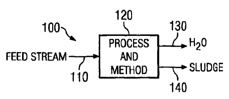
Referring initially to FIGURE 1, illustrated is a high-level block diagram 100
demonstrating integrated filtration and dewatering according to the disclosed
principles.
The diagram 100 includes a feed stream 110, which provides an incoming aqueous
media in
need of filtration. The feed stream enters the disclosed process and method
120, which is
discussed in greater detail below, such that the non-aqueous particles in the
media are
filtered from the feed stream 110.
4
,
CA 02580153 2014-06-17
Once filtered and dewatered in accordance with the disclosed principles, the
media in
the feed stream 110 is separated into two distinct outputs. Specifically, the
contaminated
aqueous media is separated by the disclosed process into water 130 (in this
example) and a
sludge 140 comprising the particles filtered (and "dewatered") by the
disclosed process 120.
__ While a contaminated aqueous media is discussed throughout the present
disclosure, it
should be noted that any type of liquid in need of particle filtration may
been filtered in
accordance with the disclosed principles, as will be clear from the discussion
below.
Turning to FIGURE 2, illustrated is one embodiment of an integrated filtration
and
dewatering system 200 constructed according to the disclosed principles.
Stated another
__ way, the disclosed principles provide for a dewatering and reuse system
(DeWRSTM) for
removing particulate matter from fluids. The system 200 includes a feed line
210 where a
liquid media in need of having particles therein filtered out is fed into the
system 200. For
example, the contaminated media may contain particulate matter, such as
aggregate fines
that may accumulate in a liquid used as a coolant.
More specifically, in construction applications involving the wet-cutting of
concrete,
tile or certain stones, water is typically employed as a coolant (and for dust
suppression) for
the blade. As the water (or other coolant liquid) is sprayed onto the blade or
other parts of
the saw during cutting, aggregate fines build-up in the coolant run-off. When
the coolant is
sought to be recycled during the cutting operation, the build-up from the
particulate matter
__ coming off of the concrete, tile or stone should be filtered from the
coolant so as not to clog
or otherwise detrimentally impact the coolant circulation system. Thus, the
system 200 in
FIGURE 2 may be employed to efficiently filter the particulate from the
contaminated liquid
coolant so that the filtered coolant may be recirculated without problems. Of
course, while
5
CA 02580153 2014-06-17
the below discussion refers to aggregate fines in such an exemplary wet-
cutting application,
those skilled in the art will see the broader application of the disclosed
systems and
processes.
Looking specifically at this type of application, the used liquid media is
input to the
system 200 via the feed line 210 and pumped, via a sump pump 220, into one or
more
settling tanks 230a, 230b through an intake line 240. In some embodiments, the
first settling
tank 230a may specifically be a decanting tank, removing a larger
concentration of
particulate matter early in the process. Of course, the second tank 230b may
also be
considered a decanting tank. In addition, the system 200 may include a sieve
250 prior to
the settling tanks 230a, 230b for filtering and breaking down larger aggregate
fines in the
incoming media. While the sieve 250 is not required, it may prove beneficial
to employ it so
as to prevent clogging of the system 200 with oversized particles further down
the line.
Once the media reaches the settling tanks 230a, 230b, gravity is used to begin
the
filtering process. Specifically, within the settling tanks 230a, 230b, there
is a particulate
concentration gradient where the highest concentration is at the bottom, and
the lowest is at
the top. As mentioned, gravity is used to create the solids/particulate
concentration gradient
as the heavier particulate matter drops to the bottom of the tanks 230a, 230b.
While two
settling tanks 230a, 230b are illustrated in this embodiment, the disclosed
principles are
broad enough to encompass one tank, two tanks, or even three or more settling
tanks,
depending on the particular application. Of course, the greater the number and
size of tanks,
the longer the settling time of the incoming fluid.
While gravity causes the particulate matter to drop to the bottom of the tanks
230a,
230b, fluid is pumped from near the top of the tanks 230a, 230b and is fed to
a cross-flow
6
CA 02580153 2014-06-17
filter 270. The fluid is pumped into the cross-flow filter 270 via line 260
and using, in this
embodiment, a circulation pump 270a. The cross-flow filter 270 separates and
concentrates
the solids/particulates, and the concentrated fluid is sent back to the
settling tanks 230a,
230b via return line 270b. The concentrated fluid is discharged near the
middle of the tanks
230a, 230b to allow the solids to drop and the water to rise, and as such
helps to maintain the
solid/concentration gradient. The permeate from the cross-flow filter 270
(essentially free of
solids) is output from the filter 270 via output line 270c. The permeate may
be output to a
storage tank 280 where it can then be re-used or discharged. For overall
efficiency, the
permeate flow rate and the raw feed (system intake) flow rate are balanced to
keep a
relatively constant level in the settling tanks 230a, 230b.
The construction of the cross-flow filter 270 may be selected based on the
intended
application for the system 200. For example, the filter element(s) may be
polymeric or even
ceramic. While polymeric filter elements are typically satisfactory for many
applications,
the type of particulate being filtered from the incoming fluid may result in
ceramic filter
elements being a better choice. This is especially the case when filtering
abrasive particulate
matter from the fluid. Aggregate fines, for instance, are relatively abrasive,
and would
likely tear apart a polymeric filter over time. As such, ceramic elements may
be the
preferred choice for most aggregate fines applications.
Aside from tolerating the abrasiveness of certain particulates, ceramic filter
elements
also have other advantages over polymeric or other similar element
compositions. For
example, the abrasiveness of those certain particulates act as a honing
material, which keeps
the ceramic filter element clean by the mere flow through the filter 270, and
eliminates the
need for potential chemical or mechanical cleaning maintenance requirements.
Thus,
7
CA 02580153 2014-06-17
ceramic elements used for abrasive particulates provides a method of 'self-
cleaning' the
filter 270. In addition, the filtered solid or particulate can create a
'dynamic filter' in the
ceramic element which provides smaller pore-size filtration capabilities as
the particulate
builds-up on the elements. This can prevent foulants from entering the
ceramic, and is
described in greater detail in U.S. Patent 6,136,203 and U.S. Application
Serial No.
11/044,377, which are commonly assigned with the present disclosure.
Regardless of the type of filter 270 element employed, at certain points
during
operation of the system 200, the filter 270 will eventually need to be cleaned
so that it's
efficiency is kept up. While polymeric filter elements are typically replaced,
ceramic
elements can be "back-pulsed" instead of back-washed. Thus these types of
elements are
typically useable in a continuous manner and even eliminates the loss of
permeate that is
typically used for back-washing other types of filters. Such sonic pulsing or
shock wave, or
"back-pulsing," of ceramic filter elements is disclosed in U.S. Patent
5,462,674, which is
also commonly assigned with the present disclosure. Further, ceramics are
intolerant to
degradation from chemicals (organic and inorganic), such as solvents, acids or
bases.
Ceramics also do not tear or rip, and the pore sizes do not stretch with time;
thus, ceramic
filters do not typically have to be replaced. Also, if the ceramic filters get
plugged with oil
(or other non-aqueous phase fluid), they can be re-stored by `burning'(i.e.,
"high
temperature degas") the filter element.
While a system constructed and operated according to the disclosed principles
can
operate almost continuously, eventually the particulate (or, more generally,
the sludge) in
the settling tanks 230a, 230b builds up over time. When this occurs, the build
up may be
removed from the tanks 230a, 230b in various ways. For example, the sludge may
be
8
CA 02580153 2014-06-17
scooped out, such as using a backhoe or other similar equipment. Optionally,
the tanks
230a, 230b may be drained and the sludge pushed or scraped out of the tanks
230a, 230b.
Once removed, if the particulate product is of value, then it may be stored
for use at a future
time. In such an application, the particulate may be Ti02, such as that found
in a
photocatalytic contamination treatment system. Over time, the TiO2 particulate
settled at the
bottom of the tanks 230a, 230b may be recovered and reused, further increasing
efficiency
and decreasing overall costs.
Looking now at FIGURE 3, illustrated is another embodiment of an integrated
filtration and dewatering system 300 constructed according to the disclosed
principles. This
system 300 still includes a feed line 310 where a liquid media in need of
having particles
therein filtered out is fed into the system 300. The contaminated media may
once again
contain basically any type of particulate matter, such as aggregate fines.
The system 300 also includes a sump pump 320 used to pump the media through
the
feed line 310 and into two settling tanks 330a, 330b through an intake line
340. In addition,
the system 300 may also include a sieve 350 prior to the settling tanks 330a,
330b for once
again filtering and breaking down larger particles in the incoming fluid, if
needed. Gravity
is used in the settling tanks 330a, 330b to provide the particulate
concentration gradient
discussed above, where the highest concentration is at the bottom and the
lowest is at the
top. Fluid is again pumped from near the top of the tanks 330a, 330b and is
fed to a cross-
flow filter 370. The fluid is pumped into the cross-flow filter 370 via line
360 and using,
once again, a circulation pump 370a. The cross-flow filter 370 is again used
to separate and
concentrate the solids/particulates, and the concentrated fluid is sent back
to the settling
tanks 330a, 330b via return line 370b. The permeate from the cross-flow filter
370 is output
9
CA 02580153 2014-06-17
from the filter 370 via output line 370c, and deposited in a storage tank 380
where it can
then be re-used or discharged.
The system 300 in FIGURE 3 differs from the system 200 in FIGURE 2 in that it
further includes an acidic reservoir 390. The acidic reservoir 390 may be
employed for
aggregate fines applications, as discussed above. Specifically, instead of the
filter
"cleaning" provided by the continuous flow of abrasive particulate discussed
above, when
the system 300 is idle for a given period of time, aggregate (e.g., calcium
carbonate, or any
appropriate chemical depending on application) present on the filter
element(s) in the filter
370 often dries and hardens. The acidic solution from the reservoir 390 may
thus be used to
dissolve the layer of dried aggregate so that optimum filter flow ensues. Of
course, this
disclose principles are not limited to acidic solutions for such applications,
but is instead
broad enough to encompass any type of solution useable to clean the element(s)
in the filter
370 in situ, while the system 300 is operating. By providing an in situ
approach, the filter
370 does not have to be taken off-line and/or disassembled, as in conventional
systems, in
order to clean particles that have hardened on the element(s).
Any system constructed and/or operated according to the disclosed principles
provides several advantages over conventional systems and approaches. More
specifically,
the disclosed principles may be used to filter/dewater particulate fines from
fluid found in
basically any source. As such, the disclosed principles may be employed to
filter/dewater
right from pond or lagoon, or large body of water. In addition, the disclosed
principles are
applicable to filter basically anything that is heavier than the fluid being
filtered, and that
typically is in a non-liquid phase (i.e., solid particulate). Exemplary
applications for a
system constructed according the disclosed principles include silt removal,
cutting &
= CA 02580153 2014-06-17
grinding processes for stone, tile, concrete, etc., wash water filtering and
reclamation,
agricultural applications like sludge or manure dewatering, and automated sump
and trench
washing. In a specific application, the disclosed principles may be used for
TiO2 removal
and recovery in photocatalytic decontamination systems, as mentioned above, in
order to
reduce overall costs by recovering the TiO2 rather than replacing it. Of
course, product
recovery without added chemicals is also possible with a system or process
according to the
disclosed principles.
Another advantage is that the dewatered particulate may be recovered, such as
by
scooping it out of the tanks or decantering it, which is advantageous when the
dewatered
product has value. Moreover, the disclosed principles are advantageous because
the
particulate is not only separated and pulled, but it is actually concentrates
the particulate as
well. As a result, an additional step to concentrate the product is not
required. Since the
disclosed principles provide for phase block of particulate matter, rather
than simply a filter,
complete product recovery is possible. Still other advantages are that as the
concentration of
solids increase in the settling tank(s), the rate of drop in the solids begins
to increase because
solids tend to push other solids down. Consequently, over time the bottoms of
the settling
tank contain sludge-like concentrations, not requiring further dewatering
technologies such
as filter presses. This minimizes water-loss and acts as a dewatering system
for the
particulate. Simple evaporation can be used to further dewater, if desired.
Moreover, the
disclosed systems are closed-loop systems, and the recirculation stream forms
a dynamic
filter.
Utilizing gravity to settle the concentrated solids also provides both a low
and
constant concentration feed to the cross-flow filter. A low concentration
means that the size
11
CA 02580153 2014-06-17
of the filter may be significantly smaller (i.e., less capital and operating
cost). To achieve
the same level or volume of dewatering with cross-flow filtration alone is not
possible using
the same system pressures and the same size filter element or membrane. The
surface area
of the element would have to be significantly larger, which typically means
significantly
higher cost and complexity. Thus, the physical size and complexity of a system
constructed
as disclosed herein is much less than conventional technologies for removal
and dewatering
of solids. Moreover, a constant concentration feed means that the system is
easy to operate
and control. Additionally, the steady state flow accommodated by the disclosed
systems and
processes can easily handle intermittent surge demands, as required.
Another key feature of the disclosed principles includes the ability to add
abrasive
materials to the incoming contaminated fluid, if such abrasive particles are
desired to help
keep the filter element(s) clean as discussed in detail above. Thus, if the
particulate material
is not abrasive enough, other materials could be added to provide the
abrasiveness, such as
Ti02. In addition, other agents could be added to the incoming fluid to
provide greater
settling in the tank, or to provide removal of soluble items. For example,
ferric-chloride
could be added to the feed water to "flocculate" dissolved metals or other
species in the
water (which might normally pass through micro- or ultra-filtration). What
this
accomplishes is the pulling together of dissolved metals or certain very fine
particulate or
even other dissolved matter. The flocculating agent basically removes the
charge off the
molecules of such species so they come together into a larger "macro-
molecule."
Coagulation would occur in the settling tank(s), and the filter would prevent
the matter from
being discharged.
12
CA 02580153 2014-06-17
In short, there is first the flocculation (removing the charge) and then the
coagulation
(coming together) of particles or molecules that would normally be too
dissolved or too
small to be recovered on their own. Thus, in systems constructed according to
the disclosed
principles, flocculants may be added upstream of the system, and the settling
tanks would
act as the coagulating stage. As a result, the disclosed system would replace
the clarifier
that is typically used to collect the flocculated/coagulated particles, and
thus the settling
tanks would recover the larger coagulated molecules, while the cross-flow
filter would be
used to recover those particles that are still too small to settle after
adding the flocculating
agent. Beneficially, many conventional clarifiers are extremely large (e.g.,
pond-size or
larger), while the disclosed principles provide a system so relatively small
that it may even
be palletized next to the settling tanks. Still further, the pH in the
incoming fluid may also
be adjusted to cause the particulate to settle out/agglomerate. Of course,
flocculating,
coagulating or other similar agents used to group particles into macro-
molecules are not
required in the practice of a system or method constructed according to the
disclosed
principles.
Looking finally at FIGURE 4, illustrated is another embodiment of an
integrated filtration
and dewatering system 400 constructed according to the disclosed principles,
which is
similar to the system 300 in FIGURE 3. This system 400 still includes a feed
line 410, a
sump pump 420, and two settling tanks 430a, 430b through an intake line 440.
In addition,
the system 400 also includes a sieve 450 prior to the settling tanks 430a,
430b for once again
filtering and breaking down larger particles in the incoming fluid, if needed.
Fluid is again
pumped from near the top of the tanks 430a, 430b and is fed to a cross-flow
filter 470. The
fluid is pumped into the cross-flow filter 470 via line 460 and using, once
again, a
13
1
CA 02580153 2014-06-17
. _
circulation pump 470a. The cross-flow filter 470 is again used to separate and
concentrate
the solids/particulates, and the concentrated fluid is sent back to the
settling tanks 430a,
430b via return line 470b. The permeate from the cross-flow filter 470 is
output from the
filter 470 via output line 470c, and deposited in a storage tank 480 where it
can then be re-
used or discharged. The system 400 also includes an acidic reservoir 490 that
may be
employed for aggregate fines applications, as discussed above.
The system 400 in FIGURE 4 differs from the system 300 in FIGURE 3 in that the
acidic reservoir 490 is placed at the backend of the filtering system 400.
Specifically,
filtered water is pumped back through the ceramic membranes (i.e.,
"backwards"), and the
acid is added to that water. As a result, the acid gets to the carbonate
(other material, as
discussed above) quicker, and thus less acid needs to be used in the system
400.
Accordingly, system and process expense can be further reduced by employing an
embodiment of the disclosed principles in accordance with FIGURE 4.
While various embodiments of the disclosed principles have been described
above, it
should be understood that they have been presented by way of example only, and
not
limitation.
14
,
1
4
CA 02580153 2014-06-17
, -
The scope of the claims should not be limited by the preferred embodiments set
forth
in the examples, but should be given the broadest purposive construction
consistent with the
description as a whole.
,