Note: Descriptions are shown in the official language in which they were submitted.
CA 02580167 2007-03-01
CONTROL DEVICE OF LOWER FRAME ASSEMBLY FOR A PLAYPEN
FIELD OF THE INVENTION
[0001] The present invention relates to a control device for a playpen and in
particular,
to a control device with a string for actuating the folding of the playpen.
DESCRIPTION OF THE RELATED ART
[0002] A playpen provides a roomy accommodation for comforting a baby placed
inside the playpen. Nevertheless, the roomy accommodation takes up much space
for storage. In
order to overcome this problem, the current design uses a foldable frame for a
playpen.
[0003] The configuration of the collapsible base frame for a playpen basically
consists
of four panels and a base. As the playpen is collapsed, rails of the panels
are folded by ajoint and
closed up to posts of the playpen. This well developed technology is described
in
US-A-4,811,437 and US-A-5,697,111. Also, in order to fold the entire frame of
the playpen, a
lower frame assembly is provided with a foldable structure, whereby the entire
frame is foldably
controlled by the lower frame assembly which is in either a locked or a
released condition.
[0004] For example, the U.S. Publication No. 2003/0061657A1 includes a base
which
is connected to lower supporting rods; the lower supporting rods 20 being
relatively confined by
a pair of locking members to be fixed in an erected state. The pair of locking
members are linked
respectively to a piece of cord, and the locking members can be pulled by a
band all at the same
time, thereby releasing the supporting rods so that they can be folded.
[0005]. However, in the structure mentioned above, the pair of locking members
are
moved by pulling a band which is linked to a cord. The supporting rod is
released by pulling the
pair of locking members via the cord. The pair of locking members should be
pulled at the same
time through a band in a straight upward direction, or only one locking member
can be released
since the user pulls the band at a slanting angle. The supporting rods are not
released completely
if only one locking member is moved and this leads to the disadvantage of
failing to fold
properly.
[0006]. The present invention is directed to a collapsible frame for a playpen
that
substantially obviates the problems of the related art due to the
inconvenience of using a band or
a handle to simultaneously pull a pair of detached locking members, or the
disadvantage of
incompletely folding by releasing only one locking member since the user pulls
the band at a
slanting angle.
-1-
CA 02580167 2007-03-01
SUMMARY OF THE INVENTION
[0007]. The present invention provides an improved control device for the
lower frame
assembly which can be folded accordingly, wherein the lower frame assembly has
a control
device disposed between first and second lower frame assemblies; the control
device including a
joint controllable by pulling a string to rotate a driving element and
pressing a push-button,
whereby to manipulate the first and second lower frame assemblies to
selectively be in a
deployed or folded state in order to achieve the goal of being unfolded and
collapsed completely.
[0008]. It is to be understood that both the foregoing general description and
the
following detailed description are exemplary and explanatory only and are not
restrictive of the
invention, as claimed.
[0009] Further scope of the applicability of the present invention will become
apparent
from the detailed description given hereinafter. However, it should be
understood that the
detailed description and specific examples, while indicating preferred
embodiments of the
invention, are given by way of illustration only, since various changes and
modifications within
the spirit and scope of the invention will become apparent to those skilled in
the art from this
detailed description.
BRIEF DESCRIPTION OF THE DRAWINGS
[0010] The present invention will become more fully understood from the
detailed
description given hereinbelow and the accompanying drawings, which are given
by way of
illustration only, and thus are not limitative of the present invention, and
wherein:
[0011] FIG 1 is a front perspective view of a collapsible frame of a playpen
according
to one embodiment of the invention.
[0012] FICx 2 is a schematic view showing the playpen of FIG I being converted
to a
collapsed state.
[0013] FIG. 3 is an exploded view of an embodiment of the control device
according to
one embodiment of the invention.
[0014] FIG. 4 is a cross-sectional view showing the embodiment of the control
device
in a deployed or an erected state.
[0015] FIG 5 is a cross-sectional view showing the embodiment of the control
device
in an actuating position for folding a lower frame of a playpen.
[0016] FIG. 6 is a cross-sectional view showing an alternative embodiment of
the
control device in a deployed or an erected state.
-2-
CA 02580167 2007-03-01
[0017] FIG. 7 is a cross-sectional view showing the embodiment of the
embodiment of
the control device in an actuating position for folding a lower frame of a
playpen.
[0018] FIG. 8 is a schematic view showing a playpen with a control device
according to
the invention beginning to convert into a collapsed state.
DETAILED DESCRIPTION OF THE PREFERRED EMBODIMENTS
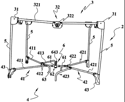
[0019] Referring to FIG 1, there is shown a collapsible frame 2 for a playpen
according
to the preferred embodiment of the present invention, wherein the playpen
includes an upper
frame assembly 3 and a lower frame assembly 4.
[0020] The upper frame assembly 3 consists of four upper corner housings 31
and a
pair of upper rail assemblies 32, wherein the upper corner housings 31 are
respectively arranged
at four corners of the playpen (for a triangular playpen there would be three
corners) and are
pivoted to the upper rail assemblies 32, respectively. The upper rail
assemblies consists of a pair
of rails 321 and a lock assembly 322, whereby the lock assembly 322 aligns the
rails 321 when
the collapsible frame 2 is in an unfolded state (as shown in FIG.1) and causes
the pair of rails 321
to form a V-shape when the collapsible frame 2 is in a folded state.
[0021] The lower frame assembly 4 includes a first lower frame assembly 41 and
a
second lower frame assembly 42, wherein the first and second lower frame
assemblies 41 and 42
are provided with a pair of lower corner bases 43 which are below a respective
pair of said upper
corner housings 31. An upright post 5 is connected between each upper corner
housing 31 and its
aligned lower corner base 43.
[0022] The first lower frame assembly 41 is connected to a lower end of the
upright
post 5 on one side of the playpen. In accordance with the present invention,
the first lower frame
assembly 41 includes a pair of connecting rods 411 and a connecting base 412,
wherein one end
of each of the pair of connecting rods 411 are pivotally coupled to a
respective said lower corner
base 43, and the other ends of the pair of connecting rods 411 are pivotally
coupled together at
the connecting base 412, so that the lower frame assembly 41 has a generally V-
shaped
configuration. As shown in this invention, a first supporting rod 413 is
additionally pivotally
coupled to said other end of the 10 connecting rod 411 and supports the
playpen over the ground.
[0023] The second lower frame assembly 42 is connected to a lower end of the
upright
post 5 on the other side of the playpen. According to this invention, the
second lower frame
assembly 42 has the same configuration of the first lower frame assembly, and
includes a pair of
connecting rods 421 and a connecting base 422, wherein one end of each of the
pair of
connecting rod 421 are pivotally coupled to a respective said lower corner
base 43, and the other
-3-
CA 02580167 2007-03-01
ends of the pair of connecting rods 421 are pivotally coupled together at the
connecting base 422
so that the second lower frame assembly has a generally V-shaped
configuration. As shown in
this invention, a first supporting rod 423 is additionally connected to said
other end of the
connecting rod 421.
[0024] Referring now to FIGS. 1, 2 and 8, a control device 6 is pivotally
connected
between the first and second lower frame assembly 41,42. The collapsible frame
2 includes a pair
of connecting rods 61, a joint 62 and a pair of second supporting rods 63. One
connecting rod 61
is coupled to, and between, the first lower frame assembly 41 and the joint
62, and the other
connecting rod 61 is coupled to, and between, the second lower frame assembly
42 and the joint
62.
[0025] As showing in FIGS. 3 to FIG. 5, an embodiment of the control device 6
according to the present invention, includes a pair of sleeves 621 and 621, a
positioner 622, a
button 623, resilient element 624, a driving element 64 and a string 643. The
pair of sleeves
621 are pivotally connected to one another and formed as a joint 62. Each of
the pair of sleeves
621 is connected with the connecting rod 61 and has a locking groove 625 for
accommodating
the positioner 622, and the positioner 622 is movable inside the locking
grooves 625.
[0026] According to the preferred embodiment of this invention, the positioner
622 is a
tooth block. As shown in FIGS. 3 and 4, the resilient element 624 is arranged
on one side of
the positioner 622. In the normal state, the resilient element 624 maintains
the positioner 622
between the locking grooves 625 of the pair of sleeves 621, and prevents the
sleeves 621 from
being folded by rotation.
[0027] The driving element 64 is pivotablly connected to one of the sleeve 621
at a
pivotal portion 626 formed thereon and having a pushing end 641 and a pulling
end 642. The
pushing end 641 of the driving element 64 is arranged for operatively abutting
on the button 623
for moving the positioner 622 against the biasing of the resilient element
624.
[0028] The pulling end 642 of the driving element 64 is operatively connected
with the
string 643. The user is able to pull the string 643 to rotate the driving
element 64 so as to press
the push-button 623 and force the positioner 622 to move into the locking
groove 625 of the
other sleeve 621, so that the sleeves are able to rotate as shown in FIG. 8 so
that the frame enters
a collapsible state.
[0029] The resilient element 624 in this embodiment can be a compression
spring and
the string 643 can be formed with a woven fabric. Preferably, the pushing end
641 of the
driving element 64 may be formed with extruded portion 6410 for operatively
contacted with the
center portion of the push-button 623, so as to keep the push-button 623
moving axiality without
-4-
CA 02580167 2007-03-01
causing unbalance. There is an alternative embodiment shown in FIGS 6 and 7,
wherein the
pushing end 641 of the driving element 64 is alternatively formed with a
length of extension end
6411 for operatively contacting with the center portion of the push-button
623.
[0030] As shown in FIGS. 1, 4 and 6, when the collapsible or foldable frame 2
is fully
extended, the positioner 622 of the joint 62 on the lower frame assembly 4 is
located inside the
locking grooves 625 of the pair of sleeves 621. As the entire collapsible base
frame 6 is in a fixed
state, the foldable frame 2 is also fixedly deployed.
[0031] As shown in FIGS. 5, 7 and 8, when the user requires the foldable frame
2 to be
folded, the string 643 is pulled. The push-button 623 is pushed by the pushing
end 641 of the
driving element 64 thereby to push the positioner 622 into the locking groove
625 of the other
sleeve 621. As the joint 62 is being folded by rotation, the first and second
lower frame
assemblies 41,42 are rotated as they are interlinked so that the lower frame
assembly 4 is able to
fold upwardly as shown as FIG 8.
[0032] A floor member and a flexible cover may be combined with the
collapsible
frame 2 to form a complete playpen.
[0033] While the invention has been described by way of example and in terms
of
preferred embodiments, it is to be understood that the invention is not
limited thereto. On the
contrary, it is intended to cover various modifications and similar
arrangements and procedures,
and the scope of the appended claims therefore should be accorded the broadest
interpretation so
as to encompass all such modifications and similar arrangements and
procedures.
-5-