Note: Descriptions are shown in the official language in which they were submitted.
CA 02580379 2007-03-09
WO 2006/031987 PCT/US2005/033010
1
One-Way Viewable Screen
Background of the Invention
Fencing is often utilized in a variety of situations to define property
boundaries, or to keep people, animals, and or objects inside or out of a
property. Conventional fencing is generally provided in two forms: two-way
viewable (where individuals on each side of the fencing can see through it) or
non-viewable (where individuals on each side of the fencing cannot see through
it, as in the case of privacy fencing.)
Similarly, screen and divider panels are conventionally provided to be
non-viewable, to block individuals on either side of the screen from seeing
clearly through to the other side. In some circumstances, one-way viewabW
screens or mirrors have been provided. In particular, one-way mirrors are
occasionally provided in some department stores, nurseries, and witness
questioning rooms so that the activities taking place inside the room can be
observed from others outside that room, without the people in the room being
observed being able to see their observers. One way see-through mirrors only
work when the light condition on one side is substantially greater than the
other.
As will be readily appreciated, such one-way glass mirrors are rigid and
fragile,
rendering them useful only in specific environments such as along a rigid
wall.
Other one-way viewable materials such as perforated vinyls, are designed
for situations where the lighting conditions on the two sides of the material
are
quite different. (For example, such materials are typically used on building
windows or automobile windows, where the light inside of the structure and
adjacent to one side of the material would be dramatically different from that
on
the outside of the structure, adjacent to the other side of the material.)
Those
panel materials typically have a see through open area of about 30 to 50%
comprising a plurality of relatively large openings (e.g. circular openings
about 1
mm in diameter.) However, they do not provide proper one-way see through
properties when lighting conditions on both sides are about the same.
CA 02580379 2007-03-09
WO 2006/031987 PCT/US2005/033010
2
Examples of such perforated vinyl, printed film and semitransparent
metallic coatings on glass used to provide one-way see through (from a low
light
intensity side, and non-see through from high light intensity side) are
described
in U.S. Patent Nos. 5,925,437, 6,258,429 and 4,673,609. As noted previously,
such materials do not provide one-way viewing when the lighting on both sides
of the material is approximately the same.
Summary
The present invention is directed to a fence, screen, divider or the like
which provides one-way viewing properties in situations where light conditions
on both sides of the structure are approximately the same. (As used herein,
such structures will be collectively referred to as "screens".) As noted
previously,
prior one-way viewing structures do not enable one-way viewing when the
lighting is approximately the same on both sides of the structure. In fact,
the
present inventors have found that the conventional materials have an optical
pathway equivalent to at least about 30 -50% light transmission (e.g., 1 mm
diameter holes spaced by 1.4 mm were found to be equivalent to about 40%
light transmission; 1/16 inch diameter holes spaced by 3/32 inch were found to
be equivalent to about 35% light transmission, by calculating the percent open
area and assuming transmission occurs only through that open area.) However,
it has been found that such high levels of light transmission fail to provide
the
non-see through property in one direction in equal lighting situations
regardless
of how reflective the material is. Preferably, the area of the openings in the
screen of the invention are smaller than the area of a 1 mm diameter circular
opening (i.e. 0.785 mm2. Openings of less than 0.2 mm2 are preferred (the area
of a 0.55 mm diameter circle), and openings 0.07 mm2 (the area of a 0.3 mm
diameter circle) are even more preferred. However, other sizes and shapes of
openings can be used within the, scope of the invention.
CA 02580379 2007-03-09
WO 2006/031987 PCT/US2005/033010
3
In addition to the advantage of providing one-way viewing under similar
lighting conditions on both structure sides, the invention can also be made to
have good air permeability and high mechanical strength, in most cases,
without
the need for a perforation manufacturing step. Because of these additional
properties, it has been found that the material has particular utility in
outdoor
fencing applications, where high winds may be encountered.
The screens are designed for optimal performance when the light intensity
is greater than 20 Lux. As noted, the screens of the invention work well when
the light intensity on both sides of the screen is approximately the same.
However, the screens also have been found to work well when the light
intensity
on the reflective side is greater than the light intensity on the highly light
absorbing (i.e. less reflective) side. It is to be noted that a range of light
transmission values and light reflection to light transmission ratios are
described;
as will be readily appreciated, the see-through and blocking performance are
affected by the light intensity. For example, a greater see through capability
is
generally achieved when the light intensity is brighter than when it is
relatively
low.
The screens of the invention desirably have a light transmission of about
2.8 to about 25% in the 400-700 nm spectrum (i.e. the visible spectrum.) The
screens also have a first side having an overall light reflectance to light
transmission ratio of > 2.5, and a second side having an overall light
reflectance
to light transmission ratio of < 2.
CA 02580379 2007-03-09
WO 2006/031987 PCT/US2005/033010
4
Brief Description of the Drawings
Fig. 1 is a perspective view of a screen according to the invention;
Fig. 2 is a photomicrograph of a woven version of a structure according to
the invention;
Fig. 3 is a photomicrograph of a knit version of a structure according to
the invention, illustrating an alternative distribution and size of openings;
Fig. 4 is a schematic representation of a screen in Fig. 1, illustrating the
light transmission, reflectance and absorption;
Fig. 5 is a cross-sectional view of an alternative embodiment of the
invention; and
Fig. 6 is a cross-sectional view of a tufted version of a fabric of the
invention; and
Fig. 7 is a cross-sectional view of a woven fabric according to the
invention..
Detailed Description
In the following detailed description of the invention, specific preferred
embodiments of the invention are described to enable a full and complete
understanding of the invention. It will be recognized that it is not intended
to limit
the invention to the particular preferred embodiment described, and although
specific terms are employed in describing the invention, such terms are used
in a
descriptive sense for the purpose of illustration and not for the purpose of
limitation.
CA 02580379 2007-03-09
WO 2006/031987 PCT/US2005/033010
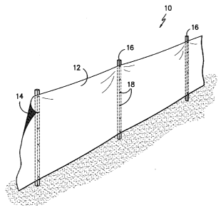
With reference to the drawings, Fig. 1 is a perspective representative of a
screen 10 according to the invention, which in this case is in the form of a
fence.
As illustrated, the fence includes supports 16, to which a material is secured
by
5 way of fasteners 18. (As will be readily appreciated by those of ordinary
skill in
the art, the screen can be constructed in any configuration or manner, with
Fig. 1
simply being generally representative of how a material can be oriented such
that it is exposed to substantially the same light on each of its two sides.)
The
screen 10 includes a first side 12 designed to be the non-see-through side,
and
a second side 14 designed to be the side that can be seen through. When this
screen is utilized under conditions of approximately equal lighting on each
side,
an observer looking at side 12 of the screen would not be able to see through
the screen, while an observer looking at side 14 would be able to see through
the screen.
As will be appreciated by those of ordinary skill in the art, an observer
looking at a structure such as a screen can only see things on the opposite
side
of the screen by virtue of the light that is transmitted through the screen
from the
opposite side. As shown in Fig. 4, each side of the material F is exposed to
substantially the same amount of light; therefore:
T1 = T2, and T2 + R2 + A2 = 100%, and T1 + R1 + Al = 100%, where
T1 = the light transmitted through side 12
R1 = the light reflected by side 12;
Al = the light absorbed by side 12;
T2 = the light transmitted through side 14;
R2 = the light reflected by side 14;
A2 = the light absorbed by side 14, since the amount of light is all either
transmitted through the screen, reflected back from the screen, or absorbed by
the screen.
CA 02580379 2007-03-09
WO 2006/031987 PCT/US2005/033010
6
The inventors have discovered that by engineering the fabric to have a
light transmission of about 2.8% to about 25% in the 400-700 nm spectrum, and
engineering the first side of the screen to have an overall light reflectance
to light
transmission ratio of > 2.5 and the second side of the screen to have an
overall
light reflectance to light transmission ration of < 2, a screen can be
achieved that
has good non-see through (i.e. blocking) characteristics on one side, and good
see through characteristics on the other side, under conditions where each
side
is exposed to substantially the same amount of light.
The invention is characterized by a textile structure having a light
transmission of about 2.8 - about 25% in the 400-700 nm spectrum. (For
purposes of this application, light transmission within the visible spectrum
is
obtained by measuring the light transmission at every 10 nm wavelength from
400-700 nm using a spectrometer in a conventional manner, with light
transmission and reflection being measured as a percentage of an incident
light
beam.) Even more preferably, the structure has a light transmission of about
15% or less in the 400-700 nm spectrum. In addition, the textile has two sides
with substantially different optical properties, where one side of the textile
has an
overall light reflectance to light transmission ratio of at least 2.5, and
preferably
about 5 or greater, and more preferably about 10 or greater, and the other
side
of the textile has the ratio of about 2 or less, and more preferably about 1.5
or
less. It is also highly preferred that the side with high reflectance have
minimal
light absorption while the other side has the maximum light absorption
possible.
(As noted previously, the total light is the sum of the light transmitted
through the
fabric plus the light reflected back by the fabric and the amount of light
absorbed
by the fabric. Therefore it follows that to maximize reflection, one would
seek to
minimize absorption.)
In addition to having a light transmission of about 2.8-25%, the size of
openings in the material is also desirably small (as noted previously), with
the
openings being relatively uniformly distributed across the whole material. It
has
CA 02580379 2007-03-09
WO 2006/031987 PCT/US2005/033010
7
found that this combination provides particularly good see-through properties.
When larger sized holes are used in combination with the above-described low
level of overall opening, fewer holes are needed and the holes would be
separated farther apart. As a result, it was discovered that an observer would
not be able to piece together the whole picture on the other side of the
material
from limited partial light transmission regardless of other optical properties
the
material may have. The size of opening therefore for this invention is
preferably
0.7 mm2 or less, and more preferably 0.07 mm2 or less, and the openings are
desirably substantially uniformly distributed across dimension of the material
designed to be see-through. In most cases, it would be desirable to have the
entire dimension of the structure be see through, in which case the openings
would be distributed across the entire dimension of the material. However, in
another aspect of the invention, see-through portions of material could be
provided adjacent areas that are not see through. For example, a grid
structure
formed of regions without openings could be formed to provide additional
strength to the material, provide a particular design, or the like.
The overall light transmission of about 2.8- 25% through the textile
structure is preferably achieved by controlling the yarn density such that the
openings between yarn interstices of the fabric structure provide the desired
level of light transmission. The textile can be of any variety, including
woven,
knit, or nonwoven. In a preferred form of the invention designed to perform
well
in environments where high strength is desired, a warp knit structure is
preferred. Alternatively, perforation, coating and printing can also be used
to
generate optical pathways or partially block optical pathways to control the
level
of light transmission. However, because perforation generates waste material,
and can significantly reduce the strength of the material, it would generally
not
be preferred for applications where high mechanical strength is required (e.g.
for
fence and barrier materials.)
CA 02580379 2007-03-09
WO 2006/031987 PCT/US2005/033010
8
Light reflection can be achieved using one or more of the following: a
white fiber/fabric surface; a coating on the fabric containing reflective
materials
such as titanium dioxide, zinc oxide, zirconium oxide, barium sulfate, calcium
carbonate, magnesium carbonate, calcium phosphate, mica, metal pigments
such as baluminum and brass; a metallic coating, such as sputtering or thermal
vapor deposition of aluminum on a textile structure, or electroless plating of
silver, chromium or similar reflective metals. Fibers with trilobal cross-
sections
or ribbon like fibers can also be used to provide high reflection.
Optical brighteners, other types of luminescent dyes and pigments can
also be incorporated on the highly reflective side of the fabric to provide
improved reflectance. Those materials can absorb UV light energy and emit the
energy as visible light, and thus provide improved brightness to a human's
eyes.
Low reflectance is achieved by dark color fabric surface, either by dyeing,
printing or coating with materials having high light absorption property. High
light
absorption can be achieved by using one or more of: dark color dyes, and/or
pigments such as carbon black, iron oxide, and graphite.
In one embodiment, the inventive textile structure is provided by forming a
textile structure using a warp knitting process, dyeing the fabric to a dark
black
color, and coating one side of the fabric with a reflective coating such as a
mixture of polyacrylic resin and titanium dioxide pigment. The warp knit
process
provides sufficient yarn density such that the light transmission through the
structure is 25% or less, the coating provides high overall reflectance on one
fabric side, and the black dye provides the high light absorption on the
opposite
surface. Alternatively, the fabric could be formed from previously-dyed or
solution dyed fibers, or be coated with a coating without being first dyed.
CA 02580379 2007-03-09
WO 2006/031987 PCT/US2005/033010
9
In another embodiment, a white or other light colored fabric is stitched,
laminated, or otherwise secured to a dark-colored highly light absorbent
fabric to
form a two layer composite, such that the overall composite has a light
transmission of 25% or less in the visible wavelength range, and reflectance
to
transmission ratio of at least 2.5 on the white fabric side and a ratio of
about 2 or
less on the dark colored fabric side. Fabric construction techniques can
utilized
to form such textile structure with minimal or no further processing. For
example, a reflective white or light colored yarn and a dark colored highly
light
absorbent yarn, for example, can be woven or knit into a fabric such that the
light
colored/white yarn is disposed predominantly on one side, while the dark
colored
yarn is disposed predominantly on the other side. The fabric would desirably
be
formed with a yarn density such that the overall light transmission through
the
finished fabric is less than about 25%. Alternatively, satin weave, dobby
weave,
jacquard weave, plain weave, basket weave, or the like can be used to weave a
single layer or double layer fabric wherein a light colored yarn is
predominantly
disposed on one side of fabric and a highly light absorbing dark colored yarn
is
predominantly disposed on the other side. For example, a white trilobal yarn
can
be used as a warp yarn and a solution dyed dark black yarn can be used as a
filling yarn in a satin weave such that the white warp yarn is predominantly
disposed on one side and the dark black yarn on the other. As a further
alternative, a knit fabric with a highly reflective side and a highly light
absorbing
side can also be formed by using warp knit, and double needle bar knitting. A
double layer fabric is preferred when weaving or knitting technique is used to
dispose reflective yarn on one side and light absorbing yarn on the other.
In yet another example which is illustrated in Fig. 5, a pile fabric is
formed,
where the pile yarn is a reflective light colored yarn, and the base yarn on
the
CA 02580379 2007-03-09
WO 2006/031987 PCT/US2005/033010
other side of the fabric is dark colored with high light absorbing property.
As
shown in Fig. 5, the fabric, shown generally at 20, includes a ground yarn
structure 22, and a pile formed from a plurality of fiber tufts 24. The pile
texture
on one side thus provide high overall light reflective feature, while the base
of the
5 fabric would have openings (between the yarns in the ground structure and
the
tufts) to facilitate see through the side of the fabric adjacent the ground
yarn
structure. The "cone" type of cross section (with the "cones" being formed
between adjacent pile tufts) of such fabric structure is desirable for
enhancing
one way see through. In addition, light absorbing coatings or the like could
be
10 provided on the ground yarn 22 and the portion of tuft yarn in contact with
the
ground yarn.
Fig. 6 illustrates the fabric shown in Fig. 5, with an opening 0 depicted,
which would be present between the yarns forming the fabric. Similarly, Fig. 7
illustrates a woven fabric, with an opening 0 illustrated as it would appear
between the adjacent yarns forming the fabric, and showing the different sides
12, 14 (as shown in Figs. 1 and 4.)
In yet another embodiment, a pattern of print and/or texture is further
provided on top of the highly reflective side. Such texture or print on a
reflective
surface would attract an observer to visually focus on the plane of such
surface
and omit the light transmit through the fabric. Such pattern can significantly
improve the non-see through property on the highly reflective side. Such
pattern
can be provided by printing, fabric construction, embossing, etching or the
like.
Photoluminescent or similar bright color print would be suitable for this
purpose.
Dark color print on highly reflective side, on the other hand, would diminish
the
reflectance and would not be desirable. Screening printing, ink jet printing,
air
brush, flexographic printing, electrostatic printing, and laser printing can
be used
to provide a printed pattern. Texture pattern can by formed by jacquard
CA 02580379 2007-03-09
WO 2006/031987 PCT/US2005/033010
11
weaving, double needle bar knitting, dobby weaving, patterned sanding, laser
etching, embossing and similar methods.
Light transmission and reflectance of such textile structure can be
measured using a light spectrometer, such as a Jasco V-570 spectrometer
available from Jasco, Inc. of Easton, Maryland, using an incident light of
visible
wavelength from 400 nm to 700 nm.
Other features such as infrared signature, infrared absorption, reflection,
and infrared fluorescence can also be incorporated to one or both side of the
fabric by using infrared reflective pigment, carbon black or infrared
absorbing/fluorescence dyes. In addition, designs can be printed, embossed,
painted, or otherwise provided on one or both of the fabric surfaces as
desired,
provided the pattern does not interfere to an extent that the respective
reflectance, transmission and absorbance cannot be achieved.
Examples:
Example 1: A plain warp knit fabric having 24 courses by 28 wales per inch was
formed by using 3 bars of 1/150/24 56T (meaning a 1 ply, 150 denier yarn with
24 filaments per yarn of Dacron type 56 round cross-section polyester yarn)
yarns and one bar of 1/100/34 56T background yarn. The fabric had a weight of
about 8.88 ounces per square yard. The intersticial openings of the fabric
varied
mostly in the range of 0.1 - 0.25 mm, and they are spaced from each other by
about 0.3 - 2 mm as shown in Fig. 3. The fabric was then jet dyed in a
conventional manner to a dark black color using black disperse dye such that a
low reflectance (approximately 4%) in the visible spectrum is achieved. The
fabric was then heat set in a conventional manner on a tenter frame. An
aluminum reflective pigment-containing metallic finish spray paint
manufactured
by Rust-Oleum Corporation was used to spray paint one side of the fabric such
CA 02580379 2007-03-09
WO 2006/031987 PCT/US2005/033010
12
that the side was covered with metallic paint. The coated fabric has an air
permeability of about 135 cfm at 125 Pa pressure using ASTM D737-96. The
fabric was fixed vertically in both indoor and outdoor locations such that
both
sides of the fabric were under similar illumination conditions. Observation
was
made from 10 to 20 feet away from the fabric from both sides to determine the
one-way see through property. The fabric provided good see-through property
from the uncoated black side, but substantially non-see through property from
the coated side when both side of the fabric was under equal lighting
conditions
either indoor or outdoor.
Example 2: The same warp knit fabric as used in Example 1 was instead dyed
with off-white cream color using disperse dyes. The fabric was then heat set
in a
conventional manner on a tenter frame. One side of the fabric was then spray
painted with metallic reflective coating using metallic finish spray paint
manufactured by Rust-Oleum Corporation (of the same variety used in Ex. 1),
while the other side of the fabric was coated with a dark black semi-flat
spray
paint of the variety manufactured sold under the tradename Krylon by Sherwin-
Williams, Inc. The coated fabric exhibited substantial non-see through from
the
metallic coating side and good see-through from the black coating side under
equal light condition on both side of the fabric both indoor and outdoors when
tested in the same manner as described in respect to Example 1.
Example 3: The same off-white cream colored warp knit fabric from Example 2
was used. One side of the fabric was coated with a dark black semi-flat Krylon
spray paint. The black coating side provides highly light absorbing and good
see
through property. Interestingly, no reflective treatment is needed on the
other
side where off-white fabric surface is reflective enough to provide non-see
through property.
CA 02580379 2007-03-09
WO 2006/031987 PCT/US2005/033010
13
Example 4: A woven fabric was formed using a single 574 denier polyester
monofilament warp yarn and 535 denier single monofilament Nylon 6 filing yarn.
The.fabric is woven in a plain weave pattern with 34 picks per inch and 35
ends
per inch. A black coating was applied by using semi-flat Krylon black spray
paint
on one side. The other side is coating with a 1:1 ratio mixture of Mearlite
Ultra
bright UWA (manufactured by Engelhard Corporation) and a polyurethane latex,
Impranil 85UD (by Bayer Corp, leverkusen, Germany). Mearlite Ultra Bright
UWA is a water dispersion of titanium dioxide coated mica reflective pigment.
It
was found that this fabric did not have good non-see through properties from
the
reflective side, which it is believed by the inventors was due to the high
level of
openness. Due to the relative high openness of the fabric structure, the
resulting
fabric does not have good non-see through property from the highly reflective
side of the fabric although significantly less clear see through was observed
from
the reflective side. This can also be understood from the low 2.37 ratio of
reflection to transmission on the reflective side.
Example 5: A black activated carbon woven fabric, FM1/250 (manufactured by
Activated Charcoal International, in United Kingdom), was coated with a
metallic
finish spray paint manufactured by Rust-Oleum Corporation on one side only.
The black activated carbon fiber provided highly light absorbing property on
the
other side. The interstitices between warp and filing yarns provide the light
transmission property. The coated fabric has good one way see through
property in both indoor and outdoor lighting condition. The interstitial
opening of
the fabric had openings of about 0.2 - 0.35 mm (across the dimension of the
rectangular holes), and are spaced about 0.8 - 1 mm apart.
Example 6: A woven spun polyester fabric having 204 denier spun warp yarn
and 12 denier spun filing yarn, with a plain weave pattern at 55 picks per
inch
and 68 ends per inch was dyed dark black using black disperse dye. One side
of the fabric is then coated with metallic finish spray paint manufactured by
Rust-
CA 02580379 2007-03-09
WO 2006/031987 PCT/US2005/033010
14
Oleum Corporation. The fabric exhibited see through property only under
outdoor high intensity lighting conditions. The spun yarn texture and too low
level of light transmission made the fabric not suitable for one-way see
through
uses under low light intensity.
Light transmission and reflection measurement is made using a Jasco V-
570 visible/UV/NIR spectrometer. Only visible light transmission and
reflection
are made. The results are listed in the following tables. It was found that
the
Examples which exhibited a light transmission of about 2.8% and about 25%,
and a first side having an overall light reflectance to light transmission
ration of >
2.5, and a second side having an overall light reflectance to light
transmission of
<2 performed well at enabling see through from only one fabric side when the
both fabric sides were exposed to the same light conditions. Example #4
illustrates an upper limit of light transmission for non-see through from the
reflective side, and Example #6 illustrates a lower limit of light
transmission
needed for see through from the light absorbing side.
CA 02580379 2007-03-09
WO 2006/031987 PCT/US2005/033010
EXAMPLE 1- Results
Wavelength Transmission, Reflection on Reflection on Ratio - A Ratio - B
nm % side A, % side B, % side side
700 3.881 31.692 9.772 8.165936614 2.517907756
690 3.695 32.161 8.144 8.703924222 2.20405954
680 3.454 31.774 6.622 9.199189346 1.917197452
670 3.242 31.35 5.396 9.669956817 1.664404688
660 3.122 31.241 4.663 10.00672646 1.49359385
650 3.043 31.167 4.226 10.2421952 1.388761091
640 3.002 31.147 4.003 10.37541639 1.33344437
630 2.987 31.159 3.916 10.43153666 1.311014396
620 2.982 31.19 3.906 10.45942321 1.309859155
610 2.984 31.231 3.926 10.46615282 1.315683646
600 2.983 31.264 3.94 10.4807241 1.320817968
590 2.984 31.3 3.961 10.48927614 1.327412869
580 2.986 31.329 3.992 10.49196249 1.336905559
570 2.983 31.358 3.997 10.512236 1.339926249
560 2.977 31.371 3.969 10.53778972 1.333221364
550 2.973 31.391 3.962 10.55869492 1.332660612
540 2.972 31.408 3.97 10.5679677 1.335800808
530 2.967 31.422 3.951 10.59049545 1.331648129
520 2.954 31.404 3.917 10.6310088 1.325998646
510 2.952 31.429 3.926 10.64668022 1.329945799
500 2.951 31.459 3.949 10.66045408 1.338190444
490 2.946 31.477 3.953 10.68465716 1.341819416
480 2.938 31.495 3.956 10.71987747 1.346494214
470 2.94 31.556 3.974 10.73333333 1.35170068
460 2.956 31.747 4.002 10.73985115 1.353856563
450 2.967 31.905 4.032 10.75328615 1.358948433
440 2.949 31.785 4.025 10.77822991 1.364869447
430 2.924 31.684 3.998 10.83584131 1.367305062
420 2.921 31.761 4.04 10.87333105 1.383087984
410 2.913 31.714 4.112 10.88705802 1.411603158
400 2.919 31.797 4.25 10.89311408 1.455978075
Avera e 3.046677419 31.48929032 4.466129032 10.3802041 1.446584433
CA 02580379 2007-03-09
WO 2006/031987 PCT/US2005/033010
16
EXAMPLE 2- Results
Wavelength Transmission, Reflection on Reflection on
Ratio - A Ratio - B
nm % side A, % side B, %
700 3.021 32.772 3.579 10.84806356 1.184707051
690 3.108 33.54 3.666 10.79150579 1.17953668
680 3.1 33.656 3.636 10.85677419 1.172903226
670 3.066 33.576 3.592 10.95107632 1.171559035
660 3.061 33.66 3.591 10.9964064 1.173146031
650 3.053 33.747 3.59 11.05371765 1.175892565
640 3.046 33.826 3.591 11.10505581 1.178923178
630 3.04 33.905 3.591 11.15296053 1.18125
620 3.037 33.981 3.592 11.1890023 1.182746131
610 3.032 34.053 3.593 11.23120053 1.185026385
600 3.027 34.126 3.595 11.27386852 1.187644533
590 3.02 34.183 3.598 11.31887417 1.191390728
580 3.015 34.243 3.6 11.35754561 1.194029851
570 3.01 34.287 3.601 11.3910299 1.196345515
560 3.002 34.335 3.606 11.43737508 1.201199201
550 2.996 34.384 3.61 11.47663551 1.20493992
540 2.992 34.432 3.614 11.50802139 1.207887701
530 2.987 34.473 3.619 11.54101105 1.211583529
520 2.974 34.485 3.624 11.59549428 1.218560861
510 2.971 34.529 3.633 11.62201279 1.222820599
500 2.962 34.571 3.643 11.67150574 1.229912221
490 2.955 34.593 3.655 11.70659898 1.236886633
480 2.946 34.612 3.667 11.74881195 1.244738629
470 2.941 34.652 3.687 11.78238694 1.253655219
460 2.951 34.857 3.722 11.81192816 1.261267367
450 2.965 35.115 3.747 11.84317032 1.263743676
440 2.945 35.117 3.742 11.92427844 1.270628183
430 2.92 35.01 3.749 11.98972603 1.28390411
420 2.915 35.106 3.777 12.0432247 1.295711835
410 2.896 35.119 3.78 12.12672652 1.305248619
400 2.881 35.15 3.809 12.20062478 1.322110378
Average 2.994677419 34.32564516 3.648354839 11.46924561 1.219029019
CA 02580379 2007-03-09
WO 2006/031987 PCT/US2005/033010
17
EXAMPLE 3- Results
Wavelength Reflection on Reflection on
Transmission, % Ratio - A Ratio - B
nm side A, % side B, %
700 4.642 42.569 3.574 9.170400689 0.769926756
690 4.715 43.54 3.649 9.234358431 0.773913043
680 4.681 43.756 3.606 9.347575304 0.770348216
670 4.623 43.592 3.568 9.429374865 0.771793208
660 4.605 43.679 3.564 9.485124864 0.773941368
650 4.586 43.769 3.557 9.5440471 0.775621457
640 4.568 43.855 3.553 9.600481611 0.777802102
630 4.55 43.945 3.549 9.658241758 0.78
620 4.531 44.044 3.547 9.720591481 0.782829397
610 4.512 44.138 3.543 9.782358156 0.785239362
600 4.491 44.265 3.541 9.856379426 0.788465821
590 4.475 44.387 3.539 9.918882682 0.790837989
580 4.456 44.47 3.538 9.979802513 0.793985637
570 4.432 44.492 3.535 10.03880866 0.797608303
560 4.404 44.512 3.532 10.1071753 0.801998183
550 4.386 44.596 3.532 10.16780666 0.805289558
540 4.364 44.723 3.534 10.24816682 0.809807516
530 4.342 44.823 3.536 10.32312298 0.814371257
520 4.314 44.87 3.536 10.40101994 0.819656931
510 4.289 45.017 3.54 10.49591979 0.825367218
500 4.267 45.149 3.546 10.58097024 0.831028826
490 4.239 45.193 3.553 10.66124086 0.83816938
480 4.209 45.207 3.561 10.74055595 0.846044191
470 4.182 45.276 3.577 10.82639885 0.855332377
460 4.17 45.594 3.608 10.93381295 0.865227818
450 4.159 46.009 3.629 11.06251503 0.872565521
440 4.115 46.07 3.616 11.19562576 0.87873633
430 4.062 45.956 3.62 11.3136386 0.891186608
420 4.034 46.051 3.642 11.41571641 0.902825979
410 3.967 45.844 3.64 11.5563398 0.917569952
400 3.909 45.411 3.655 11.61703761 0.935021745
Average 4.36383871 44.67103226 3.571612903 10.27140294 0.820726195
CA 02580379 2007-03-09
WO 2006/031987 PCT/US2005/033010
18
EXAMPLE 4- Results
Wavelength Reflection on Reflection on
Transmission, % Ratio - A Ratio - B
nm side A, % side B, %
700 27.302 65.82 16.763 2.410812395 0.613984323
690 26.998 65.826 16.559 2.438180606 0.613341729
680 26.893 65.706 16.359 2.443238017 0.608299558
670 26.836 65.349 16.046 2.43512446 0.597928156
660 26.76 65.081 15.766 2.432025411 0.58916293
650 26.651 64.791 15.462 2.431090766 0.580165847
640 26.52 64.494 15.09 2.431900452 0.569004525
630 26.399 64.133 14.639 2.429372325 0.554528581
620 26.268 63.727 14.087 2.426031674 0.536279884
610 26.113 63.34 13.524 2.425611764 0.51790296
600 25.994 62.939 13.077 2.421289528 0.503077633
590 25.914 62.617 12.827 2.416338659 0.494983407
580 25.887 62.286 12.697 2.406072546 0.490477846
570 25.838 61.926 12,563 2.396702531 0.486221844
560 25.787 61.556 12.423 2.387094272 0.481754372
550 25.726 61.258 12.336 2.3811708 0.479514888
540 25.681 60.981 12.304 2.374557066 0.479109069
530 25.666 60.735 12.338 2.366360165 0.480713785
520 25.626 60.464 12.365 2.359478654 0.482517755
510 25.6 60.23 12.365 2.352734375 0.483007813
500 25.558 59.927 12.311 2.344745285 0.481688708
490 25.515 59.627 12.203 2.336939055 0.478267686
480 25.473 59.35 12.078 2.329917952 0.474149099
470 25.403 59.058 11.958 2.324843522 0.470731803
460 25.251 58.787 11.865 2.328105818 0.469882381
450 25.079 58.416 11.791 2.329279477 0.470154312
440 25.037 57.878 11.675 2.311698686 0.466309861
430 25.035 57.385 11.603 2.292190933 0.46347114
420 24.994 56.855 11.513 2.274745939 0.460630551
410 24.903 55.985 11.389 2.248122716 0.457334458
400 24.738 54.299 11.082 2.194963214 0.447974776
Average 25.85306452 61.31696774 13.19541935 2.370346421 0.509115216
CA 02580379 2007-03-09
WO 2006/031987 PCT/US2005/033010
19
EXAMPLE 5- Results
Wavelength Reflection on Reflection on
Transmission, % Ratio - A Ratio - B
nm side A, % side B, %
700 3.734 34.063 3.167 9.122388859 0.848152116
690 3.688 34.209 3.148 9.275759219 0.853579176
680 3.67 34.423 3.164 9.379564033 0.862125341
670 3.68 34.469 3.147 9.366576087 0.855163043
660 3.681 34.548 3.128 9.385493073 0.849769084
650 3.687 34.617 3.117 9.388934093 0.845402766
640 3.689 34.689 3.106 9.403361345 0.841962591
630 3.687 34.759 3.088 9.42744779 0.837537293
620 3.697 34.811 3.07 9.416012984 0.830403029
610 3.702 34.851 3.055 9.414100486 0.825229606
600 3.706 34.919 3.037 9.422288181 0.819481921
590 3.71 34.967 3.032 9.425067385 0.817250674
580 3.71 35.015 3.013 9.438005391 0.81212938
570 3.714 35.054 3.001 9.438341411 0.808023694
560 3.716 35.065 2.985 9.436221744 0.8032831
550 3.718 35.109 2.971 9.442980097 0.79908553
540 3.723 35.135 2.956 9.437281762 0.793983347
530 3.723 35.161 2.941 9.444265377 0.789954338
520 3.727 35.175 2.923 9.437885699 0.784276898
510 3.725 35.197 2.909 9.44885906 0.780939597
500 3.731 35.213 2.894 9.437952292 0.775663361
490 3.733 35.233 2.878 9.438253415 0.770961693
480 3.737 35.247 2.863 9.431897244 0.766122558
470 3.736 35.255 2.85 9.436563169 0.762847966
460 3.712 35.287 2.833 9.506196121 0.763200431
450 3.682 35.382 2.827 9.609451385 0.767789245
440 3.691 35.429 2.83 9.598753725 0.766729884
430 3.698 35.422 2.813 9.578691184 0.760681449
420 3.71 35.489 2.812 9.565768194 0.757951482
410 3.698 35.538 2.809 9.610059492 0.759599784
400 3.69 35.558 2.79 9.636314363 0.756097561
Average 3.706612903 35.00932258 2.972806452 9.445184989 0.802108966
CA 02580379 2007-03-09
WO 2006/031987 PCT/US2005/033010
EXAMPLE 6- Results
Wavelength Transmission, Reflection on Reflection on
Ratio - A Ratio - B
nm % side A, % side B, %
700 6.178 22.784 14.835 3.687924895 2.401262545
690 5.042 21.683 10.542 4.300476002 2.090836969
680 4.048 20.521 7.163 5.069416996 1.76951581
670 3.313 19.535 4.984 5.896468458 1.504376698
660 2.863 18.911 3.828 6.605309116 1.337059029
650 2.623 18.523 3.279 7.061761342 1.250095311
640 2.507 18.355 3.027 7.321499801 1.207419226
630 2.455 18.289 2.922 7.449694501 1.190224033
620 2.436 18.295 2.891 7.510262726 1.186781609
610 2.432 18.329 2.894 7.536595395 1.189967105
600 2.434 18.363 2.906 7.544371405 1.193919474
590 2.433 18.395 2.919 7.560624743 1.199753391
580 2.445 18.439 2.945 7.541513292 1.204498978
570 2.449 18.472 2.975 7.542670478 1.214781543
560 2.456 18.511 2.998 7.537052117 1.220684039
550 2.465 18.542 3.024 7.522109533 1.226774848
540 2.48 18.6 3.075 7.5 1.239919355
530 2.511 18.671 3.157 7.435682995 1.257268021
520 2.557 18.792 3.272 7.349237388 1.27962456
510 2.609 18.919 3.437 7.251437332 1.317362974
500 2.685 19.093 3.65 7.110986965 1.359404097
490 2.758 19.247 3.866 6.978607687 1.401740392
480 2.752 19.271 3.898 7.002543605 1.416424419
470 2.653 19.119 3.668 7.206558613 1.382585752
460 2.57 18.989 3.465 7.388715953 1.348249027
450 2.533 18.957 3.377 7.484011054 1.333201737
440 2.501 18.904 3.332 7.558576569 1.332267093
430 2.521 18.952 3.422 7.517651726 1.357397858
420 2.584 19.177 3.645 7.421439628 1.410603715
410 2.686 19.373 3.957 7.212583768 1.473194341
400 2.853 19.718 4.51 6.911321416 1.580792149
Average 2.833290323 19.08803226 4.124612903 7.00055179 1.383160842
5 As noted previously, it was discovered by the inventors that a screen
having a light transmission of about 2.8- about 25% at the 400-700 nm
spectrum,
and a first side having an overall light reflectance to light transmission
ratio of >
CA 02580379 2007-03-09
WO 2006/031987 PCT/US2005/033010
21
2.5, and a second fabric side having an overall light reflectance to light
transmission ratio of < 2 provided good see-through from one side and good
blockage (i.e. non-see through properties) from the opposite side.
This textile structure can be used in a variety of end uses including but not
limited to fences, barriers at building and road construction sites, to cordon
off
accident sites, as a security curtain or wall panel, room divider, or the
like.
In the specification there has been set forth a preferred embodiment of
the invention, and although specific terms are employed, they are used in a
generic and descriptive sense only and not for purpose of limitation, the
scope of
the invention being defined in the claims.