Note: Descriptions are shown in the official language in which they were submitted.
CA 02580609 2013-11-20
THIN FILM DEVICES FOR OCCLUSION OF A VESSEL
[001]
FIELD OF THE INVENTION
[002] This invention generally relates to medical
devices that are implantable within a human subject and
=that have occlusion capabilities that are especially
suitable for use as medical device plugs for defective or
diseased body vessels. These types of devices have porosity
characteristics, upon deployment, that are suitable for
enhanced occlusion or other therapeutic capabilities at
selected locations.
DESCRIPTION OF RELATED ART
[003] Medical devices that can benefit from the present
invention include those that are characterized by hollow
interiors and that are introduced endoluminally and expand
when deployed so as to plug up a location of concern within
the patient. These are devices that move between collapsed
and expanded conditions or configurations for ease of
deployment through catheters and introducers. The present
disclosure focuses upon occlusion devices for diseased
locations within vessels of the body, especially devices
sized and configured for implantation within the
vasculature, as well as devices for neurovascular use.
CA 02580609 2013-11-20
-2-
[004] A number of technologies are known for
fabricating implantable medical devices. Included among
these technologies is the use of thin films. Current
methods of fabricating thin films (on the order of several
microns thick) employ material deposition techniques.
These methods are known to make films into basic shapes,
such as by depositing onto a mandrel or core so as to make
thin films having the shape of the mandrel or core, such as
geometric core shapes until the desired amount has built
up. Traditionally, a thin film is generated in a simple
(oftentimes cylindrical, conical, or hemispherical) form
and heat-shaped to create the desired geometry. One
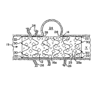
example of a known thin film vapor deposition process can
be found in Banas and Palmaz U.S. Patent Application
Publication No. 2005/0033418.
[005] Methods for manufacturing three-dimensional
medical devices using planar films have been suggested, as
in U.S. Patent No. 6,746,890 (Gupta et al.),
The method
described in Gupta et al. requires multiple layers of film
material interspersed with sacrificial material.
Accordingly, the methods described therein are time-
consuming and complicated because of the need to alternate
between film and sacrificial layers.
[006] For some implantable medical devices, it is
preferable to use a porous structure. Typically, the pores
are added by masking or etching techniques or laser or
water jet cutting. When occlusion devices are porous,
especially for intercranial use, the pores are extremely
small and these types of methods are not always
satisfactory and can generate accuracy issues. Approaches
such as those proposed by U.S. Patent Application
CA 02580609 2013-11-20
-3-
Publication No. 2003/0018381
include vacuum deposition of metals
onto a deposition substrate which can include complex
geometrical configurations. Microperforations are
mentioned for providing geometric distendability and
endothelialization. Such microperforations are said to be
made by masking and etching or by laser-cutting.
[007] An example of porosity in implantable grafts is
disclosed in Boyle, Marton and Banas U.S. Patent
Application Publication No. 2004/0098094, which is hereby
incorporated by reference hereinto. This publication
proposes endoluminal grafts having a pattern of openings,
and indicates that different orientations thereof could be
practiced. Underlying stents support a microporous
metallic thin film. Also, Schnepp-Pesch and Lindenberg
U.S. Patent No. 5,540,713
describes an apparatus for widening a
stenosis in a body cavity by using a stent-type of device
having slots which open into diamonds when the device is
radially expanded.
[008] A problem to be addressed is to provide an
occlusion device with portions having reversible porosities
that can be delivered endoluminally in surgical
applications, and implanted and positioned at a desired
location, wherein the porosities reverse from opened to
closed or vice versa to provide an immediate occlusive
function to "plug" the vessel defect and control or stop
blood flow into the diseased site, and to provide a
filtration function which allows adequate blood flow to
reach adjacent perforator vessels.
[009] Accordingly, a general aspect or object of the
present invention is to provide occlusion devices having
portions which perform a plugging function that
CA 02580609 2007-03-16
WO 2006/034114
PCT/US2005/033327
-4-
substantially reduces or completely blocks blood flow to a
diseased location of a blood vessel.
[0010] Another aspect or object of this invention is to
provide a method for plugging a vessel defect that can be
performed in a single endoluminal procedure and that
positions an occlusion device for effective blood flow
control into and around the area of the diseased location.
[0011] Another aspect or object of this invention is to
provide an improved occlusion device that incorporates thin
film metal deposition technology in preparing occlusion
devices which have porosities which may include pore
features that may move from opened to closed and vice
versa.
[0012] Another aspect or object of this invention is to
provide an occlusion device which substantially reduces or
blocks the flow of blood into or out of an aneurysm without
completely preventing blood flow to other areas including
adjacent perforator vessels or other features which can
benefit from relatively low blood flow.
[0013] Other aspects, objects and advantages of the
present invention, including the various features used in
various combinations, will be understood from the following
description according to preferred embodiments of the
present invention, taken in conjunction with the drawings
in which certain specific features are shown.
SUMMARY OF THE INVENTION
[0014] In accordance with the present invention, an
occlusion device is provided that has a carrying frame with
a thin film mesh structure extending over at least a
portion of the carrying frame and secured thereto. The
thin film mesh structure may cover the carrying frame, line
the interior of the carrying frame or the carrying frame
CA 02580609 2014-07-14
- 5 -
may be nested between two layers of thin film. The carrying
frame and the thin film mesh structure each have a contracted or
collapsed pre-deployed configuration which facilitates endoluminal
deployment as well as an expanded or deployed configuration within
the body. When deployed within the body, the occlusion device is
positioned so that the thin film mesh- structure acts as a plug
which substantially reduces or completely blocks blood flow to
the diseased portion of the blood vessel. For example, the
occlusion device is deployed so that the thin film mesh structure
covers or plugs the neck of an aneurysm.
[0014a] In accordance with an aspect of the present invention, there is
provided an expandable medical device having occlusion properties, comprising:
an elongated carrying frame having a defined length, said frame being
expandable from a collapsed condition to an expanded condition;
a thin film mesh secured to said elongated carrying frame; and
said thin film mesh has a plurality of openings therethrough that vary
in degree of openness as said carrying frame moves between said collapsed
condition and said expanded condition.
[0014b] In accordance with another aspect of the present invention, there
is provided an expandable medical device having occlusion properties,
comprising:
an elongated carrying frame having a defined length and surface area,
said frame being transformable between a collapsed condition to an expanded
condition;
a thin film mesh secured to said elongated carrying frame; and
said thin film mesh irrparts occlusion properties that vary along at
least a portion of the surface area of the carrying frame.
[0014c] In accordance with another aspect of the present Invention, there
is provided an expandable medical device having occlusion properties,
comprising:
an elongated carrying fra_me having a defined length, said
frame being expandable from a collapsed condition to an expanded
condition;
a thin film mesh secured to said elongated carrying frame; and
said thin film mesh has a plurality of openings therethrough
that vary in degree of openness as said carrying frame moves between
said collapsed condition and said expanded condition, the plurality
of openings include slits that open to slots as the carrying frame
CA 02580609 2014-07-14
- 5a -
moves from said collapsed to said expanded condition.
[001401] In accordance with another aspect of the present invention, there
is provided an expandable medical device having occlusion properties,
comprising:
an elongate carrying frame having a defined length, said frame
being expandable from a collapsed condition to an expanded
condition;
a thin film mesh secured to said elongate carrying frame and
said thin film mesh has a plurality of openings therethrough
that vary in degree of openness as said carrying frame moves between
said collapsed condition and said expanded condition;
wherein the thin film mesh is attached to the carrying frame
by spring arms arranged to hold the thin film mesh taut and in place
in the collapsed condition and in the expanded condition.
[0015] Porosity is provided in at least a portion of the thin
film mesh structure in the radially contracted configuration in
the form of pores or openings such as slots and/or slits that
are either generally open or generally closed. In a preferred
embodiment, at least some of the generally closed openings or
pores open substantially, or at least some of them close
substantially upon moving to the radially expanded or deployed
configuration, typically resulting in longitudinal
foreshortening of the thin film mesh structure.
[0016] In the embodiments where the openings or pores
are open, or have opened, in the deployed configuration, the
porosity is low enough to fully or partially occlude blood flow to
a diseased portion of the vessel being treated, but large enough to
allow passage of blood flow to adjacent perforator vessels. In the
embodiments where the pores are substantially completely closed in
the deployed configuration, the thin film mesh structure only
extends over a portion of the deployed carrying frame, and the
occlusion device is deployed so that the thin film mesh structure
only covers as much tissue as necessary to plug the diseased
portion of the blood vessel.
CA 02580609 2007-03-16
WO 2006/034114
PCT/US2005/033327
-6-
[0017] In making the thin film mesh, a core or mandrel
is provided which is suited for creating a thin film by a
physical vapor deposition technique, such as sputtering. A
film material is deposited onto the core or mandrel to form
a seemless or continuous three-dimensional layer. The
thickness of the film will depend on the particular film
material selected, conditions of deposition and so forth.
Typically, the core then is removed by chemically
dissolving the core, or by other known methods.
Manufacturing variations allow the forming of multiple
layers of thin film mesh material or a thicker layer of
deposited material if desired. It is also contemplated
that the thin film mesh structure could be made from a
suitable plastically deformable material, such as stainless
steel, platinum or other malleable metals, or a polymer.
[0018] Special application for the present invention has
been found for creating porous occlusion devices which have
a thin film mesh structure and selected porosity as
deployed occlusion devices, and methods also are noted.
However, it will be seen that the products and methods
described herein are not limited to particular medical
devices or methods of manufacture or particular surgical
applications.
BRIEF DESCRIPTION OF THE DRAWINGS
[0019] Fig. 1 is a front elevational view of an
occlusion device according to the present invention, in a
collapsed configuration;
[0020] Fig. 2 is a front elevational view of the
occlusion device of Fig. 1, in a deployed configuration
within a blood vessel;
CA 02580609 2007-03-16
WO 2006/034114
PCT/US2005/033327
-7-
[0021] Fig. 3 is a front elevational view of an
occlusion device according to an alternate embodiment of
the present invention, in a collapsed configuration;
[0022] Fig. 4 is a front elevational view of the
occlusion device of Fig. 3, in a deployed configuration
within a blood vessel;
[0023] Fig. 5 is a front elevational view of an
occlusion device according to yet another alternate
embodiment of the present invention, in a collapsed
configuration;
[0024] Fig. 6 is a front elevational view of the
occlusion device of Fig. 5, in a deployed configuration
within a blood vessel;
[0025] Fig. 7 is a front elevational view of an
occlusion device according to yet another alternate
embodiment of the present invention, in a collapsed
configuration;
[0026] Fig. 8 is a front elevational view of the
occlusion device of Fig. 7, in the deployed configuration
within a blood vessel;
[0027] Fig. 9 is a front elevational view of an
occlusion device according to yet another alternate
embodiment of the present invention;
[0028] Fig. 10 is a perspective view of an occlusion
device according to yet another alternate embodiment of the
present invention;
[0029] Fig. 11 is a perspective view of an occlusion
device of yet another alternate embodiment of the present
invention, in a collapsed configuration; and
[0030] Fig. 12 is a perspective view of the occlusion
device of Fig. 11, in a deployed configuration within a
blood vessel.
CA 02580609 2007-03-16
WO 2006/034114
PCT/US2005/033327
-8-
DESCRIPTION OF THE PREFERRED EMBODIMENTS
[0031] As required, detailed embodiments of the present
invention are disclosed herein; however, it is to be
understood that the disclosed embodiments are merely
exemplary of the invention, which may be embodied in
various forms. Therefore, specific details disclosed
herein are not to be interpreted as limiting, but merely as
a basis for the claims and as a representative basis for
teaching one skilled in the art to variously employ the
present invention in virtually any appropriate manner.
[0032] Fig. 1 illustrates an occlusion device 10 in a
collapsed position. The occlusion device 10 comprises a
carrying frame 12 and a thin film mesh structure 14 which
extends over and attaches to the carrying frame 12. The
thin film mesh structure 14 is preferably formed by
physical vapor deposition onto a core or mandrel, as is
generally known to those skilled in the art. Most
preferably, a thin film mesh structure of nitinol, or other
material which preferably has the ability to take on a
shape that had been imparted to it during manufacture, is
formed. When nitinol material is used in forming the thin
film mesh structure 14, the thin film mesh structure can be
at the martensite state. In addition, the mesh structure
when made of nitinol or materials having similar shape
memory properties may be austenite with a transition from
martensite to austenite, typically when the device is
raised to approximately human bodY temperature, or in the
range of about 95 F. (35 C.) to 100 F (38 C.).
[0033] In making the thin film mesh structure 14, the
selected material is sputter-deposited onto a core, which
core is then removed by chemical etching or the like.
Examples of this type of deposition are found in U.S.
Published Patent Application No. 2003/0018381, No.
CA 02580609 2013-11-20
-9-
2004/0098094 and No. 2005/0033418.
Nitinol, which encompasses alloys of
nickel and titanium, is a preferred film material because
of its superelastic and shape memory properties, but other
known biocompatible compositions with similar
characteristics may also be used. It is also contemplated
that the thin film mesh structure can be made of a suitable
plastically deformable material, such as stainless steel,
platinum or other malleable metals, or a polymer.
[0034] The thickness of the thin film mesh structure,
such as of structure 14, depends on the film material
selected, the intended use of the device, the support
structure, and other factors. For example, a thin film
mesh structure of nitinol is preferably between about 0.1
and 250 microns thick and typically between about 1 and 30
microns thick. More preferably, the thickness of the thin
film mesh structure is between about 1 to 10 microns or at
least about 0.1 microns but less than about 5 microns.
[0035] The occlusion device 10 is shown in Fig. 1 in a
collapsed configuration in which a plurality of pores or
longitudinally extending slits 16 disposed at least along a
portion of the thin film mesh structure 14 are
substantially closed. The longitudinally extending slits
16 may be formed by any known means, but are preferably
formed using laser-cutting. The slits 16 illustrated in
Fig. 1 are shown in an identical patterned configuration,
however the slits may assume differing profiles, e.g.
curvilinear, and may be arranged randomly or in selected
non-uniform patterns, according to the intended use.
[0036] The carrying frame 14 preferably comprises an
expandable stent which may take on many different
configurations and may be self-expandable or balloon
expandable. Examples of such stents are disclosed in U.S.
CA 02580609 2013-11-20
-10-
Patent Nos. 6,673,106 and 6,818,013, both to Mitelberg et
al.
Preferably the carry frame comprises an expandable stent
which is laser cut from a tubular piece of nitinol.
Alternatively, the carrying frame could also be a stent
made from a suitable plastically deformable material, such
as stainless steel, platinum or other malleable metals, or
a polymer.
[0037] In the embodiment illustrated in Figs. 1 and 2,
the thin film mesh structure 14 covers the entire carry
frame 12 in both the collapsed and expanded positions. In
other words, the thin film mesh structure 14 substantially
extends from one longitudinal end portion 18 of carry frame
12 to the other longitudinal end portion 20, and also
extends 360 degrees around the carrying frame. To maintain
full coverage of the carry frame 12, the thin film mesh
structure 14 is tacked to the longitudinal end portions 18,
20 of the carry frame at locations generally designated 22.
The thin film mesh structure 14 may be tacked to the carry
frame 12 by weld, solder or adhesive. Although Fig. i
illustrates tacking the thin film mesh structure 14 to the
longitudinal end portions 18, 20 of the carrying frame 12,
it will be understood that the thin film mesh structure 14
can be tacked at other locations along the carrying frame
12, depending on the desired use. Furthermore, it is
contemplated that under certain situations it will be more
advantageous for the thin film mesh structure 14 to line
the interior of the carrying frame instead of covering the
carrying frame.
[0038] As an alternative to tacking, the carrying frame
12 may be embedded or nested between separate layers of
thin film mesh structure. This may be accomplished by
sputtering a layer of thin film material onto a core. The
CA 02580609 2007-03-16
WO 2006/034114
PCT/US2005/033327
-11-
carrying frame is then placed or formed over the core
covered with thin film, and another layer of thin film can
be sputtered over the thin film covered core carrying the
carrying frame.
[0039] In use, the longitudinal slits 16 assist in
allowing the occlusion device 10 to expand radially and
foreshorten longitudinally. For example, Fig. 2 shows the
occlusion device of Fig. 1 when same assumes a
longitudinally foreshortened and radially expanded deployed
configuration 19 within a body vessel V. When implanted in
the body, the occlusion device 10, i.e. the carrying frame
and the thin film mesh structure, moves from the elongated,
collapsed configuration of Fig. 1 to the foreshortened,
deployed configuration 19 of Fig. 2.
[0040] When the occlusion device has been deployed to
the target area, the thin film mesh structure 14 expands
radially, and the slits 16 of this embodiment move from the
generally closed configuration slits 16 of Fig. 1 to the
generally open configuration slots 16a of Fig. 2. The
longitudinal ends 25, 25a of the slits 16 are compressed by
the force of the occlusion device moving to its deployed
configuration, causing the slits 16 to narrow and open,
thereby contributing to having the thin film mesh structure
14 foreshorten and radially expand. In the open
configuration, the slots 16a may assume a variety of open
profiles, such as the illustrated diamond-shaped openings,
depending on their initial closed profile. The open slots
16a are sized so that the thin film mesh structure 14 has a
low porosity which substantially reduces or completely
blocks the flow of blood into a diseased portion of a blood
vessel, such as aneurysm 24. However, the open slots 16a
are sized large enough to allow an adequate flow of blood
to perforator vessels 26. Additionally, the open slots 16a
CA 02580609 2007-03-16
WO 2006/034114
PCT/US2005/033327
-12-
can allow for tissue ingrowth and endothelialization for
permanent fixation of the occlusion device.
[0041] The radially expanded configuration of the
occlusion device as deployed in Fig. 2 is typically
achieved by heating a carry frame made of a nitinol thin
film mesh or other shape memory material when on a shaping
core or mandrel until it reaches an austenite condition,
whereby it is heat-set into the desired deployed shape and
size. Furthermore, when the thin film mesh structure 14 is
made from a nitinol or other shape memory material, it may
be heat set in a similar fashion. The set shape of the
carrying frame and the thin film mesh structure can be
offset when cooled and removed from the mandrel and
stretched down to a configuration such as shown in Fig. 1.
[0042] Typically, such memory "setting" is adequate to
achieve the desired expanded or deployed shape of the
device. However, the thin film mesh structure used in the
occlusion device may be so thin as to provide very little
expansion force or resistance to the expansive movement of
the carrying frame 12. Thus, the outward expansive force
of the carrying frame 12 may be the driver of the
transition from the pre-deployed configuration to the
deployed configuration of both the carrying frame 12 and
the thin film mesh structure 14. It also can be possible
to assist this expanded shaping by varying slot or slit
size, shape, and location in both the carry frame and the
thin film mesh structure.
[0043] For example, the elasticity of the thin film mesh
structure can be supplemented in a desired area by
overlapping portions of the thin film mesh structure with
relatively large slits that telescope to allow for enhanced
radial expansion when the occlusion device moves from a
collapsed configuration to a deployed configuration.
CA 02580609 2013-11-20
-13-
Alternatively, if even less radial expansion is required,
selected regions may be devoid of slits and slots, which
means that the amount of expansion which results is due to
the characteristics of the thin film material unaided by
slots or slits in the material.
[0044] The occlusion device 10 is configured and sized
for transport within a catheter or introducer of a delivery
system. A variety of delivery systems may be used to
deploy the occlusion device within a vessel of a patient.
The delivery system disclosed in U.S. Patent No. 6,833,003
to Jones et al.
is particularly useful in delivering an occlusion device
whose carry frame is a stent. In general, the occlusion
device 10 is placed at a downstream end of a catheter,
which catheter is introduced to the interior of a blood
vessel V. The downstream end is positioned adjacent to a
region of the blood vessel V which is to be occluded, and
then a plunger or pusher member ejects the occlusion device
into the target region. This may be achieved by moving the
pusher member distally, moving the catheter in a retrograde
direction, or a combination of both types of movement.
[0045] Preferably, the occlusion device 10 is comprised
of a shape memory material, such as nitinol, which will
move to a deployed configuration 19 upon exposure to living
body temperatures, as shown in Fig. 2. Once the occlusion
device 10 has been deployed, the catheter and plunger are
thereafter removed from the vessel V, and the occlusion
device is left at its deployed location.
[0046] The occlusion device 10 is deployed so that the
thin film mesh structure 14 plugs or covers the neck 28 of
the aneurysm 24. The open slots 16a are small enough to
substantially reduce blood flow into or out of the
aneurysm. This causes the blood within the aneurysm 24 to
CA 02580609 2007-03-16
WO 2006/034114
PCT/US2005/033327
-14-
stagnate and form an occluding thrombus. Additionally, the
open slots 16a are large enough to allow adequate blood
flow to surrounding perforator vessels 26. It also should
be noted that since the thin film mesh structure 14 covers
the entire carrying structure 12, the deployment accuracy
required may be less than with other prior art occlusion
devices. However, the occlusion device 10 may also include
radiopaque markers 30 to aid in proper deployment of the
occlusion device.
[0047] According to an alternate embodiment of the
present invention, referring to Figs. 3 and 4, the
occlusion device 10a has a thin film mesh structure 14a
which has a reversible porosity that is the opposite of the
embodiment illustrated in Figs. 1 and 2. In other words,
the thin film mesh structure 14a in the collapsed pre-
deployed configuration has a plurality of open pores or
slots 21 that close in the deployed configuration. These
open slots 21 are preferably cut in an axial pattern along
at least a portion of the thin film mesh structure 14a.
Upon deployment, as illustrated in Fig. 4, the thin film
mesh structure 14a expands radially and the slots 21 close
into circumferentially oriented slits 21a as the thin film
' mesh structure 14a foreshortens. When the slots 21 are
closed, the slits 21a are preferably at maximum density or
fully closed to block the flow of blood from flowing into
or out of a diseased portion of a blood vessel, such as
aneurysm 24.
[0048] In the collapsed or pre-deployed configuration
17a, the thin film mesh structure 14a may cover the entire
carrying frame 12a or a desired portion of the carrying
frame 12a. Additionally, the thin film mesh structure 14a
is tacked to the carrying frame at locations 32 which are
substantially inward of the longitudinal end portions 18a
CA 02580609 2007-03-16
WO 2006/034114
PCT/US2005/033327
-15-
and 20a of the carrying frame 12a. Tacking the thin film
mesh structure 14a and the carrying frame 12a in this
manner allows the thin film mesh structure to foreshorten
more than the carrying frame when the occlusion device is
in the deployed configuration 19a. This difference in
foreshortening results in having portions 34 of the
carrying frame 12a which are not covered by the thin film
mesh structure 14a. Preferably, in the deployed
configuration, the thin film mesh structure 14a covers
between about 40% and about 60% of the carrying frame 12a.
However, it is contemplated that the amount of coverage of
the carry frame may greatly vary from this preferred amount
depending on the intended use of the occlusion device.
[0049] In treating an aneurysm 24 within a blood vessel
V of a patient, the occlusion device 10a may be delivered
to the site of the aneurysm 24 using substantially the same
deployment devices and deployment techniques as described
above. In this embodiment, the odclusion device 10a is
deployed so that the expanded thin film mesh structure 14a
having closed slots 18a covers only the neck 28 of the
aneurysm 24 or an area slightly greater than the neck 28 of
the aneurysm 24. The thin film mesh structure 14a may
include radiopaque marks 30a to aid in deploying the
occlusion device 10a to the desired location. The thin
film mesh structure 14a plugs the aneurysm 24 and prevents
blood from flowing into or out of the aneurysm, causing the
creation of an occluding thrombus. Since the closed
slotted thin film mesh structure 14a only covers the neck
28 of the aneurysm 24 or an area slightly larger than the
neck 28 of the aneurysm 24, blood is allowed to flow
through the uncovered portions 34 of the carrying frame 12a
to provide an adequate blood supply to the perforator
vessels 26.
CA 02580609 2007-03-16
WO 2006/034114
PCT/US2005/033327
-16-
[0050] According to other alternative embodiments of the
present invention, referring to Figs. 5-10, the occlusion
devices 10b, 10c, 10d and 10e include areas of high mesh
density regions and areas of low mesh density regions. The
term "mesh density" refers to the level of porosity or the
ratio of metal to open area in a given portion of the
device. A portion of the occlusion device which is
considered a high mesh density region has approximately 40%
or more metal area and about 60% or less open area. The
mesh density, or ratio of metal area to open area, can be
controlled by the number and size of the openings or pores
and by the extent that the pores are open or closed in
situations where opening or pore openness varies between
delivery and deployment. It is preferred that the high
mesh density area be generally longitudinally centered
along the occlusion device, but it is also contemplated
that the high mesh density area may be positioned anywhere
along the occlusion device.
[0051] Referring specifically to Figs. 5 and 6, the high
mesh density area 36 of the occlusion device 10b is created
by centering a band of thin film mesh structure 14b on the
carrying frame 12b so that the thin film mesh structure 14b
extends 360 degrees around the carrying frame 12b but less
than the full longitudinal extent of the device. The thin
film mesh structure 14b is tacked to the carrying frame 12b
at locations 22b. The thin illustrated film mesh structure
14b also includes radiopaque markers 30b to aid in aligning
the high mesh density area in the desired location.
[0052] The occlusion device 10b is deployed to a blood
vessel V of a patient so that the high mesh density area
plugs a diseased portion of the blood vessel. For example,
referring to Fig. 6, the occlusion device 10b is deployed
so that the thin film mesh structure 14b providing a high
CA 02580609 2007-03-16
WO 2006/034114
PCT/US2005/033327
-17-
mesh density area plugs the neck 28 of an aneurysm 24. The
rest of the carry frame 12b is not covered by the thin film
mesh structure 14b and thus allows blood to flow to the
perforator vessels 26 or other areas thereat.
[0053] Referring to Figs. 7 and 8, the occlusion device
10c includes at least one portion of a high mesh density
area 36c and at least one portion of a lower mesh density
38. There are a variety of different ways to construct the
occlusion device 10c. For example, the occlusion device
10c may be constructed by covering the entire carrying
frame 12c with a low density thin film mesh structure 14c
and then adding an extra band of low density thin film mesh
structure 15 around the center of the occlusion device to
create an area 36c of high density thin film mesh
structure. Another possible method would be to center a
high density thin film mesh structure on the carrying
frame, and then place low density bands of thin film mesh
structure on the remaining uncovered portions of the
carrying frame.
[0054] Referring to Fig. 8, the occlusion device 10c is
deployed to a blood vessel V so that the high mesh density
area 36c of the thin film mesh structure plugs the neck 28
of aneurysm 24. The lower mesh density area 38 of the thin
film mesh structure preferably has a porosity that allows
adequate blood flow to adjacent perforator blood vessels 26
or other areas adjacent this area 38.
[0055] In yet another embodiment of the occlusion
device, referring to Fig. 9, a high mesh density area 36d
is created by placing a patch 14d of thin film mesh
structure on the carrying frame 12d. The longitudinal
length of the patch 14d and the extent to which the patch
14d extends around the carrying frame 12d may vary greatly
depending on the intended use of the occlusion device. It
CA 02580609 2007-03-16
WO 2006/034114
PCT/US2005/033327
-18-
will be noted the patch extends for less than 3600 of the
circumference. In the illustrated embodiment, this extends
less than 180 , on the order of 120 .
[0056] Fig. 10 illustrates an alternate embodiment of
the carrying frame. In Fig. 10, the occlusion device 10e
includes the carrying frame 12e which comprises a carrying
frame which can be a stent formed from a wire frame. A
patch 14e of thin film mesh structure is attached to wires
portions 40 and 40a of the stent. As with the embodiment
of Fig. 9, the mesh structure is shown in Fig. 10 extending
less than the full length and less than the full
circumferential extent of the device.
[0057] Another embodiment of the present invention is
illustrated in Figs. 11 and 12. In this embodiment, the
thin film mesh structure 14f is attached to the carrying
frame 12f by spring arms 42 and 42a. The spring arms 42
and 42a are preferably strands of elastic material, such as
nitinol or a polymer. Each spring arm 42 has a first
longitudinal end 44 and a second longitudinal end 46. Each
first longitudinal end 44 of spring arms 42 is attached to
the first longitudinal end portion 18f of the carrying
frame 12f, and each second longitudinal end 46 of the
spring arms 42 is attached to the first longitudinal end
portion 48 of the thin film mesh structure 14f.
Similarly, the first longitudinal end 44a of each spring
arm 42a is connected to the second longitudinal end portion
50 of the thin film mesh structure 14f, and the second
longitudinal end 46a of each spring arm 42a is attached to
the second longitudinal end portion 20f of the carrying
frame 12f.
[0058] Preferably, each spring arm 42 and 42a is equally
spaced apart from other adjacent spring arms around the
occlusion device 10f. The spring arm, 42 and 42a may be
CA 02580609 2007-03-16
WO 2006/034114
PCT/US2005/033327
-19-
attached to the carrying frame 12f and the thin film mesh
structure 14f by weld, solder, biocompatible adhesive or
other suitable biocompatible manner generally known in the
art. In the illustrated embodiment, attachment includes
using circumferential bands 52, 54, which may take the form
of shrink tubing or other type of banding, whether
polymeric or metallic. Same can be radiopaque if desired.
[0059] As illustrated in Fig. 11, when the occlusion
device 10f is in the collapsed or pre-deployed condition
17f, the spring arms 42 and 42a are in a collapsed
position. In this collapsed position, the spring arms 42
and 42a are under tension to hold the thin film mesh
structure 14f in place. Referring to Fig. 12, when the
occlusion device 10f is in the deployed configuration 19f,
the carrying frame 12f and the thin film mesh structure 14f
expand radially, and the thin film mesh structure 14f
foreshortens more than the carrying frame 12f. When the
thin film mesh structure 14f is in the deployed
configuration, the spring arms 42 and 42a are fully
extended so as to hold the thin film mesh structure 14f
taut and in-place.
[0060] When deployed in a blood vessel V of a patient to
treat an aneurysm 24, the carrying frame 12f and the thin
film mesh structure 14f expand radially, and the occlusion
device 10f is positioned so that the thin film mesh
structure 14f plugs or covers the neck 28 of the aneurysm
24, as illustrated in Fig. 12. As in the previous
embodiments, the thin film mesh structure 14f may include
radiopaque markers 30f to aid in deploying the occlusion
device 10f into the desired position.
[0061] It will be understood that the embodiments of the
present invention which have been described are
illustrative of some of the applications of the principles
CA 02580609 2013-11-20
-20-
of the present invention. Numerous modifications may be
made by those skilled in the art without departing from the
scope of the invention, including those
combinations of features that are individually disclosed or
claimed herein.