Note: Descriptions are shown in the official language in which they were submitted.
CA 02580658 2007-03-15
WO 2007/013878 PCT/US2005/032592
SYSTEM AND METHOD OF TRANSMITTING DATA
FROM AN AIRCRAFT
Field of the Invention
The present invention relates to communication
systems, and more particularly, the present invention
relates to a system and method of transmitting data from
an aircraft.
Background of the Invention
A Digital Acquisition Unit (DAU), also known by
some skilled in the art as a DFDAU, receives signals from
many on-board aircraft systems. The DAU processes the
data as Flight Operations Quality Assurance (FOQA) data,
which is recovered from the aircraft by different prior '
art techniques. For example, a PCMCIA card may connect
into an auxiliary PCMCIA slot of the Data Acquisition
Unit and record data into a flash memory of the card.
Once the data is collected into flash memory, airline
operators manually replace the PCMCIA cards with a new
card and retrieve the aircraft data from the flash memory
of the old card.
Other prior art techniques for collecting this
aircraft data include wiruless systems, which often
require costly aircraft modifications. For example, a
separate unit to record data, such as a ground data link
unit, is required, and an additional aircraft antenna
must be mounted on the fuselage. Often aircraft wiring
changes are made. These ground data link units require a
data processor, a data collection circuit, a wireless LAN
radio, a power amplifier, and external fuselage antenna.
Multiple line receiver units are also often required
-1-
CA 02580658 2010-12-22
adding to the significant investment made by an aircraft
operator.
Examples of ground data link systems that
have been used in an aircraft are disclosed in commonly
assigned U.S. Pat. Nos. 6,047,165; 6,104,914; 6,108,523;
6,148,179; 6,154,636; 6,154,637; 6,160,998; 6,163,681;
6,167,238; 6,167,239; 6,173,159; 6,308,044; 6,308,045;
6,353,734; 6,522,867; and 6,745,010.
It would be desirable, however, to extract
Flight Operations Quality Assurance data or other
aircraft data from an aircraft component, such as a DAU,
in a less complicated and costly system, rather than
using a ground data link unit or manually replacing flash
memory PCMCIA cards.
Summary of the Invention
The present invention advantageously provides a
turn-key solution in a removable PC card, which includes
a storage memory, control logic circuitry, a processor,
and a radio transceiver for transmitting aircraft data
along a radio frequency signal. In one aspect of the
present invention, the skin of the aircraft receives the
radio frequency signal and radiates the radio frequency
signal to a location remote from the aircraft, for
example, access points of a local area network. The
transmitter is preferably operative in accordance with
802.11 standards in which aircraft data is transmitted
over a spread spectrum communications signal, such as a
frequency hopping spread spectrum communications signal
- 2 -
CA 02580658 2007-03-15
WO 2007/013878 PCT/US2005/032592
or a direct sequence spread spectrum communications
signal.
The data can be transmitted to a Central
Maintenance Display Unit /CMDU), indicating in real-time
the health and status of aircraft systems. The data can
be flight performance data, such as Flight Operations
Quality Assurance (FOQA) data from the DAU, aircraft
engine data, in-flight entertainment data, or aircraft
data relating to aircraft contents, passenger data,
aircraft departure and arrival, passenger transactions,
or a sky marshall. The PC card preferably is formed as a
PCMCIA card with a desired form factor, for example, a
Type III PCMCIA card.
In one aspect of the present invention, the PC
card includes a PC card interface adapted for connecting
to an aircraft component, such as the DAU. A memory
stores aircraft data received from the aircraft
component. A radio transmitter receives the aircraft
data from the memory and transmits the aircraft data over
a radio frequency signal. A processor is operatively
connected to the PC card interface, memory and radio
transmitter for reading and forwarding data from the
memory to the radio transmitter. A logic circuit is
operative with the memory, processor and PC card
interface for controlling the downloading of data from
the aircraft component to the memory and the reading andt
the forwarding of data from the memory to the radio
transmitter without conflict between the processor and
aircraft component.
In one aspect of the present invention, the
logic circuit comprises a field programmable gate array.
-3-
CA 02580658 2007-03-15
WO 2007/013878
PCT/US2005/032592
The PC card body preferably has a PCMCIA form factor.
The transmitter preferably comprises a spread spectrum
transmitter for transmitting aircraft data over a spread
spectrum communications signal, which could be a
frequency hopping or direct sequence spread spectrum
communications signal. The PC card can also include a
receiver as part of a transceiver that receives data for
on-board processing. This type of received data could
comprise at least data for specifying one of the power
limits, frequency or type of aircraft data to be
transmitted.
Brief Description of the Drawings
Other objects, features anc4 advantages of the
present invention will become apparent from the detailed
description of the invention which follows, when
considered in light of the accompanying drawings in
which:
FIG. 1 is a block diagram showing an aircraft
Data Acquisition Unit and 'a prior art PCMCIA Type II
memory card interfaced with the Data Acquisition Unit,
and showing the different inputs from the Data
Acquisition Unit into the PCMCIA memory card.
FIG. 2 is a block diagram of the PC card of the
present invention, which interfaces with an aircraft
component, such as a Digital Acquisition Unit, and
showing a processor, logic circuit, memory and
transceiver.
FIGS. 3A, 35 and 3C are respective front
elevation, top plan and side elevation views of the PC
-4-
CA 02580658 2007-03-15
WO 2007/013878
PCT/US2005/032592
card of the present invention in a desired Type III
PCMCIA form factor.
FIG. 4 is a fragmentary, partial block diagram
of an aircraft having the PC card of the present
invention connected into an aircraft component, and
wirelessly transmitting aircraft data along a radio
frequency communications signals into the skin of the
aircraft, which radiates the radio frequency
communications signals to a wireless local area network
(LAN) access point (AP) to be processed at a server and
processor.
FIG. 5 is a block diagram showing various
aircraft components that can be interfaced with the PC
card of the present invention.
FIG. 6 is a graph showing a polar plot
superimposed on a regional jet for a 20 meter radiated
field test using the system of the present invention.
FIG. 7 is a graph showing a rectangular grid
superimposed on the regional jet used for the close-in
far field measurements using the system of the present
invention.
FIG. 8 is a graph showing a plot of the 20
meter radio frequency field readings using the system of
the present invention.
FIG. 9 is a graph showing the rationalized plot
of FIG. 8 data.
FIG. 10 is a three dimensional perspective view
of the near-skin data collected by using the system of
the present invention.
FIG. 11 is a plan view of the data shown in
FIG. 10.
-5-
CA 02580658 2007-03-15
WO 2007/013878 PCT/US2005/032592
FIG. 12 is a graph showing a two-curved plot of
the 20 meter and 2 meter data for comparison purposes.
FIG. 13 is a graph showing the representation
of 1/r and 1/r2 power roll off as a function of distance.
Detailed Description of the Preferred Embodiments
The present invention will now be described
more fully hereinafter with referencE to the accompanying
drawings, in which preferred embodiments of the invention
are shown. This invention may, however, be embodied in
many different forms and bhould not be construed as
limited to the embodiments set forth herein. Rather,
these embodiments are provided so that this disclosure
will be thorough and complete, and will fully convey the
scope of the invention to those skilled in the art. Like
numbers refer to like elements throughout, and prime
notation is used to indicate similar elements in
alternative embodiments.
The present invention automatically and without
manual intervention allows Flight Operations Quality
Assurance (FOQA) or other aircraft dEta to be extracted
from an aircraft component, such as the Digital
Acquisition Unit (DAU), into a PC card, without requiring
airline operators to manually replace the PC cards to
obtain the FOQA data, as in many prior art systems. The
present invention is also advantageous over prior art
wireless systems, which normally require costly aircraft
modification, including the use of a separate unit to
record aircraft data, an external aircraft antenna
mounted on the fuselage, and aircraft wiring changes.
-6-
CA 02580658 2011-10-24
The present invention uses a single PC card,
for example, a PC card operable in accordance with the
Personal Computer Memory Card International Association
(PCMCIA). The present invention uses the passive
radiation coupling of a radio frequency communications
signal into the skin of the fuselage, which radiates,
i.e., re-radiates the radio frequency communications
signal received from the PC card, which had radiated the
signal from its antenna, and eliminates the necessity for
adding an additional, external aircraft antenna mounted
on the fuselage.
Prior art systems include the use of a flash
memory PCMCIA card, or an integrated system such as the
ground data link systems disclosed in the above-
identified, commonly assigned patents. The ground data
link system disclosed in those patents sometimes require
multiple Local Receiver Units (LRU's) and a data
collection unit having a central processing unit, a
wireless local area network (LAN) radio, a power
amplifier, and an external fuselage antenna.
The ground data link unit as disclosed in the
above-identified patents operates with the ARINC 763
system, and is connected into the Data Acquisition Unit
(DAU) (also known as the DFDAU), typically through the
optional auxiliary output using an ARINC 429 link.
The Digital Access Unit system typically
includes a separate central processing unit (CPU) for a
mandatory portion or segment that connects by a ARINC 717
link to the Digital Flight Data Recorder (DFDR). The DAU
- 7 -
CA 02580658 2007-03-15
WO 2007/013878
PCT/US2005/032592
receives sensor information from the aircraft engines,
flaps, electronics and numerous other aircraft systems,
sometimes as many as 2,000 different systems in large
commercial aircraft. An optional portion of the DAU
typically includes a separate CPU and an
optional/auxiliary output, for example, formed as a
PCMCIA slot. The prior art multiple-LARU approach using
an external fuselage antenna and a ground data link unit,
or similar devices, typically required expensive
equipment acquisition and aircraft modifications. This
often required that the aircraft be out-of-service to
place the system in operation. Also, sometimes FAA
certification was required, which took time after or
before installation.
Although some prior art systems include a
standard PCMCIA Type II memory card interfaced to the
DAU, the card still had to be manually removed for data
retrieval. Other prior art systems used quick access
recorders having optical/magnetic media, which had to be
removed for data retrieval.
The present invention allows aircraft operators
to extract aircraft data, such as Flight Operations
Quality Assurance (FOQA) data, from the aircraft while
minimizing their costs of such retrieval.
The present invention uses a removable PC card,
such as a PCMCIA card, with a flash storage memory
circuit, control logic circuitry, a processor, wide local
area network (WLAN) radio drivers, and a complete 802.11
WLAN transceiver that transmits the aircraft data and
receives data for on-board processing. The use of a PC
card reduces cost to the aircraft operator without
-8-
CA 02580658 2007-03-15
WO 2007/013878
PCT/US2005/032592
requiring the aircraft to be out-of-service while a
system is installed. No external antenna is required
because the aircraft skin and fuselage acts as a passive
radiator, in accordance with the present invention, to
transmit or receive data from the aircraft. This can
optimize transmission from the aircraft and reduce
internal aircraft multipath attenuation.
FIG. 1 illustrates a conventional Digital
Acquisition Unit (DAU) 20 and a PC card designed as a
PCMCIA flash memory card 22 connected into the optional
PCMCIA connector 24 of the DAU, which interfaces an
auxiliary ARINC 429 link. This prior art PCMCIA memory
card 22 was typically a Type II memory card, and included
an ATA flash card controller 25 that connected into a
flash memory 26, and a regulator circuit 28. The ATA
standard is an AT attachment for a preferred IDE drive
interface on a PC card. The PCMCIA connector 24 on the
DAU 20 is formed as a 68-pin connector that connects to
the PCMCIA Type II memory card 22 as shown in FIG. 1.
The memory card typically has about 256 megabytes of
storage and a thickness of about 5 mm. FIG. 1 also shows
the various functions and data that can be extracted from
the DAU and input into the ATA flashcard controller 25.
FIG. 1 also shows the different connections to the flash
memory 26 from the ATA flashcard controller 25. The
chart below shows the pinouts and pin identification.
-9-
CA 02580658 2007-03-15
WO 2007/013878 PCT/US2005/032592
Pinouts
Pin Pin Pin Pin Pin Pin Pin Pin
No. Name No. _ Name No. Name No. Name
01 GND 18 RFU 35 GND 52 RFU
02 D3 19 RFU 36 /CD1 53 RFU
03 D4 20 RFU 37 Dll 54 RFU
04 D5 21 RFU 38 D12 55 RFU
05 D6 22 A7 39 D13 56 CSEL
06 D7 23 A6 40 D14 57 RFU
07 /CE1 24 AS 41 D15 58 RST
08 A10 25 A4 42 /CE2 59 /WAIT
09 /OE 26 A3 43 VS1 60 INPACK
RFU 27 , A2 44 /IORD 61 /REG
11 A9 28 Al 45 /IOWR 62 DASP
12 A8 29 AO 46 RFU 63 PDIAG
13 RFU 30 DO 47 RFU 64 D8
14 RFU 31 D1 48 RFU 65 D9
/WE 32 D2 49 RFU 66 D10
16 /IRQ 33 /1016 50 RFU 67 /CD2
17 VCC 34 GND 51 VCC 68 GND
5 Pin Identification
Symbol Function
DO - D15 Data Bus (bidirectional)
=
AO - A10 Address Bus (input)
/CE1, /CE2 Card Enable (input)
/OE, /WE Output / Write Enable (input)
/REG Register Select (input)
/IORD, /IOWR I/O Access (input;
/CD1, /CD2 Card Detect (output)
/IRQ, /1016, RST,
/WAIT, DASP, CSEL, I/O Handshaking (input/output)
PDIAG, INPACK
RFU Reserved for Future Use
VCC +5V or +3.3V power input
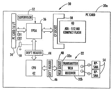
FIG. 2 is a block diagram of the PC card 30 of
10 the present invention, which includes a wireless
-10-
CA 02580658 2007-03-15
WO 2007/013878 PCT/US2005/032592
transceiver 32 for transmitting aircraft data, including
Flight Operations Quality Assurance (FOQA) data, and
receiving data for on-boald processing. The transceiverµ
32 includes respective transmitter and receiver sections
32a, 32b. FIGS. 3A, 33 and 3C show one form factor for
the PC card 30 of the present invention. The PC card
includes a body 30a formed as a PCMCIA Type III memory
card, which is about 10.5 mm thick and sufficiently large
enough to hold the additional circuitry, logic circuits,
controller (or processor), and transceiver used in the PC
card of the present invention.
As illustrated in FIG. 2, the PC card 30 of the
present invention includes a PC card-16 I/F interface
circuit 34. A Field Programmable Gate Array (FPGA) 36
circuit acts as logic circuitry to interface a CF socket
38, the ATA 512 megabyte compact flash memory 40, and the
interface circuit 34. The PC card 30 of the present
invention includes a central processing unit or processor
42, which interfaces through a development header circuit
44 with the field programmable gate array 36 and through
another development header circuit 46 to the wireless
local area network radio transceiver 32 via a radio
socket circuit 48.
A communication circuit 50 C01/CO2 interfaces
between the PC card interface 34 and the
data/communications bus on the development header
interface 44 between the central processing unit 42 and
the field programmable gate array 36. A supervisor
circuit 52 is operable with the field programmable gate
array 36 as a logic circuit and monitors the PC card
operation and its interface with the DAU 20 for
-11-
CA 02580658 2007-03-15
WO 2007/013878
PCT/US2005/032592
controlling the downloading of data from an aircraft
component to the memory, and the reading and forwarding
of the aircraft data from the memory to the radio
transmitter section 32a of the radio transceiver 32
without conflict between the processor and the aircraft
component. The supervisor circuit 52 and FPGA 36 permit
the disconnection of the CPU 42 in the PC card, and
allows the CPU in the DAU 20 to control data extraction
from the DAU into the ATA-512 megabyte compact flash
memory 40 of the PC card 30. The supervisor 52 and FPGA
36 allows the CPU 42 to read aircraft data from the
compact flash memory 26 and forward the aircraft data to
the transceiver 32, where the transmitter section 32a of
the transceiver wirelessly transmits the aircraft data as
a radio frequency communications signal into the skin of
the aircraft, which reradiates the radio frequency
communications signal to a location lemote from the
aircraft.
The PC card 30 can include two antenna
connections, RP-SMA 54, allowing connection of the
transceiver to small linear or other antennas about one
or two inches long. Preferably, a conformal antenna
would be used, conforming in design to the illustrated
Type III PCMCIA card, as one non-limiting example. It
should be understood that other form factors can be used
in the present invention besides the PCMCIA Type III form
factor. The transceiver 32 also includes a receiver
circuit 32b, which is operative to receive data for
specifying one of the power limits, frequency or type of
aircraft data.
-12-
CA 02580658 2007-03-15
WO 2007/013878
PCT/US2005/032592
In a preferred aspect of the present invention,
the WLAN wireless transceiver 32 is operable to transmit
aircraft data over a spread spectrum communications
signal, such as a frequency hopping or direct sequence
spread spectrum communications signal. Preferably the
transceiver 32 transfers the aircraft data over a radio
frequency signal that is in accordance with 802.11 family
of specifications for wireless LAN technology and, in one
aspect of the present invention, in accordance with
802.11(b), high rate or tbe Wi-Fi standard, which applies
to wireless LAN's and provides 11 Mbps transmission with
a fallback to 5.5, 2 and 1 Mbps in the 2.4 GHz band.
Preferably only a direct sequence spread
spectrum communications signal is used, but frequency
hopping spread spectrum communications systems can be
used in other embodiments, as well as other spread
spectrum systems, including modified chirp and similar
systems. The present invention also allows wireless
functionality, comparable to Ethernet. It should be
understood, however, that besides 802.11(b) protocol,
other 802.11 or other communication protocols, including
different types of complementary code keying (CCK) used
with direct sequence spread spectrum technology can be
used. The system could include Wired Equivalent Privacy
(WEP) by encrypting data and Wi-Fi Protected Access
(WPA), which improves security features of the Wired
Equivalent Privacy. The system can include improved data
encryption through a Temporal Key Integrity Protocol
(TKIP), which scrambles the keys using a hashing
algorithm and uses an integrity-checking feature. The
system can have user authentication through an Extensible
-13-
CA 02580658 2010-12-22
. .
Authentication Protocol (EAP), which together with WEP,
regulates access to a wireless network based on a
computer-hardware specific Media Access Controller (MAC)
address. EAP can be built on a secure public key
encryption system to ensure only authorized network users
access any local area or other network that receives the
aircraft data. Other types of frequency-shift keying or
phase-shift keying methods can be used for the present
invention.
FIG. 4 shows an aircraft 60 with the wireless
PC card 30 of the present invention incorporated with the
DAU 20. The PC card 30 transmits aircraft data along a
radio frequency communications signal into the skin 62 of
the aircraft fuselage, which radiates the radio frequency
communications signal to a location remote from the
aircraft. In the present illustrated example shown in
FIG. 4, the signal is transmitted to a wireless local
area network having multiple access points 66 acting as
receivers that connect through connection 64 into a
server 68, for example, a baggage server, and into a
processor 70, for example, a wireless laptop PC, which
allows processing of the aircraft data that is received
from the aircraft. For example, the aircraft data could
be data relating to what luggage is stored in the
aircraft. That luggage data is transmitted to the DAU 20
or another aircraft component. The PC card 30 of the
present invention extracts the aircraft data and stores
it in memory 40. The CPU 42 reads the aircraft data from
the PC card memory 40, forwards the aircraft data to the
transceiver 32, which transmits the aircraft data to the
skin of the aircraft. The radio frequency communications
signal is reradiated
- 14 -
CA 02580658 2007-03-15
WO 2007/013878
PCT/US2005/032592
(or radiated) from the aircraft skin as a passive antenna
to receivers on the ground as access points of the local,
area network.
Because the PC card 30 of the present invention
has a receiver 32b as part of its transceiver 32
function, data can be uploaded, including control signals
for specifying which portions of data are to be retrieved
from the aircraft component and transmitted. Also,
because the PC card of the present invention has a
desired form factor, for example, a Type III PCMCIA form
factor, the PC card can be connected into other PC card
slots for different aircraft components, including PC
card slots that may be positioned on the aircraft engine,
in the cockpit, in the cargo compartment, or in the main
passenger seating area.
FIG. 5 shows different aircraft components.
For example, the DAU 20, and a second aircraft component
80, both receive the PC card 30 of the present invention.
Data could be retrieved from a FADEC 82, software updates
84, an air marshall 86, or in-flight entertainment system
88 using the PC card of the present invention, depending
on which aircraft component it is coupled. Signals could
be received from an air marshall 86 who is stationed on
an international or other domestic flight, and later
transmitted to the ground or directly to the cockpit
using the PC card of the present invention, for example,
interfaced to the ADU or other aircraft component.
Aircraft data could also be transmitted to a Central
Maintenance Display Unit (CMDU) 90 that indicates in
real-time the health and status of aircraft systems. The
-15-
CA 02580658 2010-12-22
CMDU 90 could be located in the cockpit 92 to allow the
pilot to view real-time health and status data.
The aircraft data could also comprise flight
performance data or aircraft engine data received from a
WEMS module 94 mounted on the FADEC 82. An example of a
WEMS module is disclosed in commonly assigned U.S. patent
No. 6,943,699 B2 entitled "Wireless Engine Monitoring
System". Also, the aircraft data could be related to at
least one of aircraft contents, passenger data, aircraft
departure and arrival, or passenger transactions.
Aircraft data could also be received from a hand-held
unit, such as disclosed in the '010 patent. Data can be
transmitted to the flight deck if applicable.
It should be understood that the PC card 30
of the present invention can have other functions because
it includes a transceiver for receiving data for on-board
processing. This received data could be instructions for
varying the power or frequency of a transmission. Also,
various audio, video and navigation files could be
uploaded and transferred from the PC card into an
aircraft component, for example, an in-flight
entertainment file server or the DAU, and then into other
aircraft systems.
The PC card of the present invention can also
be operative for transmitting aircraft data at a first
higher data rate when the aircraft is on the ground, and
a second, substantially lower data rate when the aircraft
is airborne in close proximity to an airport, for
- 16 -
CA 02580658 2010-12-22
example, as disclosed in the above-identified '681
patent. It is also possible to transmit over a plurality
of sub-band frequency channels where the frequency can be
chosen based upon the position of the aircraft determined
by an on-board global positioning system, as disclosed in
the above-identified '238 patent. Flight management data
can also be uploaded. The PC card 30 of the present
invention could include the functions as disclosed in the
referenced patents.
The PC card 30 of the present invention is
also advantageous because it wirelessly transmits
aircraft data from the aircraft without requiring an
external antenna mounted on the fuselage. It has been
found that the aircraft skin can be used as a passive
radiator. As a result, it is possible to shorten the time
and decrease the effort used in the recovery of aircraft
data for off-site analysis. Experimental results have
shown the advantages of this system and method.
Experiments were conducted showing the
feasibility of using the aircraft skin by using an IEEE
802.11b wireless Local Area Network (LAN) card operating
in a PC card slot of a laptop computer. The aircraft used
was a Canadair CL-604 regional jet aircraft. The laptop
for this test was placed in a rear equipment bay, which
is outside of the pressure hull. It is vented to the
atmosphere through a set of louvers on the belly of the
aircraft. The laptop was set to run on its own battery
power for the duration of the test. The importance of
this fact is to note that there was no
- 17 -
CA 02580658 2007-03-15
WO 2007/013878 PCT/US2005/032592
coupling of the electrical systems (DC or RF) of the
aircraft and the laptop cnmputer. The laptop was set to
perform a "ping" operation continuously to provide a
steady stream of packets for the Radio Frequency (RF)
measurements.
The tests consisted of two parts. The first
test was a series of measurements taken at a distance of
20 meters from the center of the aircraft (FIG. 6). The
measurements were spaced 15 degrees apart with zero
degrees centered on the nose of the aircraft. The second
set of measurements was taken at a uniform distance of 2
meters from the closest approach to the skin of the
aircraft and spaced 3 meters apart (FIG. 7).
The measurement equipment included an Agilent
model 8563 EC spectrum analyzer connected through a 6
meter cable to a 2.4 GHz test antenna. The antenna was
mounted on a nonconductive pole approximately 2 meters
long. This height placed it at the outer bulge of the
aircraft skin and above the level of local sources of
multi-path and other unintentional re-radiators.
The first 20 meter test was intended to
ascertain the far field pattern of radiation within the
available ramp space of the airport while at a reasonably
large distance from the aircraft. The second 2 meter
test was intended to examine the close-in far field for
point-like or line-like radiators which would contribute
disproportionately to the far field pattern or conversely
eliminate them as major contributors.
FIG. 6 is a polar plot superimposed on a CL-604
regional jet for the 20 meter radiated field test, and
illustrates the geometry for the 20 meter data collection
-18-
CA 02580658 2007-03-15
WO 2007/013878
PCT/US2005/032592
effort. The aircraft is approximately 21 meters long
overall and 19 1/2 meters wingtip-to-wingtip. Thus, the
first measurement was, in general, 20 meters or more from
the closest point of approach to the aircraft skin.
FIG. 7 illustrates the superposition of a
rectangular grid over the outline of the CL-604 aircraft
for close-in fair field measurements and the transposed
data points collected to determine if any strong, point-
source radiators existed to account for the far field
radiation pattern. These measurements used the same data
collection equipment as that used in the first test.
Each circle represents one point of measurement.
The data from the first test (20 meter) was
tabulated and plotted in a polar format below as later
shown in the graph of FIG. 8. The angular dimension
represents the stepwise progression of data points
beginning with the nose of the aircraft at 0 degrees.
The radial dimension represents the received RF power in
dBm at 20 meter distance at the indicated angle. Due to
this representation of data it may appear somewhat
counterintuitive that the most distant points have
reduced power readings. FIG. 9 corrects this perceptual
preference and shows a rationalized polar plot of FIG. 8.
That plot does not attempt to scale exactly the power
readings, but show the relative amplitudes for
comprehensibility. The tabulated data as reflected in
FIGS. 8 and 9 are shown in the table below:
-19-
CA 02580658 2007-03-15
WO 2007/013878
PCT/US2005/032592
r O=deg 86.4"
15=deg 83.37
30. deg 84.53
45. deg 84.03
60. deg 82.53
75. deg 83.03
90. deg 82.53
105. deg 77.03
120. deg 80.2
135=deg 81.53
150-deg 75.70
165. deg 77.03
Chl := 180. deg 75.53 *
195. deg 77.2
210=deg 78.87
225. deg 75.53
240. deg 81.20
255. deg 82.37
270. deg 80.53
285. deg 86.03
300= deg 87.37
315=deg 85.37
330=deg 87.87
345. deg 83.53
360=deg 86.4)
:= Chi(0)
r := Chi(1)
I .= (-Chi)K1
1
1
(1)
Chi
12 = .= I2 = 1000
-20-
CA 02580658 2007-03-15
WO 2007/013878 PCT/US2005/032592
0
0 -86.4
1 -83.37
2 -84.53
3 -84.03
4 -82.53
-83.03
6 -82.53
I = 7 -77.03
1
8 -80.2
9 -81.53
-75.7
11 -77.03
12 -75.53
13 -77.2
14 -78.87
-75.53
0
0 11.574
1 11.995
2 11.83
3 11.901
4 12.117
5 12.044
6 12.117
I2 = 7 12.982
8 12.469
9 12.265
10 13.21
11 12.982
12 13.24
13 12.953
14 12.679
15 13.24
The smooth nature of the curve depicted in
5 FIGS. 8 and 9, with no extreme peaks or valleys, suggests
either a large number of evenly distributed emitters on
-21-
CA 02580658 2007-03-15
WO 2007/013878 PCT/US2005/032592
the fuselage of the aircraft, or alternatively, that the
body or skin of the aircraft is the predominant source of
the radiation. The conclusion that the body (skin) of
the aircraft is the predominant source of radiation is
reinforced by the small, uniform increase in amplitude in
the rear hemisphere.
The RF field data from the second set of
measurements for the close-in portion of the far field
was plotted on a rectilinear graph based on a scaled
image of the aircraft obtained from the manufacturer's
maintenance manual. This transposition is shown above in
FIG. 7. These data points were then incorporated in a 22
by 2 matrix, which provided a two dimensional
representation of the area around the aircraft. The raw
data for the non-zero matrix entries is shown below. The
matrix subscripts are the x and y positions of the data
point and the value of the matrix entry is the RF power
expressed in dBm.
Ch27, 13 =.= -86.33
Ch23, 16 === -81.17
Ch20, 16 := -80.50
Ch17,17 := -87.67
Ch14, 22 := -83.00
Ch12, 26 =.= -80.67
= -83.00
Ch9, 28 . =
-22-
CA 02580658 2007-03-15
WO 2007/013878
PCT/US2005/032592
Ch8,23 =.= -76.00
Ch9,21 =.= -75.67
Ch10,18 := -75.67
Ch8,18 := -71.83
Ch5,16 := -64.50
Ch0,13 :=-74.83
Ch5,10 := -68.17
Ch9,9 := -64.33
Ch9,7 := -71.17
Ch8,3 := -81.33
Ch8 0 .= -83.67
,
Ch14,2 := -78.5
Ch16, 6 := -81.67
Ch17, 9 := -83.00
Ch22,9 := -79.50
The data in this matrix has been plotted in a
three dimensional representation, which is presented in
two views. The first view shown in FIG. 10 as a three
dimensional perspective view of the near-skin data to
assist visualization of the field strength measurements
-23-
CA 02580658 2007-03-15
WO 2007/013878 PCT/US2005/032592
in relation to the aircraft. The second view shown in
FIG. 11 is a plan view of FIG. 10, which aids in helping
to determine a reasonable accuracy of the data
positioning and the aircraft orientation.
Based upon these results, it was possible to
create a direct comparison between the two field plots
either mathematically, graphically or both. This was
accomplished by converting the rectilinear coordinates of
the near-skin plot to polar coordinates and plotting the
data in two curves on one polar plot. Data for the
results is shown below and a two curve plot of the 20
meter and 2 meter data for comparison purposes is shown
in FIG. 12 for comparison purposes.
-24-
CA 02580658 2007-03-15
WO 2007/013878
PCT/US2005/032592
( 13.5 0.0
2.8
6.5 3.5
4.25 3.5
1.25 9.0
-0.5 12.5
-3.5 14.5
-5.2 10.3
-4.0 7.5
-2.8 4.8
-4.8 4.8
V :=
-8.25 2.8
-12.8 0.0
-8.25 -3.0
-4.0 -4.25
-4.0 -5.75
-5.25 -10.0
-5.25 -13.25
1.25 -11.25
3.00 -7.0
4.25 -4.25
9.0 -4.25
-25-
CA 02580658 2007-03-15
WO 2007/013878
PCT/US2005/032592
(86.33\
81.17
80.50
87.67
83.00
80.67
83.00
76.00
75.67
75.67
71.83
P :=
64.5
74.83
68.17
64.33
71.17
81.33
83.67
78.5
81.67
83.00
79.5j
1:= 0,1.. 21
j := O.. 1
R. := P.
1 1
In FIG. 12 and in the data represented above,
the quantities i and j are indices for the polar data
plot and the change of variable from P to R is for
convenience. The function 91 and "angle()" create a set
of angular coordinates from a pair of rectilinear
coordinates by returning the angle from the positive x
axis of the coordinate pair. This function operates from
-26-
CA 02580658 2007-03-15
WO 2007/013878 PCT/US2005/032592
0 to 2n. The radial coordinates are in dBm from zero at
the origin to 87.87 dBm at the periphery. As before, the
dBm are actually -dB from the value at the transmitter.
( (0) (1))
:= angle[ ,\V
The two curves indicate the possible mechanisms
for the RF radiation pattern from the aircraft. Certain
points of interest are: (a) neither curve exhibits
significant variability as would be the case if the
sources were a small number of discreet emission sources;
(b) the two curves almost overlay one another forward of
the wing area, the region farthest from the internal RF
source. They are not grossly divergent aft of the wing
area; and (c) the power level of the radiation is not
decreasing at the rate of a point source, i.e., 1/r2, it
is more like the emission from a line source, l/r.
Two credible mechanisms to explain the RF
radiation patterns are: (1) a large number of discreet
emitters distributed fairly uniformly around the
aircraft; or (2) the excitation of the aircraft skin with
concomitant radiation of a uniform nature, tailing off
only as a result conduction losses in the skin as the
surface wave moves from the source area aft to the
forward area. A third possibility is, of course, a
combination of these two mechanisms.
The possibility of discrete sources distributed
over the aircraft skin was explored and discarded. Two
areas of possible strong radiation from openings were
also examined to determine if any fuselage opening
account for the strength of RF emissions. The cockpit
windows and the louovered hatch into the aft equipment
-27-
CA 02580658 2007-03-15
WO 2007/013878 PCT/US2005/032592
bay containing the laptop was examined. Placing the
antenna directly in front of the cockpit window produced
no change in the measured field as compared to 2 or 20
meters directly forward of the nose. A double layer of
metalized mylar sheeting was placed over the louvers in
the aft hatch and prior readings were repeated. An
approximately 1 dB drop in received power level was
observed.
The relatively smooth and similar measurements
t 10 at the two distances indicate a reasonably uniform source
for the radiated energy, both by way of the lack
discontinuities and from the lack of a 1/r2 behavior of
the power readings.
The field from an infinite conducting plate
does not fall off as a function of distance. If two
opposing edges of the plate are brought together to form
an infinitely long conducting line, the power falls of as
l/r, and further, that if the ends of the line are shrunk
down to point, then the power falls off as 1/r2. This is
illustrated in FIG. 13, which has been constructed to
reflect the measurements obtained from the aircraft.
FIG. 13 is a graph representative of l/r and 1/r2 power
roll off as a function of distance. One line is 1/r2 and
another line is 1/r. The horizontal lines represent the
nominal sensitivity of the wireless NIC at the indicated
data rates. It should be noted that the 1/r curve
appears to fit the measured data more closely than the
other curve.
The minor extrapolation of the curve to
aircraft skin surface shows a source strength of -35 dBm.
The actual source inside the aircraft is generating
-28-
CA 02580658 2007-03-15
WO 2007/013878
PCT/US2005/032592
approximately +15 dBm, and thus, it appears that there is
a 50 dB loss in coupling to the skin, 'which is a
reasonable number. Based on the available data and this
informal ad hoc measurement methodology, it is not
unreasonable to assume that the aircraft is a combination
finite line and, to a lesser degree, a finite curved
surface emitter which would allow prediction of the
behavior of other aircraft models and types.
These measurements make it clear that a
broadband, digital communication system can be installed
in the avionics bay of any aircraft and, without having
to mount external anntenna, communicate reliably with the
terminal offices at operationally useful distances. Some
experiments were also conducted on several different
models of commercial aircraft to begin answering some of
these tests involved placing'a laptop within the avionics
bay of different aircraft, closing up the aircraft and,
using a second laptop, determine the distance away from
the fuselage that the external computer could continue to
communicate with the internal one. In general, it was
found that this could be accomplished at a distance of 60
to 90 m with reasonable data rates. However, the
coupling mechanism of the energy from one computer to the
other through the aircraft's skin was not understood
sufficiently to proceed with assertions that this was
operationally feasible for a wide rarge of aircraft types
and models. This concern generated the above data
collection and analysis.
Based on the data collected and heuristic
analysis, the energy is coupled from free space
propagation into the skin of the aircraft which then re-
-29-
CA 02580658 2007-03-15
WO 2007/013878 PCT/US2005/032592
radiates the energy after an attendant propagation and/or
conduction loss. This loss, measured at any given point
in the radiation pattern close to the aircraft skin, is
typically on the order of 40 to 50 dB from the source
power level.
In predicting the available RE' power at any
given operationally useful range, the aircraft can be
viewed as a collection of line radiators. This is a
conservative, but reasonable conclusion. A subsidiary
conclusion is that the field will be fairly uniform in
the forward hemisphere of the aircraft. This tentative
conclusion is based on an aft placement of the RF source.
-30-