Note: Descriptions are shown in the official language in which they were submitted.
CA 02580788 2007-03-19
WO 2006/036998 PCT/US2005/034709
Overhead Storage System
[1000] This application claims priority from US Pat. App. No. 60/613,037 filed
September 25, 2004, which is hereby incorporated by reference.
Technical Field of the Invention
[1001] The present invention relates to an overhead storage system that is
particularly
suitable for use in a garage.
Background of the Invention
[1002] People store many items besides cars in the garages of their homes and
businesses. Garages tend to collect so much "stuff' that many people can no
longer fit their
cars in their garages. One way of increasing the storage space available in a
garage is to use
overhead storage, rather than just using floor space. Several systems have
been designed to
provide storage space suspended from a ceiling.
[1003] For example, US Pat. No 6,311,626 to Roberts for a "Hanging Storage
Shelf
System" describes a shelf supported by bars, which in turn are suspended by
threaded rods
screwed into ceiling joists.
[1004] US. Pat. No. 6,435,105 to Mikich et al. for a "Suspended Storage
Structure"
describes the use of one or more welded wire frames connected together to fonn
a shelf for
storing items. The welded wire frame is supported underneath by square tubes
on two sides,
and straps attach the square tubes to brackets attached to a ceiling.
[1005] U.S. Pat. No 6,715, 427, also to Mikich et al. for a "Suspended Storage
Structure," describes another storage structure that is suspended from a
ceiling. The system
uses one or more welded wire panels to form a shelf for storing items. The
welded wire panels
are supported by transverse support pieces that are attached to straps, which
are in tum
CA 02580788 2007-03-19
WO 2006/036998 PCT/US2005/034709
Attorney Docket No.: MB30 PCT
connected to a ceiling beam. The shelves are cantilevered, which reduces the
weight that the
shelves can support.
[1006] U.S. Pat. No 6,725,608 to Kraus for a "Garage Overhead Storage
Assembly"
describes a storage shelf supported by three "shelf catching beams" which in
turn are sulported
by metal ties that extend to "ceiling catching beams" that span the ceiling
joists.
[1007] While each of the systems describe above provides suspended storage,
each has
disadvantages, such as weight or weight distribution limits, difficulty in
juxtaposing units,
construction costs, or difficulty of assembly by a homeowner. Various
embodiments of the
present invention can overcome some or all of those deficiencies.
Summary of the Invention
[1008] An object of the invention is to provide an overhead storage system
that
provides improved suspended storage. The system includes several novel
aspects, not all of
which need to be included in every embodiment.
[1009] The invention provides a suspended storage system that, in various
embodiments, can support a relatively large amourit of weight, can be easily
assembled from a
"do it yourself' kit, can be readily adjusted to different load distributions,
and can be
juxtaposed to form multiple unit assemblies.
[1010] Some embodiments use a frame composed of four beams to support a deck
around its perimeter, each beam including a horizontal portion forming a shelf
on which the
edge of the deck rests. The frame provides strength that is not found in the
prior art units
described above, and the horizontal portion of the beams provides stability
for the deck. In
some embodiments, the frame can have a generally Zshaped cross section; in
other
embodiments the frame cross section can be L-shaped or C-shaped. In some
embodiments, the
-2-
CA 02580788 2007-03-19
WO 2006/036998 PCT/US2005/034709
Attoi=ney Docket No.: MB30 PCT
frame can be formed from expandable support beams so that 1he frame length
and/or width can
be adjusted.
[1011] Preferred Z-shaped beams provide support strength and facilitate deck
attachment. The indentation under the horizontal portion of the Z-shaped beams
and above the
angled portion provides a place where optional center vertical supports can be
attached by
clamping them to the beam, thereby allowing center supports to be placed
wherever desired
along the length of the frame.
[1012] Some embodiments use a welded wire deck, the deck being supported from
below by ribs to which wires of the deck are bonded to provide stability and
sturdiness.
Preferred deck support ribs have flat ends to provide broad support to the
wire deck near the
frame and are V-shaped in the center to provide strength along the span away
from the frame.
One or more clips can be used to prevent the wire deck from sliding relative
to the frame.
[1013] In some embodiments, multiple welded wire deck sections or panels can
be
combined to create a larger wire deck, with cross support ribs perpendicular
to the de& support
ribs underlying the intersection of adjacent wire decks and supporting the
adjacent ends of deck
support ribs from each wire deck.
[1014] Some embodiments can include a net or other structure that can be
affixed so
that items on the deck cannot fall off. Some embodiments can include a
retractable shade that
can be extended to hide the contents of the storage system.
[1015] The foregoing has outlined rather broadly the features and technical
advantages
of the present invention in order that the detailed desciiption of the
invention that follows may
be better understood. Additional features and advantages of the invention will
be described
hereinafter. It should be appreciated by those skilled in the art that the
conception and specific
-3-
CA 02580788 2007-03-19
WO 2006/036998 PCT/US2005/034709
Attorney Docket No.: MB30 PCT
embodiment disclosed may be readily utilized as a basis for modifying or
designing other
structures for carrying out the same purposes of the present invention. It
should also be
realized by those skilled in the art that such equivalent constructions do not
depart from the
spirit and scope of the invention as set forth in the appended claims.
Brief Description of the Drawings
[1016] For a more thorough understanding of the present invention, and
advantages
thereof, reference is now made to the following descriptions taken in
conjunctnn with the
accompanying drawings, in wliich:
[1017] FIG. 1 shows a bottom perspective view of a preferred embodiment of the
invention.
[1018] FIG. 2 shows a vertical corner support used in the embodiment shown in
FIG. 1.
[1019] FIG. 3 shows an end view of a Z-shaped beam used in the embodiment of
FIG. l.
[1020] FIG. 4A shows an L-shaped beam that can be used as an alternative to
the beam
in FIG. 3. FIG. 4B shows another embodiment of an L-shaped beam that can be
used as an
alternative to the beam in FIG. 3.
[1021] FIG. 5A shows a C-shaped beam that can be used as an alternative to the
beam
in FIG. 3. FIG. 5B shows another embodiment of a C-shaped beam that can be
used as an
alternative to the beam in FIG. 3.
[1022] FIG. 6 shows a cross section of a deck rib taken along the lines 6- 6
from
FIG. 1.
[1023] FIG. 7 shows a Z-beam of FIG. 3 with an L-clip for holding a welded
wire
frame.
-4-
CA 02580788 2007-03-19
WO 2006/036998 PCT/US2005/034709
Attorney Docket No.: MB30 PCT
[1024] FIG. 8 shows a connection between a center support and a Z-beam of FIG.
3.
[1025] FIG. 9 shows a storage system having a net for holding the items
stored.
[1026] FIG. 10 shows a storage system having a retractable shade for hiding
the
contents of the storage system.
[1027] FIG. 11 shows a storage system storing items.
[1028] FIG. 12 shows a storage system mounted above the rails of a garage
door.
[1029] FIG. 13 shows an expandable beam used to make a storage system having
at
least one adjustable dimension.
[1030] FIG. 14 shows an alternative expandable beam used to make a storage
system
having at least one adjustable dimension.
[1031] FIG. 15A shows a bottom perspective view of another preferred
embodiment of
the invention.
[1032] FIG. 15B shows a bottom perspective view of another preferred
embodiment of
the invention.
[1033] FIG. 16 shows another preferred embodiment of the present invention
where the
storage system is generally triangular in shape.
Detailed Description of Preferred Embodiments
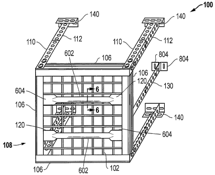
[1034] FIG. 1 shows a preferred suspended storage structure 100 including a
shelf or
deck 102 which can be, for example, a welded wire mesh, as shown, or a solid
sheet, such as
plywood, metal, or plastic. Deck 102 is supported by beams 106 that form a
rectangular
frame 108. A preferred embodiment uses four beams 106, two longitudinal beams
(a front
beam and a back beam) and two transverse side beams. Beams 106 are suspended
from
vertical supports, which preferably comprise a lower vertical corner support
110 and an upper
-5-
CA 02580788 2007-03-19
WO 2006/036998 PCT/US2005/034709
Attorney Docket No.: MB30 PCT
vertical corner support 112. Beams can be formed from steel or any other
appropriate material,
preferably with a thickness of at least 16 gauge. The vertical supports shown
in FIG. 1
comprise L-shaped supports mounted on each corner of deck 102. Preferably, the
vertical
supports are formed from steel or another appropriate material with a
thickness of at least 12
gauge or, more preferably, 10 gauge. Skilled persons will recognize that
vertical supports with
a different cross-section shape can be used, for example a flat or rectangular
cross-section.
Further, the vertical supports can be mounted at locations other than the
corners of deck 102 as
long as the deck is adequately supported.
[1035] FIG. 2 shows that upper and lower vertical corner supports 110 and 112
are
preferably L-shaped, with sides of approximately equal width. Each lower
vertical corner
support 110 has two keyhole shaped slots 202 toward the lower end on each of
the outer sides
of the vertical corner support 110. Deck 102 preferably does not extend past
frame 108,
thereby eliminating weaker cantilevered deck portions and facilitating the
side-by-side
placement of multiple storage structures 100. Vertical corner supports are
preferably, but not
always, constructed in two parts, such as upper part 112 and lower part 110,
so that a user can
adjust the height of the supports by overlapping different amounts of the
upper and lower parts.
The two parts can be connected using bolts, or other means, such as
interlocking slots on om
piece and protrusions on the other piece. For example, in one embodiment, the
length of the
combination of vertical corner supports 110 and 112 can be adjusted to be
between 20 inches
and 38 inches in 11/2-inch increments. The holes in upper part 112 have
appropriate shapes for
the connectors, for example, round holes if bolts are used, or key hole slots
for connecting to
protrusions in the mating members. The shape of the holes need not match the
shape of the
-6-
CA 02580788 2007-03-19
WO 2006/036998 PCT/US2005/034709
Attorney Docket No.: MB30 PCT
connectors exactly, for example oval holes could be used with bolts to allow
for more
adjustability.
[1036] FIG. 3 shows one preferred shape for beams 106. A preferred beam 106
comprises a 14-gauge steel, 21/2-inch wide, heavy-duty steel Z-shaped beam.
(The term "Z-
shaped" as used herein is not limited to beams having two horizontal and one
angled portion
between them like the letter "Z", but includes any beam having a cross section
with multiple
portions including an angled portion that is not substantially perpendicular
to a connected
portion.) The Z-shaped beams 106 include a horizontal portion 302 and a first
vertical portion
304 that extends upward from one end of the horizontal portion 302. As shown
in FIG. 3, deck
316 rests upon horizontal portion 302, while butting up against the bottom of
vertical portion
304. In some embodiments, the top of vertical portion 304 can extend above
deck 316. An
angled portion 306 extends from the end of horizontal portion 302 opposite to
that of vertical
portion 304 downwardly and toward the plane of vertical portion 302. Below
horizontal
surface 302 and above angled portion 306 is a space referred to as indentation
308. A second
vertical portion 310 extends from angled portion 306 downwardly in
approximately the same
plane of first vertical portion 302. In some embodiments in which storage
system 100 will
support extra weight, additional support can be provided by an addition
horizontal portion 312
that provides additional strength to beams 106. FIG. 3 shows a solid deck 316,
as an alternative
to the wire deck 102 of FIG. 1, supported on the top surface of the horizontal
portion 302 of
beam 106.
[1037] The invention is not limited to the beam configurations shown in FIG.
3. For
example, FIGS. 4A and 5A show alternative configurations, an L-shaped beam 402
and a C-
shaped beam 502, respectively, both used with a solid deck 316. When such
alternative
-7-
CA 02580788 2007-03-19
WO 2006/036998 PCT/US2005/034709
Attorney Docket No.: MB30 PCT
configurations are used, additional brackets (not shown) can optionally be
used to fix the
position of deck 102. FIGS. 4B and 5B show additional alternative
configurations, an L-
shaped beam 402 and a C-shaped beam 502, respectively, both used with a wire
deck 102.
[1038] At each end of each of the four beams 106 are connectors for coimecting
each
beam 106 to a mating connector on the corresponding vertical support 110. A
preferred
connector does not require an assembler to use a screwdriver or wrench to
connect threaded
fasteners, thereby facilitating assembly by "do-it-yourself' homeowners. In
one embodiment,
the connector consists of a post 320 (FIG. 3) and a round flat plate 322
positioned at the end of
post 320 and having a diameter larger than that of post 320. The plate is
inserted into the largo-
diameter portion of keyhole 202 (FIG. 2) of vertical corner support 110, and
then beain 106 is
moved downward until post 320 seats in the narrow end of keyhole slot 202. In
a preferred
embodiment, a rivet forms post 320 and flat plate 322. Other types of
connectors could be
used, and the keyhole could be positioned on beams 106, with the rivets on
vertical corner
connectors 110. In another embodiment, the connectors could be located on the
inner surface
of the beams so that the vertical supports are located inside the frame. If
necessary, deck
panels could be notched to accommodate the interior vertical supports.
[1039] One or more ribs 120 (FIG. 1) typically provide support for deck 102.
FIG. 6
shows a cross section, taken as shown by the lines 6- 6 of FIG. 1, of a
preferred rib 120 for use
with a wire deck 102. Rib 120 preferably comprise a V-shaped center portion
602 that
provides strength for supporting a load away from the frame 108 and flat end
portions 604 that
provide additional support for a wire deck 102 near frame 108. The opening of
the "V"
preferably faces the wire deck 102 to provide more contact area, and the top
of the"V" can be
flanged to provide a horizontal lip for even more contacting area. The V-shape
resists bending
-8-
CA 02580788 2007-03-19
WO 2006/036998 PCT/US2005/034709
Attorney Docket No.: MB30 PCT
along the span between opposing beams 106. Other cross-sectional shapes for
the ribs could be
used including U-shaped or square. The wires of wire deck 102 typically form a
grid pattern,
and flat end portions 604 preferably extend away from the frame beyond the end
of the first
row in the grid, thereby providing broad support for at least the first wire
that is away from the
frame 108 and that is transverse to the long axis of rib 120. The grid pattern
of wire deck 102
can include rectangles (including squares. i.e., rectangles having sides of
equal length),
diamonds, or other utilitarian or decorative patterns.
[1040] Preferably, at least some, and more preferably all, of the wires
forming wire
deck 102 are bonded to ribs 120, preferably by welding. Bonding the wire deck
102 to the ribs
creates a stronger, more rigid deck structure that can support a great deal of
weight without
sagging. Each of the wires crossing ribs 120 is preferably welded to the rib.
[1041] In various embodiments, decks 102 are 4 ft x 2 ft, 4 ft x4 ft, 6 ft x 2
ft, 6 ft x 4 ft,
8 ft x 2 ft and 8 ft x 4 ft, and can made in 3 ft x 2 ft or 4 ft x 2 ft
sections or deck panels, each
deck panel including 2 support ribs 120 to which the wires in the deck panel
are welded. In
some embodiments, decks 102 are 4 ft x 3 ft, 6 ft x 3 ft and 8 ft x 3 ft and
are made, for
example, in 4 ft x 3 ft or 3 ft x 2 ft deck panel, with each deck panel having
2 ribs. Referring
also to FIG. 15A and 15B, in one 2 ft by 8 ft embodiment shown in, the deck
102 is preferably
composed of two 2 ft by 4 ft welded wire deck panels 1503 and 1505, with two 4
ft support ribs
120 running under each panel. Wires from both panels are welded to the two
corresponding
support ribs. A 2 ft. cross support 121 runs between the two panels and
supports the ends of
ribs from each panel. The cross support preferably includes clips (not shown)
for attaching the
wires from both panels.
-9-
CA 02580788 2007-03-19
WO 2006/036998 PCT/US2005/034709
Attorney Docket No.: MB30 PCT
[1042] Beam 106 can optionally include multiple L-clips 702 as shown in FIG.
7. L-
clips 702 are positioned on beams 106 to maintain wire deck 102 in position. L-
clips 702 are
preferably attached by welding or by threaded fasteners. The vertical portion
of Irclips 702
preferably extends vertically to about the same height as the vertical portion
304 of beam 106
to prevent deck 102 from being displaced under load.
[1043] In embodiments that support a heavier load, additional support can be
provided
by center supports 130 (FIG. 1), which can be attached between the ceiling and
beams 106.
The term "center support" includes any supports positioned between the corner
supports 110
and is not limited to supports positioned half way between the corner supports
110. Center
supports 130 can preferably be positioned wherever desired along the length of
beams 106 to
provide additional support wllere the load is heaviest or to coincide with
building structure in
the ceiling, such as ceiling joists. In some embodiments, two center supports
are used, one
attached to the front beam 106 and one attached to the rear beam 106.
Additional center
supports can be added to accommodate a heavier load. In embodiments that
support heavier
loads, the beams and vertical supports (including center supports) can be
formed from thicker
gauge material. For example, vertical supports can be at least 10 gauge and
beams can be
greater than 14 gauge. As discussed above and shown in FIG. 3, additional
weight-bearing
support for the beams can also be provided by an addition horizontal portion
312 that provides
additional strength to beams 106.
[1044] FIG. 8 shows that a typical center support 130 includes a top vertical
portion 801 to which are attached one or two L-shaped brackets 804 for
attaching to a ce>7ing
joist or other structural component (not shown). Center support 130 also
includes a bottom
portion 802 attached to upper portion 801 using threaded fasteners or other
means such as
-10-
CA 02580788 2007-03-19
WO 2006/036998 PCT/US2005/034709
Attorney Docket No.: MB30 PCT
interlocking slots. Bottom portion 802 includes a bent portion 806 that fits
into the indention
308 in beam 106 to provide support to beam 106. Bent portion 806 preferably
extends into
indentation 308 until it touches or almost touches angled portion 306 of beam
106. A bolt 812
clamps vertical portion 304 of beam 106 between a square plate 810 and bottom
portion 802 of
center support 130 to secure center support 130 to beam 106. A spacer 814
fills the gap
between portion 802 and plate 810 near the bolt location. An Isclip 702 (FIG.
7) is preferably
positioned below bolt 812, and the bolt or an its associated hardware, such as
a lock-washer,
extends deck over a wire from- wire deck 102 to trap the wire between the -L-
clip and the bolt or
its hardware, thereby prevented wire deck 102 from coming off of its support
structure without
removal of the bolt.
[1045] Because the attachment of center support 130 to beam 106 does not
require a
hole in beam 106 at the point of attachment, center support 130 can be
attached anywhere along
the length of beam 106, and the position is not limited by the location of
holes in beam 106.
The position at which center support 130 is attached can be varied by the end
user depending
on the load distribution and on the position of ceiling structural members,
such as ceiling joists.
The center support is preferably positionable at any point along a continuous
portion of the
beams 106, meaning that the position along the beam is not limited by the
location of holes in
the beam, although there may still be specific points along the length of beam
106 at which the
center support cannot be positioned because of interfering structural
features. Also, because no
holes are necessary in beam 106, the beam is stronger and can support
additional weight
without requiring a larger, heavier beam.
[1046] Thus, the present invention provides great flexibility. For example, in
some
embodiments, if heavier items are loaded toward one end of deck 102,
additional center support
-11-
CA 02580788 2007-03-19
WO 2006/036998 PCT/US2005/034709
Attorney Docket No.: MB30 PCT
brackets 130 can be used to provide additional support. In some embodiments,
additional deck
ribs 120 can also be added in that area to shore up the deck. In other
embodiments, one or
more center supports can be used to replace some or all of the fixed vertical
supports discussed
above. Skilled persons will recognize that in these embodiments the
centersupports can be
mounted at the corners of the deck or at other positions as long as the deck
is adequately
supported.
[1047] The upper end of corner supports 112 (FIG. 1) are preferably attached
to L-
shaped ceiling brackets 140, which are attached to a building structure, such
as ceiling joists,
trusses, or beams, preferably wooden beams or metal joists. Brackets 140 are
typically bolted
onto the upper vertical corner support 112 , and the other arm of the Irshaped
bracket 140 is
then attached using screws or other fastening devices to a building structural
component. Slots
in the bracket 140 provide some adjustment for aligning the brackets with
building structural
components. Bracket 140 can be attached to either face of support 112, so that
bracket 140 can
be oriented parallel to the building structural component to facilitate
attaclunent. Ceiling
brackets 140 can be of any desired length, for example the brackets can be
long enough to span
and be mounted to several ceiling joists.
[1048] FIG. 9 shows that holes or brackets in the corner brackets 110 can be
used to
support a net 900 or other structure that keeps items on deck 102 from falling
off. FIG. 10
shows that a shade 1002 can be mounted on a ceiling 1004 or on brackets 110 of
storage
system 100. FIG. 9 shows the shade about three-quarters of the way down.
Multiple
shades 1002 can be pulled down to hide the contents of storage system 100.
Each shade 1002
includes a magnetic strip 1008 to hold the bottom of the shade in place
against beam 106.
Mechanical clips or hooks could also be used to keep the drawn shade in place.
-12-
CA 02580788 2007-03-19
WO 2006/036998 PCT/US2005/034709
Attorney Docket No.: MB30 PCT
[1049] Storage system can be made in various sizes, and the number of center
supports
130 and deck support ribs 120 can be varied with the overall size of the unit
and the weight to
be carried. Because deck 102 preferably does not extend past frame 108,
multiple storage units
100 can be positioned next to each other, with the frames juxtaposed. The
L,shaped vertical
corner supports facilitate bolting units together on any side. Combining units
incireases the
overall storage area by allowing an end user to create a loft composed of
several systems.
[1050] FIG. 11 shows a typical storage system 100 with items stored thereon.
Some
embodiments of the storage system, such as that shown in FIG. 12, are suitable-
for mounting
above the rails of a sliding overhead garage door, thereby making additional
storage space
available. While suitable for use in a residential garage, the invention is
not limited to such
use, and can be used wherever overhead storage is deJired.
[1051] FIG. 13 shows an alternative embodiment in which beams 106 can be
configured in two parts that slide into one another, to malce a system having
an adjustable
length and/or width. One beam 106 includes two slots 1302, one in the top
portion 304 and one
in the lower portion 310. The other beam includes near its end holes 1306 for
a connector that
can be secured with nuts or a threaded backing plate to keep the beam sections
together.
Suitable connectors can include, for example, bolts passing throughboth beams,
permanent
rivets at predeterinined locations or slidable rivets on the first beam.
Clamps such as those
shown in FIG. 14 below can also be used to hold the beams together. FIG. 14
shows an
alternative embodiment in which beams 106 can be configured in two parts that
slide into one
another, to make a system having an adjustable length and/or width. Two clamps
1402
including bolts 1404 hold the two beams 106 together. In some embodiments,
each clamp
-13-
CA 02580788 2007-03-19
WO 2006/036998 PCT/US2005/034709
Attorney Docket No.: MB30 PCT
1402 will include 2 bolts, one positioned near the top and one near the bottom
of each clamp, to
press against vertical surfaces 304 and 310, respectively.
[1052] Embodiments of the invention that use a Z-beam frame and a wire deck
welded
to support ribs provide a very stable, sturdy structure that is relatively
light weight, so that more
of the load bearing capacity of the building structural component is available
for useful load.
The adjustable center supports used in some embodiments spread the load on the
building
component, thereby increasing the maximum capacity. In many case, the
inventive system is
so strong that the maximuin load of an installed system is limited not by the
strength of the
system itself, but by the load bearing capacity of the building structural
components to which
the system is attached. For example, one embodiment of a four foot by eight
foot system that
uses 8 deck rib supports and four center beam supports, two along the front
beam and two
along the rear beam, can support 1000 pounds or more, although a lighter load
is recommended
if the structure is suspended from ceiling joists of a residential garage.
Some smaller
embodiments, such as those having a maximum dimension of four feet or less,
may not include
center supports. Embodiments that are six feet typically use two certer
supports. Whether or
not center supports are used in any embodiment will depend on the load to be
carried.
[1053] Table 1 below is a table that describes various embodiments.
Size (Feet) Approx Sliding No. of Wire Rib Deck Maximum Load
Weight Center Deck Panels Supports Capacity Residential
(Pounds) Supports (Quantity) (Structural)
(Quantity) (Size in (Pounds)
feet)
4x2 35 0 1(4x2) 2 400 (600)
4x3 45 0 1(4x3) 2 400 (600)
4x4 50 0 2(4x2) 4 500 (700)
6x2 60 2 2 (3x2) 4+1 center rib 600 (1000)
6x3 65 2 3(3x2) 6 600 (1000)
6x4 75 2 3(4x2) 6 600 (1000)
-14-
CA 02580788 2007-03-19
WO 2006/036998 PCT/US2005/034709
Attorney Docket No.: MB30 PCT
8x2 80 2 2 (4x2) 4+1 center rib 600 (1000)
8 x 3 85 2 4(3x2) 8 600 (1000)
8x4 90 2 4(4x2) 8 600 (1000)
Table 1
[1054] FIG. 15A shows another preferred embodiment of the present invention.
In
FIG. 15, suspended storage structure 1500 includes a rectangular shelf or deck
1502 formed by
positioning two substantially square deck panels 1503 and 1505 side by side.
The deck panels
can be, for example, a welded wire mesh, as shown, ora solid sheet, such as
plywood, metal, or
plastic. Deck 1502 is supported by transverse beams 1507 and longitudinal
beams 1506 that
form a rectangular frame 1508. Trarisverse beams 1507 do not extend lengthways
past the
lateral edges of deck 1502. Longitudinal beams 1506 extend to the outside
edges of transverse
beams so that transverse beams 1507 are butted up against the interior surface
of longitudinal
beams 1506. The corresponding lateral ends of transverse beams 1507 and
longitudinal beams
1506 can be attached, for example, by an L-shaped bracket 1509 welded or
otherwise attached
to the outside corner formed by the two beams. Transverse beams 1507 are
suspended from
vertical supports 1510. One or more ribs 120 provide support for each deck
panel. Cross
support 121 runs between the two panels and supports the ends of ribs from
each panel.
[1055] The vertical supports shown in FIG. 15A comprise supports mounted near
each
corner of deck 1502. The vertical supports do not have to be mounted directly
at thecorners of
the frame. Instead, the mounting position can be varied to allow, for example,
the location of
the vertical supports to match the location of ceiling joists, or to allow for
a larger opening
between supports so that larger objects can be stored on the shelf. In some
embodiments,
vertical supports can be flat bar steel (or other appropriate material) rather
than the ISshaped
steel supports discussed above in order to reduce manufacturing costs.
-15-
CA 02580788 2007-03-19
WO 2006/036998 PCT/US2005/034709
Attorney Docket No.: MB30 PCT
[1056] FIG. 15B shows another preferred embodiment of the present invention.
In FIG.
15B, deck panels 1503 and 1505 are positioned side by side and supported by
longitudinal
beams 1506 supporting both deck panels 1503 and by transverse beams 1507 each
supporting
only one panel. Longitudinal beams 1506 are suspended from vertical supports
1510. The
vertical supports shown in FIG. 15B comprise supports mounted near each end of
longitudinal
beams 1506.
[1057] All coiifigurations and dimensions described above are by way of
example only,
and the invention is not limited to any specific dimension or configuration of
the novel aspects.
Skilled persons will recognize that many brackets can be used on the ends of
beams and
support structures to facilitate connection, so when applicant states that one
part is connected to
another part, it is understood that the connection does not need to be
immediate and such
connection does not exclude the use of intermediary brackets.
[1058] While rectangular and square decks have been described, the invention
is not
limited to any particular shape of deck. As shown in Fig. 16, the invention
could be used for a
triangular storage system for mounting in a corner, the system including three
beams instead of
four, and the internal angles of some of the support brackets being less than
ninety degrees.
Fig. 16 shows a triangular storage system 1601 using three parallel support
ribs 120 oriented
perpendicular to the front edge of the triangular deck frame 1602. For
applications where less
support is needed, only one support rib can be used, preferably oriented
perpendicular to the
front edge 1610 of the triangular deck frame 1602 and running from the back
corner 1612 to
the front edge 1610.
[1059] As used herein, the term "L-shaped" does not exclude a shape in which
the two
sides of the "L" have equal length or a shape in which the angle of
intersection between the
-16-
CA 02580788 2007-03-19
WO 2006/036998 PCT/US2005/034709
Attorney Docket No.: MB30 PCT
arms varies from ninety degrees. Also, as used herein, the term "rectangle"
includes a square.
Further, as used herein the term "deck" can refer to a deck formed as one unit
or formed from
multiple smaller deck panels.
[1060] Although the present invention and its advantages have been described
in detail,
it should be understood that various changes, substitutions and alterations
can be made herein
without departing from the spirit and scope of the invention as defined by the
appended claims.
Moreover, the scope of the present application is not intended to be limited
to the particular
embodiments of the process, machine, manufacture, composition of matter,
means, methods
and steps described in the specification. As one of ordinary skill in the art
will readily
appreciate from the disclosure of the present invention, processes, machines,
manufacture,
compositions of matter, means, methods, or steps, presently existing or later
to be developed
that perform substantially the same function or achieve substantially the same
result as the
corresponding embodiments described herein may be utilized according to the
present
invention. Accordingly, the appended claims are intended to include within
their scope sudl
processes, machines, manufacture, compositions of matter, means, methods, or
steps.
[1061] We claim as follows:
-17-