Note: Descriptions are shown in the official language in which they were submitted.
CA 02581079 2007-03-14
WO 2006/039267 PCT/US2005/034584
MULTI-FUNCTIONAL ENDOSCOPIC SYSTEM FOR USE IN ELECTROSURGICAL
APPLICATIONS
FIBLD OF THE INVENTION
The present invention relates to medical devices, in general, and therapeutic
and
diagnostic endoscopes, in particular.
BACKGROUND OF THE INVENTION
As an aid to the early detection and treatment of disease, it has become well
established that there are major public healtli benefits that result from
regular endoscopic
examination and subsequent or simultaneous treatment of internal structures,
such as the
alimentary canals and airways, e.g., the esophagus, stomach, lungs, colon,
uterus, ureter,
kidney and other organ systems. A conventional imaging endoscope used for such
procedures is formed of a flexible tube that has a fiber optic light guide
that directs
illuminating light from an external light source to the distal tip, where it
exits the
endoscope and illuminates the tissue to be examined. Frequently, additional
optical
components are incorporated, in order to adjust the spread of light exiting
the fiber bundle
at the distal tip. An objective lens and fiber optic imaging light guide
communicating
with a camera at the proximal end of the endoscope or an imaging camera chip
installed
at the distal tip produces an image that is displayed to the examiner. In
addition, most
endoscopes include one or more working channels, through which medical
devices, such
as biopsy forceps, snares, fulguration probes, and other tools, may be passed.
Navigating the endoscope through complex and tortuous patlls in a way that
produces minimum pain, side effects, risk, or sedation to the patient is
critical to the
success of the examination. To this end, modern endoscopes include means for
deflecting the distal tip of the endoscope to follow the pathway of the
structure under
examination, with minimum deflection or friction force upon the surrounding
tissue. By
manipulating a set of control knobs, the examiner is able to steer the
endoscope during
insertion and direct it to a region of interest, in spite of the limitations
of such traditional
control systems, which may be clumsy, non-intuitive, and friction-limited.
In some endoscopic procedures, it is desirable to pass an electrosurgical
instrument through a working channel. The electrosurgical instruments are
typically
-1-
CA 02581079 2007-03-14
WO 2006/039267 PCT/US2005/034584
separate devices that are connected to a separate radio frequency (RF)
generator source,
i.e., electrosurgical generator, which is separate from the operator console
of the
endoscope. For example, a polypectomy snare is one such electrosurgical device
that is
used to perform a polypectomy procedure. A polypectomy procedure requires many
steps that include, for example, the user's navigating the endoscope shaft
through the
colon, identifying the polyp to be removed, selecting a polypectoiny snare of
appropriate
size, connecting the cable of the polypectomy snare to a separate
electrosurgical
generator, selecting the power level of the electrosurgical generator,
positioning an
activation foot pedal that is attached to the generator near the user, passing
the
polypectomy snare through the working channel, capturing the polyp in the
snare,
energizing the polypectomy snare with the foot pedal while viewing on a video
display of
the endoscope operator console, cutting off the polyp, de-energizing the
polypectomy
snare by removing pressure on the foot pedal, withdrawing the polypectomy
snare from
the working channel, and recovering the polyp througli the working channel,
either by
suction or via another instrument.
The above-described process is very labor- and time-intensive, and the cost of
the
separate electrosurgical instrumentation, in combination witli the endoscope
system, is
high and, thus, adds cost to the medical procedure. Many connections and
settings have
to be managed by the physician or assistant. For example, the physician cannot
watch the
video display of the endoscope operator console, while at the same time
adjusting the
settings of the electrosurgical generator, which is typically located behind
the physician.
Therefore, instructions are given to a nurse, for example, if the generator
settings need
adjustment. . Overall, the system setup may be disadvantageous, in that there
may be
many electrical cords required in order to interconnect all the
instrumentation that is
typically set up in a small space, which may contribute to a less-than-safe
worlcing
environment. Additionally, the foot pedal to.energize the electrosurgical
instrument is
often awkward for the physician to locate and use. Furthermore, because the
endoscope
and the electrosurgical generator do not have a common user interface, the
physician
must familiarize himself/herself with the user interface of the endoscope as
well as the
user interface of all the different electrosurgical devices.
To overcome these and other problems, there is a need for a low-cost imaging
endoscope and associated electrosurgical devices that can be used for a single
procedure
and thrown away. The endoscopic system should have improved simplicity and
ease of
-2-
CA 02581079 2007-03-14
WO 2006/039267 PCT/US2005/034584
use, a common user interface for the endoscope and associated electrosurgical
devices,
increased efficiency, greater clinical productivity and patient throughput,
improved safety,
and improved clinical advantages, by being able to do more than one task and,
thus, fewer
insertions, which has the result of requiring less medication and facilitating
faster
recovery for the patient. Additionally, it would be beneficial to provide an
endoscopic
system that has an improved data gathering and management system, i.e., fast
and
accurate electronic recording of all aspects of each procedure.
SUMMARY OF THE INVENTION
To achieve the above and other objects, in accordance with one embodiment of
the present invention, a multi-functional endoscopic system is provided for
use in
electrosurgical applications. The system includes generally four elements: an
imaging
endoscope, an operator console coupled with the imaging endoscope, at least
one
electrosurgical device coupled with the imaging endoscope, and an
electrical/electronic
support for the at least one electrosurgical device (e.g., an electrosurgical
generator and
associated controls), which is integrated into the operator console. Thus, the
electrical/electronic support for the at least one electrosurgical device is
integrally
provided in the operator console for the imaging endoscope, rather than
provided as a
separate device.
In accordance with another embodiment of the present invention, the imaging
endoscope and/or the at least one electrosurgical device are configured to be
disposable
after a single use.
In accordance with another embodiment of the present invention, the at least
one
electrosurgical device may be any one of a biopsy device, a snare device, a
Tomes cutter,
an injection device, a probe device, a needle knife device, a spatula device
(for wide area
ablation), a basket device, an ultrasonic device, an RF device, and an argon
plasma
ablation device.
In accordance with yet another embodiment of the present invention, the at
least
one electrosurgical device may include an optical memory or an RFID tag
containing its
type (e.g., ID) information, and the operator console may include means for
reading the
type information so as to retrieve settings corresponding to the identified
electrosurgical
device as stored in the operator console memory.
In accordance with a further embodiment of the present invention, the imaging
endoscope and the at least one electrosurgical device are integrally formed.
-3-
CA 02581079 2007-03-14
WO 2006/039267 PCT/US2005/034584
In accordance witli still another embodiment of the present invention, the
imaging
endoscope includes at least one working channel through which the at least one
electrosurgical device is inserted.
In accordance with another embodiment of the present invention, the multi-
functional endoscopic system further includes a video display coupled to the
operator
console. The video display is configured to provide a graphical representation
that is
specific to the at least one electrosurgical device, after the operator
console determines
the type of the at least one electrosurgical device.
In accordance with another embodiment of the present invention, the imaging
endoscope includes a handheld controller, which is coupled to the operator
console. The
handheld controller is configured to control the operation of not only the
imaging
endoscope but also the at least one electrosurgical device. In a further
aspect of the
present invention, the at least one electrosurgical device is coupled to the
imaging
endoscope at the handheld controller. In a still f-urther aspect of the
present invention, the
handheld controller is configured to permit a user to selectively activate the
electrical/electronic support for the at least one electrosurgical device.
In accordance with yet another embodiment of the present invention, a multi-
functional endoscopic system is provided for use in surgical applications,
which includes
generally four elements: an imaging endoscope, an operator console coupled
with the
imaging endoscope, a handheld controller coupled with the operator console,
and at least
one surgical device coupled with the handheld controller. The handheld
controller is
configured to control the operation of not only the imaging endoscope but also
the at least
one surgical device.
In accordance with another embodiment of the present invention, a multi-
functional endoscopic system for use in surgical applications is provided. The
system
includes: an imaging endoscope; a handheld controller coupled to the imaging
endoscope;
and at least one surgical device integrally formed with the imaging endoscope.
The at
least one surgical device is coupled to the handheld controller. The handheld
controller is
configured to control the operation of the imaging endoscope and the at least
one surgical
device.
In accordance with a further embodiment of the present invention, an operator
console for an imaging endoscope is provided. The console integrally includes
an
electrical/electronic support for at least one electrosurgical device. In one
embodiment,
-4-
CA 02581079 2007-03-14
WO 2006/039267 PCT/US2005/034584
the electrical/electronic support is an electrosurgical generator for the at
least one
electrosurgical device.
In accordance with yet another embodiment of the present invention, a multi-
functional electrosurgical system is provided. The system includes at least
one
electrosurgical device, and an operator console having an
electrical/electronic support for
the at least one electrosurgical device. Each of the at least one
electrosurgical device
includes a smart device, such as an RFID tag, containing information directed
to a type
and perhaps also working parameters of the electrical device. The operator
console is
configured to determine the type (and perhaps also the working paraineters) of
the at least
one electrosurgical device based on the smart card so as to operate the
electrical/electronic support based on the determination.
BRIEF DESCRIPTION OF THE DRAWINGS
The foregoing aspects and many of the attendant advantages of this invention
will
become more readily appreciated as the same become better understood by
reference to
the following detailed description, when taken in conjunction with the
accompanying
drawings, wlierein:
FIGURE 1 illustrates a functional block diagram of a multi-functional
endoscopic
system for use in electrosurgical applications in accordance with an
embodiment of the
invention.
FIGURE 2 illustrates a perspective view of an imaging endoscope in accordance
with a first embodiment of the invention.
FIGURE 3 illustrates a perspective view of a handlield manual controller of an
imaging endoscope in accordance with an embodiment of the present invention.
FIGURE 4 illustrates a perspective view of an electrosurgical device in
accordance with an embodiment of the invention.
FIGURE 5 illustrates a perspective view of a multi-functional endoscopic
system
in accordance with an embodiment of the present invention.
FIGURE 6 illustrates a flow diagram of an example method of using a multi-
functional endoscopic system in accordance with an embodiment of the present
invention
in a polypectomy procedure.
FIGURE 7 illustrates a perspective view of an integrated imaging endoscope in
accordance with an embodiment of the invention.
-5-
CA 02581079 2007-03-14
WO 2006/039267 PCT/US2005/034584
FIGURE 8 illustrates a perspective view of an example integrated imaging
endoscope, into which a spatula device is integrated in accordance with an
embodiment
of the invention.
FIGURE 9 illustrates a perspective view of another example of an integrated
imaging endoscope, into which both a spatula and a needle-knife device are
integrated in
accordance with an embodiment of the invention.
FIGURE 10 illustrates a perspective view of yet another example of an
integrated
imaging endoscope, into which a snare is integrated in accordance with an
einbodiment of
the invention.
FIGURE 11 illustrates a perspective view of yet another example of an
integrated
imaging endoscope, into which forceps are integrated in accordance with an
embodiment
of the invention.
DETAILED DESCRIPTION OF THE PREFERRED EMBODIMENT
The present invention is a multi-functional endoscopic system for use in
electrosurgical applications. The multi-functional endoscopic system includes
an
imaging endoscope that may be used in conlbination with various
electrosurgical devices,
all of wliich are sufficiently inexpensive to manufacture, such that the
endoscope and
electrosurgical devices are considered single use, disposable items. The multi-
functional
endoscopic system of the present invention is suitable for use with a variety
of common
electrosurgical devices that are used, typically, in combination with an
imaging
endoscope and that require electrical/electronic support to function. The
electrical/electronic support for these electrosurgical devices (e.g., an
electrosurgical
generator and associated controls) may be integrated into an operator console
of the
imaging endoscope of the multi-functional endoscopic system of the present
invention,
rather than provided as a separate device, as is the case in typical
endoscopic systems. In
another embodiment of the invention, an integrated imaging endoscope is
provided that
integrates, into one apparatus, the functions of both an imaging endoscope and
an
electrosurgical device. The integrated imaging endoscope is sufficiently
inexpensive to
manufactu're, such that it is considered a single use, disposable item.
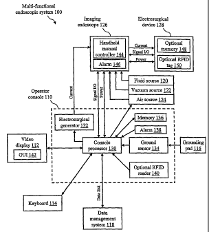
FIGURE 1 illustrates a functional block diagram of an exemplary
multifunctional
endoscopic system 100 for use in electrosurgical applications in accordance
with one
embodiment of the invention. Multifunctional endoscopic system 100 includes an
operator console 110 that is electrically connected to a video display 112, a
keyboard 114,
-6-
CA 02581079 2007-03-14
WO 2006/039267 PCT/US2005/034584
a grounding pad 116, and a data management system 118. Multi-functional
endoscopic
system 100 further includes a fluid source 120, a vacuum source 122, an air
source 124,
and a single-use imaging endoscope 126 that are all electrically,
mechanically, and fluidly
connected to operator console 110, and an electrosurgical device 128 that is
electrically,
mechanically, and fluidly connected to imaging endoscope 126.
Operator console 110 fiuther includes a console processor 130, an
electrosurgical
generator 132, a ground sensor 134, a memory 136, an alarm 138, and an
optional radio
frequency identification (RFID) reader 140. Video display 112 further includes
a
graphical user interface (GUI) 142, wliich may include a touch screen for
receiving user
input. Imaging endoscope 126 further includes a handheld manual controller 144
and an
alarm 146. Electrosurgical device 128 further includes an optional memory 148
and an
optional RFID tag 150. Additional details of operator console 110, imaging
endoscope 126, electrosurgical device 128, and handheld manual controller 144
are found
in reference to FIGURES 2 througli 6.
Operator console 110 is described generally as a special-purpose electronic
and
electromechanical apparatus that facilitates, processes, and manages all
functions of
multi-functional endoscopic system 100 via console processor 130, which is
representative of a standard microprocessor device, such as a Philips 8051 8-
bit
microcontroller or a Motorola 6816 16-bit microcontroller. Console processor
130 is
loaded with software for managing, for example, the operation of imaging
endoscope 126
and its associated imaging electronics (not shown) to create and/or transfer
images
received from an image sensor within imaging endoscope 126 to video display
112 for
viewing by a user, the operation of electrosurgical device 128, the operation
of
electrosurgical generator 132, and data transfer to and from data management
system 118.
Additionally, operator console 110 includes a physical connection to imaging
endoscope 126, a network connection to remote data management system 118, and
connections to fluid source 120, vacuum source 122, and air source 124, which
are
representative of sources of air, vacuum, insufflation gas, and/or fluids.
Fluids include,
for example, irrigation liquids, medication, and dyes for marking tissue.
Video display 112 and keyboard 114 are standard I/O devices used with
computers and the like.. Video display 112 is any special-purpose or
conventional
computer display device, such as a computer monitor or flat panel display,
which outputs
graphical images to a user, for example, via GUI 142, which provides a system-
or
-7-
CA 02581079 2007-03-14
WO 2006/039267 PCT/US2005/034584
instrument-specific graphical representation of the varioiis fiuictions of
multi-functional
endoscopic system 100. Additionally, GUI 142 of video display 112 may be
configured
to include a touch screen for receiving user input.
Electrosurgical generator 132 is representative of a commercially available or
custom designed device used in electrosurgery, wherein radiofrequency energy
is used to
produce cutting and/or coagulation in body tissues. More specifically,
electrosurgical
generator 132 is a machine that coverts low-frequency alternating current to
high-
frequency electrosurgical current, i.e., radiofrequency energy.
Electrosurgical
generator 132 is capable of providing higll-frequency electrosurgical current
to
electrosurgical device 128. Electrosurgical generator 132 is integrated
physically into the
apparatus of operator console 110, rather than provided as a separate device,
as is the case
in typical endoscopic systems.
Ground sensor 134 is used to sense whether grounding pad 116 is properly
attached to the patient. Grounding pad 116 and ground sensor 134 are required
in the
case in which electrosurgical device 128 is a monopolar device and are not
used in the
case in which electrosurgical device 128 is a bipolar device. A monopolar
electrosurgical
device is one wherein the active electrode of the device requires the use of a
dispersive
pad, i.e., grounding pad 116, to complete the circuit. By contrast, a bipolar
electrosurgical device is one wherein the device has both active and return
electrodes in
one handpiece. Monopolar vs. bipolar instrutnentation is procedure dependant.
Memory 136 is any commercially available non-volatile, writable/readable
computer memory device, such as any standard FLASH memory device. The
write/read
operations of memory 136 are controlled via console processor 130. Memory 136
serves
as local storage for information that, subsequently, may be transferred
to/from data
management system 118 or displayed to the user. Types of information that are
stored in
memory 136 are, for example, user information, user preferences, type of and
default
settings of attached electrosurgical device, and electrosurgical generator 132
settings,
such as the energy level and duration of the current. The information stored
in
memory 136 may be transmitted to data management system 118 and used, for
example,
for performing any desired tracking operations or for generating procedure
reports. Data
management system 118 is representative of a centralized repository that is
networked by
any standard wired or wireless data linlc to one or more multi-functional
endosc6pic
systems 100.
-8-
CA 02581079 2007-03-14
WO 2006/039267 PCT/US2005/034584
Alarm 138 of operator console 110 and alarm 146 of imaging endoscope 126 are
representative of any standard, audible and/or visible alarm mechanism, such
as an audio
spealcer and/or a light source.. Conditions that may trigger alarm 138 and
alarm 146 are,
for example, ground sensor 134 sensing that grounding pad 116 is not properly
attached
to the patient or the electrical or mechanical connections to fluid source
120, vacuum
source 122, air source 124, imaging endoscope 126, or electrosurgical device
128 being
not properly connected. A visual alarm indication may also be provided by GUI
142 via
video display 112.
Imaging endoscope 126 is an instrument that allows for the examination of the
interior of a canal or hollow organ of a patient. Imaging endoscope 126
further includes
an illumination mechanism (not shown), an image sensor (not shown), and an
elongate
shaft (not shown) that has one or more lumens located therein. Imaging
endoscope 126
may be designed to be sufficiently inexpensive to manufacture, such that it
may be
considered a single use, disposable item, such as is described in reference to
U.S. Patent
Application Nos. 10/811,781, filed March 29, 2004, 10/406,149, filed April 1,
2003, and
10/956,007, filed September 30, 2004, assigned to Scimed Life Systems, Inc.,
now
Boston Scientific Scimed, Inc. and which are incorporated herein by reference.
The
'007 patent application describes an endoscope imaging system that includes a
reusable
control cabinet with a number of actuators, or a manual control on the
endoscope, that
controls the orientation of a lightweight endoscope. The endoscope may be used
with a
single patient and then disposed. The endoscope includes an illumination
mechanism, an
image sensor, and an elongate shaft that has one or more lumens located
therein. An
articulation joint at the distal end of the endoscope allows the distal end to
be oriented by
the actuators in the control cabinet. Further details of imaging endoscope 126
are found
in reference to FIGURES 2 through 6.
Handheld manual controller 144 of imaging endoscope 126 is a handheld device
that is electrically and mechanically connected to operator console 110.
Handheld
manual controller 144 accepts inputs from a human operator via standard push
buttons,
rotary knobs, joysticks, or other activation devices either singularly or in
combination to
control the operation of imaging endoscope 126 and electrosurgical device 128.
Handheld manual controller 144 of imaging endoscope 126 provides a direct
electrical
connection port for connecting electrosurgical device 128 to operator console
110 and,
-9-
CA 02581079 2007-03-14
WO 2006/039267 PCT/US2005/034584
subsequently, to electrosurgical generator 132. Further details of handheld
manual
controller 144 are found in reference to FIGURES 2 through 6.
Electrosurgical device 128 is representative of a variety of common or to-be-
developed electrosurgical medical devices used in combination with an
endoscope, for
example but not limited to, a biopsy device, a snare device, a Tomes cutter,
an injection
device, a probe device, a needle knife device, a spatula device (for wide area
ablation), a
basket device, an ultrasonic device, an RF device, and an argon plasma
ablation device
(which would require an argon source). These devices require
electrical/electronic
support in order to function in endoscopes. The electrical/electronic support
for
electrosurgical device 128 (i.e., electrosurgical generator 132 and associated
controls) is
integrated into operator console 110 of multi-functional endoscopic system
100, rather
than provided as a separate device, as is the case in typical endoscopic
systems. Either
optional memory 148 or optional RFID tag 150 may be installed in
electrosurgical
device 128 as a means to provide device information, such as device type
identification
and the associated default operation settings. In the case of optional memory
148, which
is, for example, any commercially available, non-volatile read-only memory
(ROM), this
information is transmitted directly to and processed by console processor 130.
In the case
of optional RFID tag 150, a user must swipe electrosurgical device 128 in
close proximity
to optional RFID reader 140 of operator console 110 and, thus, the information
is
extracted and then processed by console processor 130. Like imaging endoscope
126,
electrosurgical device 128 is sufficiently inexpensive to manufacture, such
that it is
considered a single use, disposable item. Further details of electrosurgical
device 128 are
found in reference to FIGURES 4 through 6.
Optional RFID reader 140 of operator console 110 is used in combination with
optional RFID tag 150 of electrosurgical device 128. Optional RFID tag 150 is
a well-
known electronic product code (EPC) device that provides a unique, factory-
prograinmed
identification code. Optional RFID tag 150 is, for example, a low frequency,
battery-free
transponder device that is read via radio waves. An example of optional RFID
tag 150 is
an RFID tag manufactured by Texas Instruments Inc (Dallas, TX). Typically, up
to
96 bits of information are stored upon an RFID tag. These 96 bits provide
product
information, such as product name, product manufacturer, and a 40-bit serial
number.
Optional RFID tag 150 may be a read-only device or a read/write device that
can be
programmed. The factory-programmed identification code (e.g., EPC) upon
optional
-10-
CA 02581079 2007-03-14
WO 2006/039267 PCT/US2005/034584
RFID tag 150 may be extracted via optional RFID reader 140, which is located
within
operator console 110. Optional RFID reader 140 is an electronic device formed
of an RF
transmitter and receiver and an antenna to communicate with RFID transponders,
such as
optional RFID tag 150. Optional RFID reader 140 is a device that scans
optional RFID
tag 150 via radio waves and passes the information in digital form to memory
136 or data
management system 118 via console processor 130. Example manufacturers of RFID
readers include Antenova Ltd. (Cambridge, England) and Bancolini (Bologna,
Italy).
FIGURE 2 illustrates a perspective view of imaging endoscope 126 in accordance
with a first embodiment of the invention. FIGURE 2 shows that imaging
endoscope 126
includes an endoscope proximal shaft 210 that is electrically, mechanically,
and fluidly
connected, at one end, to an endoscope proximal connector 212 and, at an
opposite end,
to a port of handheld manual controller 144. Imaging endoscope 126 further
includes an
endoscope distal shaft 214 that is electrically, mechanically, and fluidly
connected, at one
end, to a port of handheld manual controller 144, which is further detailed in
reference to
FIGURE 3, and has an endoscope distal tip 216 located as its opposite end for
advancing
into a patient's body.
The housing of endoscope proximal connector 212 is formed of a suitably
lightweight, rigid material, such as molded plastic. Endoscope proximal
connector 212
provides a quick-release mechanism for making and breaking all electrical,
mechanical,
and fluid/air/vacuum connections. The quick-release inecha.nism allows
endoscope
proximal connector 212 to be easily secured to the exterior of operator
console 110.
Endoscope proximal connector 212 includes wires and tubes (not shown) that
pass
through endoscope proximal shaft 210, then through handlield manual controller
144,
then through endoscope distal shaft 214 and then to endoscope distal tip 216.
Endoscope proximal shaft 210 and endoscope distal shaft 214 are formed of a
suitably lightweight, flexible material, such as polyurethane. Endoscope
proximal
shaft 210 and endoscope distal shaft 214 are elongated shafts that have one or
more
lumens located therein and wiring located therein to support, for example, a
working
channel, a bolus wash, jet wash, or lens wash mechanism, and an illumination
mechanism
and an image sensor that are located at endoscope distal tip 216. Also
included within
handheld manual controller 144 and endoscope distal shaft 214 are the
electrical and
mechanical mechanisms for articulating endoscope distal tip 216 for advancing
into a
patient.
-11-
CA 02581079 2007-03-14
WO 2006/039267 PCT/US2005/034584
FIGURE 3 illustrates a perspective view of handheld manual controller 144 in
accordance with an embodiment of the invention. FIGURE 3 shows that handheld
manual controller 144 includes a controller housing 310 formed of a suitably
lightweight,
rigid material, such as molded plastic. Controller housing 310 is
electrically,
mechanically, and fluidly connected, at one end, to endoscope proximal shaft
210 and, at
an opposite end, to endoscope distal shaft 214. Mounted within controller
housing 310 of
handheld manual controller 144 is a plurality of control buttons 312 that
allow the
physician to manipulate the functions of the endoscope, such as taking a
picture,
activating light, activating water, activating air, or activating suction at
endoscope distal
tip 216; a plurality of rotary knobs 314 for controlling the articulation of
endoscope distal
tip 216 for advancing into the patient; a working channel access port 316 that
allows the
insertion of any therapeutic or diagnostic instruments into the working
channel of
endoscope distal shaft 214; an endoscope electrical connector 318 that
provides a
conveniently located electrical connection mechanism for connecting signal I/O
and
power of electrosurgical device 128 to operator console 110; and a medical
device
activation,button 320 for activating electrosurgical generator 132 wllich
supplies current
to electrosurgical device 128. Additionally, mounted within controller housing
310 of
handheld manual controller 144 is alarm 146, as described in more detail in
reference to
FIGURE 1.
Medical device activation button 320 is a conveniently located mechanism for
activating electrosurgical generator 132. Medical device activation button 320
replaces,
for example, a separate foot pedal device, which, typically, is not
conveniently located
and may be cumbersome to operate in conjunction with typical endoscopic
systems.
Handheld manual controller 144 is a handheld controller that accepts inputs
from
a human operator via standard control buttons 312, rotary knobs 314, medical
device
activation button 320 or other activation devices, either singularly or in
combination, in
order to control the operation of imaging endoscope 126 and electrosurgical
device 128.
Handheld manual controller 144 may optionally provide a ground connection port
(not
shown) for connecting grounding pad 116. Alternatively or additionally to
rotary knobs
314 (and control buttons 312 and medical device activation button 320),
handheld manual
controller 144 may include a multi-positional switch, or a joy-stick type
switch, to control
the orientation or articulation of endoscope distal tip 216 or to activate
various functions
of the endoscope or the electrosurgical medical device. Some exemplary
embodiments of
-12-
CA 02581079 2007-03-14
WO 2006/039267 PCT/US2005/034584
a multi-positional switch suitable for use in the present invention are
disclosed in the '007
patent application, incorporated herein by reference above. In one embodiment,
such a
multi-positional switch may be further configured and used to change
operational settings
for electrosurgical device 128, such as the energy level and time duration
setting of
electrosurgical generator 132.
FIGURE 4 illustrates a perspective view of electrosurgical device 128 in
accordance with an embodiment of the invention. Electrosurgical device 128 is
representative of a typical electrosurgical medical device for inserting into
the working
channel of a.n endoscope. Example electrosurgical medical devices include, but
are not
limited to, a biopsy device, a snare device, a Tomes cutter, or an injection
or probe device
or other types of ultrasonic, or RF devices.
FIGURE 4 shows that electrosurgical device 128 includes a body 410, a working
channel adaptor 412 that is tapered, such that it is easily mated to working
channel access
port 316 of handheld manual controller 144, a device shaft 414 that has a
device distal
tip 416, and an actuator handle 418. Actuator handle 418 is mounted within
body 410
and is used to actuate the specific instrument extending along device shaft
414 and out of
device distal tip 416. Also mounted within or on body 410 may be optional
memory 148
or optional RFID tag 150, as described in more detail in reference to FIGURE
1. Finally,
electrosurgical device 128 includes a device cable 420, that is electrically
and
mechanically connected, at one end, to body 410 and, at the opposite end, to a
device
electrical connector 422. Electrosurgical device 128 is sufficiently
inexpensive to
manufacture, such that it is considered a single use, disposable item.
Device electrical connector 422, at the end of device cable 420, is any
standard
connector that provides a convenient electrical comiection mechanism for
connecting
signal I/O and power of electrosurgical device 128 to endoscope electrical
connector 318
of handheld manual controller 144 and, subsequently, to operator console 110.
The
length of device cable 420 is allowed to be as suitably short as is practical,
because
endoscope electrical connector 318 of handheld manual controller 144, into
which device
electrical connector 422 is connected, is located in close proximity to
electrosurgical
device 128, when it is installed in imaging endoscope 126, as shown in more
detail in
reference to FIGURE 5. The length of device cable 420 is suitably short, as
compared
with a typical cable needed to connect a standard electrosurgical device to a
separate
electrosurgical generator console, as is the case in typical endoscopic
systems. As a
-13-
CA 02581079 2007-03-14
WO 2006/039267 PCT/US2005/034584
result, cable 420, which is short in length, replaces the long, cumbersome
cable of
conventional devices.
FIGURE 5 illustrates a perspective view of an exemplary multi-functional
endoscopic system 100 in accordance with the invention. More specifically,
FIGURE 5
shows imaging endoscope 126 and electrosurgical device 128, which are both
disposable
elements, in use with operator console 110. Imaging endoscope 126 is
electrically and
mechanically connected to the side of operator console 110 via endoscope
proximal
connector 212. Endoscope proximal connector 212 is for example, fluidly
connected to
fluid source 120 via tubing. In like manner, endoscope proximal connector 212
may be
connected to vacuuin source 122 (not shown) or air source 124 (not shown).
Electrosurgical device 128 is electrically and mechanically connected to
imaging
endoscope 126 via device electrical comiector 422 (not shown) at the end of
device
cable 420, which plugs into endoscope electrical connector 318 (not shown) of
handheld
manual controller 144. The electrical/electronic connections for both imaging
endoscope 126 and electrosurgical device 128 are facilitated via handheld
manual
controller 144 and passed onto the supporting electronics, such as
electrosurgical
generator 132, within operator console 110 via endoscope proximal shaft 210
(not shown)
and endoscope proximal connector 212.
Additionally, FIGURE 5 shows device shaft 414 of electrosurgical device 128
inserted into working channel access port 316 of handheld manual controller
144, which
thereby allows device shaft 414 to pass along the length of the working
channel of
endoscope proximal shaft 214, such that device distal tip 416 (not shown) may
extend out
of endoscope distal tip 216.
With reference to FIGURES 1 through 5, an exemplary operation of inulti-
functional endoscopic system 100 is described as follows. A user, which may be
a
physician, nurse, or other assistant, attaches imaging endoscope 126 to the
side of
operator console 110 via endoscope proximal connector 212 and activates
operator
console 110. User information may be captured and stored in memory 136 via,
for
example, manual entry by means of keyboard 114 or downloaded from data
management
system 118. The user verifies that all required fluid, gas, air, or vacuum
sources, such as
fluid source 120, vacuum source 122, air source 124 or the lilce, are
available. The
physician introduces endoscope distal tip 216 into the patient and advances it
by using
rotary knobs 314 of handheld manual controller 144, until such time that the
target site
-14-
CA 02581079 2007-03-14
WO 2006/039267 PCT/US2005/034584
may be visualized upon video display 112. The appropriate type of
electrosurgical
device 128 is selected, depending on the medical procedure being performed.
Device
shaft 414 of electrosurgical device 128 is inserted into working channel
access port 316
of handheld manual controller 144 and advanced, until such time that device
distal
tip 416 extends from endoscope distal tip 216 and is visualized upon video
display 112.
If electrosurgical device 128 is a monopolar device, grounding pad 116 is
placed upon the
patient. Device electrical connector 422 of electrosurgical device 128 is
connected to
endoscope electrical connector 318 on handheld manual controller 144. If
optional
memory 148 is present in electrosurgical device 128, console processor reads
the device
information and stores it in memory 136 of operator console 110. Otherwise,
optional
RFID tag 150 of electrosurgical device 128 may be manually scanned by optional
RFID
reader 140 of operator console 110, in order to obtain device information.
Using the
device information stored in memory 136, the default settings of the
particular
electrosurgical device 128 are displayed to the user via GUI 142, and the user
may elect
to adjust these settings. The medical procedure is then performed by the
physician
manipulating control buttons 312 and rotary knobs 314 of handheld manual
controller 144, in order to manage the functions of imaging endoscope 126; by
a nurse or
assistant manipulating actuator handle 418 of electrosurgical device 128 to
manipulate
the actuator of electrosurgical device 128; and by the physician manipulating
medical
device activation button 320 of handheld manual controller 144 to activate
current from
electrosurgical generator 132 that drives the active element of
electrosurgical device 128.
After the medical procedure is completed, electrosurgical device 128 is
withdrawn from
imaging endoscope 126, imaging endoscope 126 is withdrawn from the patient,
and
endoscope proximal connector 212 of imaging endoscope 126 is disconnected from
the
side of operator console 110 via its quick-release mechanism. Imaging
endoscope 126
and electrosurgical device 128 are properly disposed of.
Throughout the medical procedure, data is being logged in memory 136 under the
control of software loaded in console processor 130. After the medical
procedure is
completed, the user may initiate a data transfer operation to transmit the
procedure data
from operator console 110 to data management system 118 for further
processing. An
example detailed method of using multi-functional endoscopic system 100 is
described in
more detail in reference to FIGURE 6.
-15-
CA 02581079 2007-03-14
WO 2006/039267 PCT/US2005/034584
FIGURE 6 illustrates a flow diagram of an example method 600 of using multi-
functional endoscopic system 100 in a polypectomy procedure in accordance with
asi
embodiment of the invention. Method 600 and multi-functional endoscopic system
100
are not liinited to a polypectomy procedure. Those skilled in the art will
recognize that
the method steps of method 600 may be adapted easily to apply to any of the
various
medical procedures that use the various types of electrosurgical devices,
respectively.
Method 600 includes the steps of:
Step 610: Connecting endoscope and activating operator console
In this step, a user, which may be a physician, nurse, or other assistant,
attaches
endoscope proximal connector 212 of imaging endoscope 126 to the side of
operator
console 110 and activates operator console 110. Method 600 proceeds to step
612.
Step 612: Capturing user infof n2ation
In this step, user information, such as the user's name, is captured and
stored in
memory 136 via, for example, manual entry upon keyboard 114 or downloaded from
data
management system 118. Method 600 proceeds to step 614.
Step 614: Intubating the patient
In this step, the physician intubates the patient, by introducing and
advancing
endoscope distal tip 216 of imaging endoscope 126 into a body cavity of the
patient.
Method 600 proceeds to step 616.
Step 616: Achieving visualization ofpolyp to be removed
In this step, the physician advances endoscope distal tip 216 of imaging
endoscope 126 into the patient, by using control buttons 312 and rotary knobs
314 of
handheld manual controller 144, until such time that the polyp to be removed
is
visualized at endoscope distal tip 216 and the image is displayed to the user
upon video
display 112. Method 600 proceeds to step 618.
Step 618: Selecting appropriate polypectomy snare
In this step, the physician selects the appropriate type of electrosurgical
device 128. In this example, an electrosurgical device 128 that includes a
polypectomy
snare of the desired size is selected, based upon the size of the polyp to be
removed.
Method 600 proceeds to step 620.
Step 620: Preparing the polypectomy snaf e
In this step, the user unwraps the selected electrosurgical device 128 from
its
packaging and, by opening and closing electrosurgical device 128 by using
actuator
-16-
CA 02581079 2007-03-14
WO 2006/039267 PCT/US2005/034584
handle 418, verifies that electrosurgical device 128 is operational. Method
600 proceeds
to step 622.
Step 622: Introducing polypectorny snare into endoscope and achieving
visualization tlzereof
In this step, the user inserts device shaft 414 of electrosurgical device 128
into
working channel access port 316 of handheld manual controller 144 and advances
device
shaft 414, until such time that device distal tip 416 is fully captured in the
field of view,
while extended 5 - 10 mm from endoscope distal tip 216. The image is displayed
to the
user upon video display 112. Method 600 proceeds to step 624.
Step 624: Connecting grounding pad
In this step, because electrosurgical device 128 is a monopolar device, the
user
places grounding pad 116 upon the patient and connects grounding pad 116 to
operator
console 110 or, alternatively, to a ground port on handlield manual controller
144.
Method 600 proceeds to step 626.
Step 626: Connecting electrosurgical device cable to manual controller
In this step, the user connects electrosurgical device 128 to imaging
endoscope 126, by plugging device electrical connector 422 of electrosurgical
device 128
into endoscope electrical comiector 318 on handheld manual controller 144 and
thereby
achieving an electrical comiection to the electrical/electronic support
electronics, e.g.,
electrosurgical generator 132, within operator console 110. Furthennore,
handheld
manual controller 144 and operator console 110 are the user interface for
electrosurgical
device 128. Metllod 600 proceeds to step 628.
Step 628: Capturing electrosurgical device information
In this step, if optional memory 148 is present in electrosurgical device 128,
console processor 130 reads the device information, such as the device type
and its
default settings, from optional memory 148 of electrosurgical device 128 and
stores it in
memory 136 of operator console 110. Otherwise, optional RFID tag 150 of
electrosurgical device 128 may be scanned manually by optional RFID reader 140
of
operator console 110, in order to obtain device information. Method 600
proceeds to
step 630.
Step 630: Displaying and selecting polypectorny snaf e settings
In this step, under the control of console processor 130, the default settings
and/or
physician-specific settings of electrosurgical device 128 are displayed to the
user via
-17-
CA 02581079 2007-03-14
WO 2006/039267 PCT/US2005/034584
GUI 142. The physician-specific preferences are available to the console via a
connection to the centralized data management system 118. Subsequently, the
user may
elect to use the default settings, the physician-specific settings, or to
adjust the settings.
The adjustment of settings may be perfonned by using any type of user input
device, such
as a touch screen provided as part of GUI 142 of video display 112, keyboard
114, or by
using a multi-positional switch (i.e., joy-stick type switch), as described
above. Settings
include, for example, the energy level and time duration setting of
electrosurgical
generator 132. Method 600 proceeds to step 632.
Step 632: Storing device settings
In this step, under the control of console processor 130, the selected device
settings of electrosurgical device 128 are stored in memory 136 in console
processor 130.
Method 600 proceeds to step 634.
Step 634: Articulating endoscope tip to polyp site
In this step, the physician articulates endoscope distal tip 216 into the
patient and
advances it to the polyp to be removed, by manipulating control buttons 312
and rotary
knobs 314 of handheld manual controller 144, which manage the functions of
imaging
endoscope 126. Method 600 proceeds to step 636.
Step 636: Captuf ing polyp in polypectonzy snare
In this step, while the physician maintains the angulation to the polyp to be
removed, a nurse or assistant opens and closes the polypectomy snare of
electrosurgical
device 128, by using actuator handle 418, and thereby grasps the polyp to be
removed.
Method 600 proceeds to step 638.
Step 638: Cutting the polyp with polypectomy snare
In this step, the physician presses medical device activation button 320 of
handheld manual controller 144 to adtivate current from electrosurgical
generator 132
that energizes the polypectomy snare element of electrosurgical device 128, in
order to
sever the base of the polyp from the tissue wall. Method 600 proceeds to step
640.
-Step 640: Opening polypectomy snare
In this step, a nurse or assistant opens the polypectomy snare of
electrosurgical
device 128, by using actuator handle 418, and thereby releasing the polyp.
Method 600
proceeds to step 642.
Step 642: Disconnecting electrosurgical device cable fi=om n2anual controller
-18-
CA 02581079 2007-03-14
WO 2006/039267 PCT/US2005/034584
In this step, the user disconnects electrosurgical device 128 from imaging
endoscope 126 by unplugging device electrical connector 422 of electrosurgical
device 128 from endoscope electrical connector 318 on handheld manual
controller 144.
Method 600 proceeds to step 644.
Step 644: Withdrawing polypectonzy snare
In this step, the user withdraws device shaft 414 of electrosurgical device
128
from the working channel of imaging endoscope 126. Method 600 proceeds to step
646.
Step 646: Retrieving the polyp
In this step, a removal instrument, such as biopsy forceps or a retrieval
basket, is
inserted into the working channel of imaging endoscope 126 to retrieve the
polyp.
Alternatively, the polyp is captured against the surface of endoscope distal
tip 216 by the
polypectomy snare of electrosurgical device 128 and retrieved at the same time
that
endoscope distal shaft 214 is withdrawn from the patient in step 648. Method
600
proceeds to step 648.
Step 648: Removing endoscope fi om patient
In this step, the user withdraws endoscope distal shaft 214 of imaging
endoscope 126 from the patient. Method 600 proceeds to step 650.
Step 650: Disposing of instruments
In this step, the user disconnects endoscope proximal coimector 212 of imaging
endoscope 126 from the side of operator console 110 via its quick-release
mechanism and
imaging endoscope 126 and electrosurgical device 128 are properly disposed of.
Method 600 proceeds to step 652.
Step 652: Storing and transmitting procedure data
In this step, after the medical procedure is completed, the user may initiate
a data
transfer operation to transmit the procedure data, which has been stored in
memory 136
under the control of software loaded in console processor 130 throughout the
procedure,
from operator console 110 to data management system 118 for further
processing. Data
includes, for example, the type of medical procedure, the physician performing
the
procedure, the type of electrosurgical device 128, and all device settings,
such as the
energy level and time duration setting of electrosurgical generator 132.
Method 600
proceeds to step 654.
Step 654: Pef forming procedure data processing operation
-19-
CA 02581079 2007-03-14
WO 2006/039267 PCT/US2005/034584
In this step, a user or other personnel accesses the procedure data stored on
data
management system 118 and generates a procedure report or performs any other
desired
data processing function. Method 600 ends.
With continuing reference to method 600 of FIGURE 6, the physician may,
optionally, operate both imaging endoscope 126 and electrosurgical device 128
without
the need for an assistant. Furthermore, device shaft 414 of electrosurgical
device 128
may, optionally, be preloaded tlirough working channel access port 316 of
handheld
manual controller 144 and, thus, into the worlcing channel of imaging
endoscope 126.
FIGURE 7 illustrates a perspective view of an integrated imaging endoscope 700
in accordance with another embodiment of the invention. Integrated imaging
endoscope 700 provides the combined functions of imaging endoscope 126 of
FIGURE 2
and electrosurgical device 128 of FIGURE 4, integrated into one apparatus. As
a result,
integrated imaging endoscope 700 is suitable for use in multi-functional
endoscopic
system 100 of FIGURES 1 and 5, as a direct replacement for imaging endoscope
126 and
electrosurgical device 128. Integrated imaging endoscope 700 is sufficiently
inexpensive
to manufacture, such that it is considered a single use, disposable item.
Integrated imaging endoscope 700 includes an endoscope proximal shaft 710 that
is electrically, mechanically, and fluidly connected, at one end, to an
endoscope proximal
connector 712 and, at an opposite end, to a port of a handheld manual
controller 714.
Imaging endoscope 700 further includes an endoscope distal shaft 716 that is
electrically,
mechanically, and fluidly connected, at one end, to a port of handheld manual
controller 714 and has an endoscope distal tip 718, located at its opposite
end, for
advancing into a patient's body cavity. The housing of handheld manual
controller 714
includes control buttons 312, rotary knobs 314, and medical device activation
button 320,
as described in more detail in reference to FIGURE 3.
The housing of endoscope proximal connector 712 is formed of a suitably
lightweight, rigid material, such as molded plastic. Endoscope proximal
connector 712
provides a quick-release mechanism for making and breaking all electrical,
mechanical,
and fluid/air/vacuum connections. The quick-release mechanism allows endoscope
proximal connector 712 to be secured easily to the exterior of operator
console 110.
Endoscope proximal connector 712 includes wires and tubes that pass through
endoscope
proximal shaft 710, then through handheld manual controller 714, then through
endoscope distal shaft 716, and then to endoscope distal tip 718.
-20-
CA 02581079 2007-03-14
WO 2006/039267 PCT/US2005/034584
Endoscope proximal shaft 710 and endoscope distal shaft 716 are formed of a
suitably lightweight, flexible material, such as polyurethane or other
suitable
biocompatible plastic. Endoscope proximal shaft 710 and endoscope distal shaft
716 are
elongated shafts that have one or more lumens located therein and wiring
located therein
to support, for example, a working channel, a jet wash mechanism, an
illumination
mechanism, a.nd an image sensor that are located at endoscope distal tip 718.
Also
included within handheld manual controller 714 and endoscope distal shaft 716
are the
electrical and mechanical mechanisms for articulating endoscope distal tip 718
for
advancing into a patient.
Additionally, handheld manual controller 714 of integrated imaging
endoscope 700 includes an integrated electrosurgical device 720 that is
manipulated via
an integrated actuator handle 722. Integrated imaging endoscope 700 is,
therefore,
representative of a procedure-specific device, wherein a specific
electrosurgical device,
such as a polypectomy snare, a needle-knife, biopsy forceps, or a spatula, is
manufactured
directly into handheld manual controller 714 and endoscope distal shaft 716 of
integrated
imaging endoscope 700, rather than inserted into its working chalmel, which
thereby
leaves the working channel within endoscope distal shaft 716 available for
otlier uses.
The associated electronics of integrated electrosurgical device 720 is also
integrated into
integrated imaging endoscope 700 and, thus, no external electrical/electronic
cable is
required, as the electrical wiring is directly wired into handheld manual
controller 714,
through handlield manual controller 714, and through endoscope proximal
connector 712,
which is connected to operator console 110. Examples of devices that may be
integrated
into integrated imaging endoscope 700 are found in reference to FIGURES 8
through 11;
however, the scope of this invention is not limited to those examples
described in
reference to FIGURES 8 through 11.
FIGURE 8 illustrates a perspective view of an example integrated imaging
endoscope 700, into which a spatula device is integrated in accordance with an
embodiment of the invention. Integrated imaging endoscope 700 includes
instrumentation installed at endoscope distal tip 718, such as an image sensor
810, which
is, for example, a complementary metal-oxide semiconductor (CMOS) chip or
charge
coupled device (CCD); a light source 812, which is, for example, a light-
emitting diode
(LED) or a fiber optic; a lens wash 814 and jet wash 816, which are fluid
ports for
-21-
CA 02581079 2007-03-14
WO 2006/039267 PCT/US2005/034584
dispensing a liquid; and a working channe1818, through which a therapeutic or
diagnostic
instrument may be passed.
In this example of an integrated spatula device, integrated imaging endoscope
700
further includes a device port 820, into which an integrated spatula 822 is
slideably fitted,
and an actuator 824, installed along the length of endoscope distal shaft 716
and
connected to integrated spatula 822, at one end, and to integrated actuator
handle 722, at
its opposite end. To use integrated spatula 822 during a medical procedure, a
user
manipulates integrated actuator handle 722. Device port 820, integrated
spatula 822, and
actuator 824 are manufactured directly into endoscope distal shaft 716 and
thereby leave
working channe1818 within endoscope distal shaft 716 available for other uses,
such as
for iiTigation, polyp retrieval, multiple biopsies, or suction, during the
medical procedure.
FIGURE 9 illustrates a perspective view of another example of integrated
imaging
endoscope 700, into which both a spatula and a needle-knife device are
integrated in
accordance with anotlier einbodiment of the invention. Integrated imaging
endoscope 700 of FIGURE 9 includes instrumentation installed at endoscope
distal
tip 718, such as image sensor 810, light source 812, lens wash 814, jet wash
816, and
working channel 818, as described in more detail in reference to FIGURE 8.
However,
integrated imaging endoscope 700 of FIGURE 9 further includes another device
port, a
device port 910, into which an integrated needle-knife 912 is slideably
fitted, and an
actuator 914, installed along the length of endoscope distal shaft 716 (not
shown) and
connected to integrated needle-knife 912, at one end, and to another
integrated actuator
handle (not shown), similar to integrated actuator handle 722, at its opposite
end.
To use integrated spatula 822 during a medical procedure, a user manipulates
integrated actuator handle 722. Similarly, to use integrated needle-knife 912
during a
medical procedure, a user manipulates its integrated actuator handle. Device
port 820,
integrated spatula 822, actuator 824, device port 910, and integrated needle-
knife 912 and
its actuator handle are manufactured directly into endoscope distal shaft 716
and thereby
leave working channe1818 within endoscope distal shaft 716 available for other
uses,
such as for irrigation, polyp retrieval, multiple biopsies, or suction during
the medical
procedure.
FIGURE 10 illustrates a perspective view of yet another example of integrated
imaging endoscope 700, into which a snare is integrated in accordance with
another
embodiment of the invention. Integrated imaging endoscope 700 of FIGURE 10
includes
-22-
CA 02581079 2007-03-14
WO 2006/039267 PCT/US2005/034584
instrumentation installed at endoscope distal tip 718, such as image sensor
810, light
source 812, lens wash 814, jet wash 816, and working channel 818, as described
in more
detail in reference to FIGURE 8. However, integrated imaging endoscope 700 of
FIGURE 10 further includes a device port 1010, into which an integrated snare
1012 is
slideably fitted, and a set of actuator wires 1014 that are installed along
the length of
endoscope distal shaft 716 and connected to integrated actuator handle 722.
To use integrated snare 1012 during a medical procedure, a user manipulates
integrated actuator. handle 722. Device port 1010, integrated snare 1012, and
actuator
wires 1014 are manufactured directly into endoscope distal shaft 716 and
thereby leave
working channel 818 within endoscope distal shaft 716 available for other
uses, such as
for irrigation, polyp retrieval, multiple biopsies, or suction, during the
medical procedure.
FIGURE 11 illustrates a perspective view of yet another example of integrated
imaging endoscope 700, into which forceps are integrated in accordance with
another
embodiment of the invention. Integrated imaging endoscope 700 of FIGURE 11
includes
15" instrumentation installed at endoscope distal tip 718, such as image
sensor 810, light
source 812, lens wash 814, jet wash 816, and working channel 818, as described
in more
detail in reference to FIGURE 8. However, integrated imaging endoscope 700 of
FIGURE 10 further includes a device port 1110, into which integrated forceps
1112 are
slideably fitted, and a set of actuator wires 1114 that are installed along
the length of
endoscope distal shaft 716 and comiected to integrated actuator handle 722.
To use integrated forceps 1112 during a medical procedure, a user manipulates
integrated actuator handle 722. Device port 1110, integrated forceps 1112, and
actuator
wires 1114 are manufactured directly into endoscope distal shaft 716 and
thereby leave
working channel 818 within endoscope distal shaft 716 available for other
uses, such as
for irrigation, polyp retrieval, multiple biopsies, or suction, during the
medical procedure.
With reference to FIGURES 7 through 11, other manipulation mechanisms may
be integrated into the housing of handheld manual controller 714 to compliment
the use
of a given integrated device, such as additional push buttons, rotary knobs,
slider
mechanisms, motor driven mechanisms, or a clutch mechanism for allowing rotary
knobs 314 to perform a dual function. An example dual function for rotary
knobs 314 is,
in one mode, where rotary knobs 314 are used to articulate endoscope distal
tip 718, and
in another mode, where rotary knobs 314 are used to manipulate, for example,
integrated
snare 1012 of FIGURE 10.
-23-
CA 02581079 2007-03-14
WO 2006/039267 PCT/US2005/034584
The method of using integrated imaging endoscope 700, such as is described in
reference to FIGURES 7 through 11, is generally as described in reference to
method 600
of FIGURE 6, but without the need for performing steps 618, 620, and 622.
Although the present embodiment of the invention has been described with
respect to a surgical device that is used with a manual handle, it will be
appreciated that a
remotely controlled medical device such as an endoscope of the type disclosed
in
Application Nos. 10/406,149 and 10/811,781 could be used. The operator console
includes integrated equipment that operate one or more types of surgical
devices and
provides the necessary power and signals to the devices through an electrical
connector
on the endoscope. By reading a memory or an RFID tag or other device, or by
the
manual selection of the type of device by the physician, the console
determines what type
of tool is to be used and configures the electrical connector to apply the
correct signals to
the device. The device is plugged into the endoscope at the break out box or
otherwise
near the entrance of the working channel witll a universal type connector that
connects a
variety of devices. The connector supplies the correct signals as determined
by the
console, so that it can be used to perform a surgical procedure.
While the preferred embodiments of the invention have been illustrated and
described, it will be appreciated that various changes can be made therein
without
departing from the spirit and scope of the invention.
-24-