Note: Descriptions are shown in the official language in which they were submitted.
CA 02581310 2007-03-21
WO 2006/033105 PCT/IL2005/001009
COMMUNICATION LINK FOR ROTATING TURRET
FIELD AND BACKGROUND OF THE INVENTION
The present invention relates to a communication link for a rotating turret
and,
more particularly, but not exclusively to a communication link for an
observation
turret designed to house observation equipment and to be fully and freely
rotatable in
order to track targets even if the turret is mounted in a rapidly moving
vehicle and/or
the target is moving rapidly and freely.
Observation turrets typically house one or more observation devices such as
video cameras, FLIR cameras, LASER devices, and the like. The resulting video
signals are very data intensive and need to be transferred to a computer or
the like for
processing. The current architecture of such observation systems is to have
the
observation systems in the turret and data processing and other computational
systems
outside the turret with data links of the necessary capacity in between. Thus
very
little processing takes place within the turret and data rates out of the
turret need to be
relatively high in order to accommodate real time video signals.
In particular the processing involves feedback loops. The observation turret
tracks targets by imaging the target and using feedback to follow the image,
or to
stabilize the turret. The processing for feedback takes place outside the
turret, but a
short time constant is essential for effective feedback. Thus the video data
has to be
extracted from the turret in real time, and processed in real time, and a
return signal to
operate the turret's servo-motors has to be made available all in real time.
Any
modification that makes this time constant longer has to be resisted.
Typically each of the devices in the turret has its own data connection. The
different devices that can be fitted together into a single turret are not
required to be
compatible in terms of communications requirements and this widens the choice
of
available devices for using together in the turret. Some of the devices may be
AC
devices, others DC devices. The servo-motors for example may use pulse width
modulation (PWM) for their control signals. Some devices may use analog
signals
and some may use digital signals.
The data connections for the various devices in the turret need to remain
functional despite free rotation of the turret, and yet rotation of the turret
can lead to
twisting of conventional wire connections. Each connection therefore uses a
slip ring
CA 02581310 2007-03-21
WO 2006/033105 PCT/IL2005/001009
2
to link between the in-turret observation apparatus and the out-of turret data
processing apparatus. Unfortunately slip rings are limited life components,
which are
often the cause of system failure and require regular maintenance. Furthermore
there
are only a limited number of slip rings that can be inserted into a single
turret system
and so the number of observation devices that can be inserted into the turret
is limited.
The capacity for slip rings thus limits the scope for upgrading of the turret.
The
number of slip rings is limited by physical space and also by weight. Slip
rings are
relatively heavy and expensive components and even a very small number of
devices
in the turret may require tens of electrical connections. It will be
appreciated that
weight is an important issue when the turret is intended to be mounted on an
aircraft,
and especially if the turret is to be mounted on a drone, which may be quite
small.
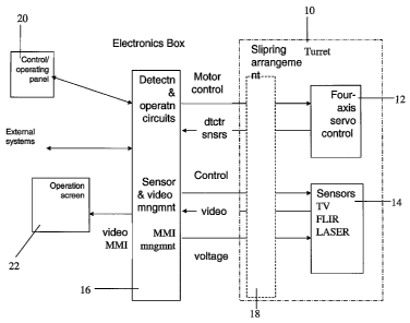
Reference is now made to Fig. 1, which is a simplified diagram showing the
two-part system arrangement for a rotatable observation turret. A turret 10 is
fully
rotatable and includes four axis servo-control 12 to control rotation. One or
more
sensor devices 14 such as FLIR devices, laser devices, video cameras and the
like are
typically mounted in the turret. Each of the sensor devices 14 receives a
control input
and produces an output. A computer or the like is located in an electronics
box 16
located outside the turret, and, as will be appreciated, the turret rotates in
use but the
box does not. The various devices in the turret have different communication
requirements and standards. Thus a video camera has a very high data rate
output and
may produce either an analog or a digital signal depending on the kind of
camera.
The servo control is part of a control and stabilizing system, and using
signals from a
gyro or the like, or from real time image processing from the cameras. The
servo
control part of the system produces a narrow band control signal, typically
based on
pulse width modulation (PWM), which operates servo-motors in the turret.
In addition to the observation devices and stabilizing devices, there are also
environmental control devices for stabilizing the environment inside the
turret 10.
For example there may be a fan, connected in a control loop with a-temperature
sensor.
As the devices are all incompatible, each device has its own connection or
connections to the outside world. As the turret 10 is fully and freely
rotatable, each
connection uses its own slipring. The slipring connections are part of an
overall turret
slipring arrangement 18. The turret slipring arrangement has only limited
capacity for
CA 02581310 2007-03-21
WO 2006/033105 PCT/IL2005/001009
3
additional sliprings and therefore provides a limit to the number of devices
that can be
inserted into the turret. Furthermore the need to include a new slipring for a
new
device makes installation a complex operation. Indeed, as sensors become more
and
more miniaturized, the possibility arises of fitting more and more sensors
into the
physical confines of the turret. The limiting factor is the capacity for
adding more
rotatable connections and slip rings, and not the physical space in the
turret.
The electronics box 16 comprises position and motion control circuits for
operation of the servomotors and rotation of the turret, management circuitry
for the
video devices and other sensors, and MMI management circuitry which is used
for
handling user commands such as movement, focus, zoom, BIT etc.
The electronics box, which is typically part of the underwing pod on which the
turret is mounted, is connected to a control panel 20, an operating screen 22
and to
other external systems as appropriate. The control panel and operating screen
may be
located in the cockpit of an aircraft to allow on board control. Alternatively
they may
be located at a remotely located control center.
There is a widely recognized need for, and it would be highly advantageous to
have, a communication link for a rotating turret which is devoid of the above
limitations.
SUMMARY OF THE INVENTION
According to one aspect of the present invention there is provided a
communication system for a rotating turret having a plurality of electronic
components, the system comprising:
a first aggregated communication link connecting between said turret and
external electronics, and
a first internal communication switch located within said turret for
connecting
each of said plurality of electronic devices to a channel of said aggregated
communication link.
Preferably, said first communication switch manages respective channels for
said plurality of electronic devices.
Preferably, some of said plurality of devices are connected to outward
channels for passing data from said devices to said external electronics, and
some of
CA 02581310 2007-03-21
WO 2006/033105 PCT/IL2005/001009
4
said plurality of devices are connected to inward channels for passing data
from said
external electronics to said devices.
Preferably, said first communication link is further configured with a power
connection to provide power to said plurality of devices within said turret.
Preferably, said first communication link is a wired link having a slip ring
connection.
Preferably, said first communication link is provided in parallel with a power
connection for providing power to said turret.
Preferably, said first communication link is a wireless link.
Preferably, said communication system is any one of a group comprising an
IR link, a microwave link, an optical link, a LASER link, an ultrasound link,
and a
radio link.
Preferably, said power connection comprises a slip ring.
Preferably, said rotating turret is a turret configured to be free to carry
out
unlimited rotations in a given sense.
In one embodiment, said rotating turret is a turret suitable for carrying out
observations from a vehicle.
The vehicle may be an airborne vehicle, an airborne platform, a waterborne
craft, or a land craft, and more particularly a fixed wing aircraft, a
helicopter, an
unmanned aerial vehicle, a balloon, a ship, a hovercraft, a hydrofoil, a boat,
a
submarine, an unmanned water craft, a tank, an armoured car, a reconnaissance
vehicle, or an autonomous land vehicle such as a robot.
Alternatively, said turret is configured within a stationary installation.
The stationary installation may be any one of a watchtower, a mast, a lookout
post, a bunker, a border post, and an electronic fence.
Preferably, said electronic components comprise observation devices.
Preferably, said observation devices are one or more of a radar device, a
LASER-based observation device, a video camera, a still.camera, a FLIR device,
and
an image intensifier.
The turret may comprise a first external communication switch for routing
between said communication link and said external electronics.
Preferably, said external electronics are configured for carry out processing
of
image data frorn said electronic components.
CA 02581310 2007-03-21
WO 2006/033105 PCT/IL2005/001009
Preferably, said electronic components comprise at least one observation
device and at least one turret rotation device and wherein a feedback loop
over said
aggregated communication link is formed to use processed image data to modify
a
position of said turret.
5 Preferably, said first aggregated communication link is a digital
communication link.
Preferably, said first aggregated communication link comprises an optical
fibre.
Preferably, said optical fibre is a monomode fibre.
Preferably, said first internal communication switch comprises multiplexing
functionality for multiplexing signals from said electronic devices onto
respective
channels.
In an embodiment, said first internal communication switch comprises
demultiplexing functionality for demultiplexing signals from said channels to
be
routed to respective devices_
Preferably, said first external communication switch comprises multiplexing
functionality for multiplexing signals from said external electronics onto
respective
channels for intended ones of said electronic devices.
Preferably, said first external communication switch comprises demultiplexing
functionality for demultiplexing signals from said channels to be routed to
said
external electronics.
Preferably, said first communication link is a control link for passing
control
signals, and wherein there is provided a second communication link, having a
second
internal communication switch, for passing video signals outwardly from said
turret to
a second external communication switch.
According to a second aspect of the present invention there is provided a
method of communicating between a plurality of electronic components in a
rotating
turret and external electronics in a relatively non-rotating exterior, the
method
comprising:
connecting each of said plurality of electronic devices to a communication
switch internal to said rotating turret,
connecting said cornmunication switch to a aggregated communication link
connecting the interior of said rotating turret to said relatively non-
rotating exterior,
CA 02581310 2007-03-21
WO 2006/033105 PCT/IL2005/001009
6
connecting said aggregated communication link to said external electronics in
said relatively non-rotating exterior, thereby to provide respectively
continuous
communications channels between each device, said aggregated communication
link
and said external electronics.Unless otherwise defined, all technical and
scientific
terms used herein have the same meaning as commonly understood by one of
ordinary skill in the art to which this invention belongs. The materials,
methods, and
examples provided herein are illustrative only and not intended to be
limiting.
Implementation of the method and system of the present invention involves
performing or completing certain selected tasks or steps manually,
automatically, or a
combination thereof. Moreover, according to actual instrumentation and
equipment
of preferred embodiments of the method and system of the present invention,
several
selected steps could be implemented by hardware or by software on any
operating
system of any firmware or a combination thereof. For example, as hardware,
selected
steps of the invention could be implemented as a chip or a circuit. As
software,
selected steps of the invention could be implemented as a plurality of
software
instructions being executed by a computer using any suitable operating system.
In
any case, selected steps of the method and system of the invention could be
described
as being performed by a data processor, such as a computing platform for
executing a
plurality of instructions.
BRIEF DESCRIPTION OF THE DRAWINGS
The invention is herein described, by way of example oiily, with reference to
the accompanying drawings. With specific reference now to the drawings in
detail, it
is stressed that the particulars shown are by way of example and for purposes
of
illustrative discussion of the preferred embodiments of the present invention
only, and
are presented in order to provide what is believed to be the most useful and
readily
understood description of the principles and conceptual aspects of the
invention. In
this regard, no attempt is made to show structural details of the invention in
more
detail than is necessary for a fundament:al understanding of the invention,
the
description taken with the drawings making apparent to those skilled in the
art how
the several forms of the invention may be embodied in practice.
In the drawings:
CA 02581310 2007-03-21
WO 2006/033105 PCT/IL2005/001009
7
FIG. 1 is a simplified block diagram showing the electronic system
arrangement for a prior art rotatable turret;
FIG. 2 is a simplified block diagram showing an electronic system
arrangement for a rotatable turret according to a first ernbodiment of the
present
invention;
FIG. 3 is a simplified schematic diagram of a pod having a turret and a base
and showing internal and external switches and a single data link
therebetween, in
accordance with a preferred embodiment of the present invention,
FIG. 4 is a simplified diagram showing connections to the inner and outer
switches in accordance with a preferred embodiment of the present invention,
and
FIG. 5 is a simplified diagram showing separate control and video links each
with separate inner switches and separate outer switches, in accordance with a
preferred embodiment of the present invention.
DESCRIPTION OF THE PREFERRED EMBODIMENTS
The present embodiments comprise an observation turret having a
communication switch located within the turret and connected to the various
observation and servo devices. The switch in turn is connected to an
aggregated data
link, typically a wideband digital data link, which connects between the
turret itself
and the external world. The switch permits all of the devices in the turret to
use
separate channels on the same data link for communication, and the result is a
more
robust turret system with a much reduced need for connections. The wideband
link
may be a wireless link such as radio or IR or microwave or ultrasound or an
optical
link or the like. Alternatively it may be a wired link or a link using
waveguides. The
number of slip rings is greatly reduced and additional devices can be added at
will as
long as there is space in the turret, and capacity at the switch and over the
link. No
additional rotating connections are needed when adding new components.
The principles and operation of a turret system according to the present
invention may be better understood with reference to the dxawings and
accompanying
description.
Before explaining at least one embodiment of the invention in detail, it is to
be
understood that the invention is not limited in its application to the details
of
CA 02581310 2007-03-21
WO 2006/033105 PCT/IL2005/001009
8
construction and the arrangement of the components set forth in the following
description or illustrated in the drawings. The invention is capable of other
embodiments or of being practiced or carried out in various ways. Also, it is
to be
understood that the phraseology and terminology employed herein is for the
purpose
of description and should not be regarded as limiting.
Reference was made above to Fig. 1, which illustrates the two part electrical
system arrangement for a currently known observation turret or turret for any
other
purpose. As explained, the arrangement requires multiple rotary connections
with
separate slip rings, and is limited in the number of devices it can support.
It is also
1o limited in its ability to support devices that require multiple
connections, for example
devices intended to be connected to a parallel databus.
It is noted that rotating turrets may be for stationary mounting, say at
hilltop
observation platforms, on watchtowers, on masts, on lookout posts, bunkers, at
border
posts, and on electronic fences, including border walls, prison walls and the
like.
Alternatively rotating turrets can be used in all kinds of airborne craft
including fixed wing aircraft, helicopters, unmanned aerial vehicles (UAVs) of
all
kinds, space-borne craft, waterborne craft including ships, hovercraft,
hydrofoil craft,
boats, submarines etc. and land vehicles such as tanks, armoured cars,
unmanned
robots, reconnaissance vehicles and the like.
Reference is now made to Fig. 2, which illustrates the electrical system
arrangement for a rotatable turret according to a first preferred embodiment
of the
present invention. Parts that are the same as in Fig. 1 are given the same
reference
numerals and are not referred to again except as necessary for understanding
the
present embodiment. Turret 10 again has a servo control system 12 which may
include a plurality of servo control devices, and a series of observation
devices 14. It
also includes an aggregate communication link 30 which connects between the
turret
and external electronics such as electronics box 16, and furthermore has an
internal
data or communication switch 32, which is located within the turret and which
connects to each of the electronic devices in the turret and digitizes or
otherwise
renders their signals compatible with the communication link 30, and then sets
up
channels on the link as required for each of the devices. That is to say, if
the link is a
digital link and any of the devices produce analog output, then the switch
includes an
CA 02581310 2007-03-21
WO 2006/033105 PCT/IL2005/001009
9
A/D converter. A digital link is preferred as it is easier to multiplex
channels
together.
The link preferably has the overall broadband capacity to manage all of the
devices and the switch has sufficient processing power to provide say a video
camera
with a broadband output channel and a stability sensor with a narrow band
output
channel. Having a communication switch within the turret goes against the
general
trend in the art which favors carrying out all processing externally.
A second data communication switch 32 is located at the external end of the
link to digitize signals going towards the turret as necessary, and provide
them witli
1o channels, and also to extract outgoing signals from the link and direct
them to the
appropriate devices or ports outside of the turret.
An advantage of the single link is that all that is needed is a rotatable
connection for the data link and a second rotatable connection to provide a
power
supply to the internal environment of the turret. If the link 30 is a wireless
link of
some kind then the only rotatable connection that is needed is for a power
supply to
provide electrical power to the turret. In either case the total number of
slip rings
needed is minimal, ideally just two, hence reducing the likelihood of failure
within
the system and furthermore new devices may be added to the turret as long as
there is
capacity on the link, witliout the need to introduce an additional slip ring.
Regarding
the question of capacity it is noted that the typical communication switch has
a buffer,
allowing less critical data to be queued, so that the link need only provide
an average
system capacity, not a peak capacity.
Suitable candidates for a wireless link include an IR link, a microwave link,
an
optical link, a LASER link, an ultrasound link, and a radio link.
Alternatively, as
mentioned above, a wired or waveguide link can be used. Typical observation
devices
likely to be placed inside a turret include both active and passive
observation devices,
for example radar of different wavelengths, a laser-based observation device,
a video
camera, a still camera, a FLIR device, and an image intensifier.
Use of a digital link makes it simple to use a digital video camera, for
example
using Mpixel or HDTV formats. The format in which the data is produced at the
camera may be retained over the link and fed as is to the video card at the
external
electronics for real time display with minimal intermediate processing. It may
be
CA 02581310 2007-03-21
WO 2006/033105 PCT/IL2005/001009
added that the use of a digital signal format across the link preserves the
integrity of
the image to a greater extent than the prior art analog systems.
In addition it is possible to place a local digital controller on each pivot
of the
rotatable turret. The controllers may close a local control loop to provide
say stability
5 to the turret whilst obtaining target finding and tracking instructions from
the
electronics box 16 via the link 30.
As the signal received from the link is digital, the complexity of the
processing circuits in the image processing cards that receive and process the
image
data is reduced, since there is no need to digitize the signals at the card,
in contrast
10 with the prior art.
For the same reason, data recording is simplified. The actual data as provided
by the link 30 can be recorded in a digital memory, whether magnetic, solid
state or
any other and/or can be transmitted to a remote location for remote viewing,
processing or storage using existing digital communication infrastructure.
Digital image data, depending on the format, can be output directly to the
screen. The data can be displayed on LCD screens and the computer can be
relieved
of the burden of the display task.
A particular advantage of the single data link of the embodiment of Fig. 2
concerns the rapidly increasing numbers of miniature sensors. With the current
art,
the limit on the number of devices in the turret has nothing to do with the
size or
complexity of the devices but rather with the number of connections needed.
Thus
the rotating turret has been unable to benefit from the increasing
miniaturization of
numerous kinds of sensors. With the single aggregated preferably digital link
of the
present embodiments, the only barriers to the number of sensors that can be
inserted
into the turret is the physical space in the turret, connection capacity in
the switch, and
the overall data capacity in the link. For example micro-electro-mechanical
systems
(MEMS) sensors can be inserted at will to provide high levels of stability and
navigability for very little extra weight.
Reference is now made to Fig. 3, which is a simplified schematic diagram
showing a turret with two switch units and a multi-channel link in between,
according
to a preferred embodiment of the present invention. A pod 40 comprises a
turret 42
and base 44. Turret 42 has a first or internal communication or data switch
46, which
is as described above. A second external communication or data switch 48 lies
in the
CA 02581310 2007-03-21
WO 2006/033105 PCT/IL2005/001009
11
base 44 and in between the two switches is a multi-channel data link 50. In
the
embodiment of Fig. 3 the link is an optical link using optical waveguides. The
optical
link may be a single multimode fibre or multiple single mode fibres as
convenient.
Reference is now made to Fig. 4, which is a simplified block diagram
illustrating
connections to the two switches. Parts that are the same as in previous
figures are
given the same reference numerals and are not referred to again except as
necessary
for understanding the present embodiment. Devices, sensors and motors, 12 and
14,
inside the turret 10 are connected to the internal switch 46. Processors,
control and
display panels and the like are connected to external switch 48 and the two
switches
are linked, as described above by an aggregated data link 50.
In a preferred embodiment the capacity of the link 50 is of an order of
magnitude greater than the capacity at the output side of the switch. In a
first example
of capacity requirements, on the assumption of a 50MBPS compressed video
signal
from a video camera, which signal has to be combined with control and other
signals,
a 100MBPS output capacity at the switch is sufficient but the link should be
IGBPS,
say using GigE (Gigabit Ethernet). In a second example, for a non-compressed
video
output, say 0.3GBPS, a 1 GBPS output can be used with a 10GBPS link.
In a separate embodiment it is possible to provide two separate links, one
high
capacity link for the video and one smaller link for the control and other
system
traffic. The second embodiment is illustrated in Fig. 5, which is similar to
Fig. 4 but
the previous inner switch is now split into a control inner switch 70 and a
video inner
switch 72. All devices in the turret are connected to the control inner switch
and
those that give a video output, here FLIR 74 and CCD 76, are additionally
connected
to the video inner switch. A control outer switch 78 is connected via control
link 80
to the control inner switch 70, and video outer switch 82 is connected via
video link
84 to video inner switch 72.
In the case of Fig. 5, the above examples work as follows:
In the first example, on the assumption of a 50MBPS compressed output
signal from a video camera, which signal no longer has to be combined with
control
and other signals, a 100MBPS output capacity at the switch is sufficient but
the link
should be 1GBPS, say using GigE. In a second example, for a non-compressed
video
output, at a higher level of 0.5GBPS, a 1 GBPS output can be used with the
same
CA 02581310 2007-03-21
WO 2006/033105 PCT/IL2005/001009
12
10GBPS link as before. In addition the control link 80 is preferably provided,
in
either case with 100MBPS at the switch output and 1 GBPS in the link itself.
Video is typically transmitted digitally, and preferred formats include DVS
50,
DVS 25, MPEG 4 (H.261, H.264), sent using RPT packets over UDP/IP. The
remaining signals can be transmitted using RS-232, RS-422, RS-485 digital
signaling
in discrete transmission channels for each major component, using TCP/IP
packets.
The video signals are preferably multicast so that they can be received by
multiple receiving devices. Control signals from the processors to the turret
can also
be multicast, as they can be received by multiple devices as necessary. The
control
signals from the turret to the processors, including servo processors, are
preferably
unicast.
It is expected that during the life of this patent many relevant observation
devices and systems, and turret mounted components and systems will be
developed
and the scopes of the corresponding terms herein are intended to include all
such new
technologies a priori.
It is appreciated that certain features of the invention, which are, for
clarity,
described in the context of separate embodiments, may also be provided in
combination in a single embodiment. Conversely, various features of the
invention,
which are, for brevity, described in the context of a single embodiment, may
also be
provided separately or in any suitable subcombination.
Although the invention has been described in conjunction witli specific
embodiments thereof, it is evident that many alternatives, modifications and
variations
will be apparent to those skilled in the art. Accordingly, it is intended to
embrace all
such alternatives, modifications and variations that fall within the spirit
and broad
scope of the appended claims. All publications, patents and patent
applications
mentioned in this specification are herein incorporated in their entirety by
reference
into the specification, to the same extent as if each individual publication,
patent or
patent application was specifically and individually indicated to be
incorporated
herein by reference. In addition, citation or identification of any reference
in this
application shall not be construed as an admission that such reference is
available as
prior art to the present invention.