Note: Descriptions are shown in the official language in which they were submitted.
CA 02581768 2007-03-09
IP 00568 2004
DISPENSER FOR A DRAWER-TYPE DISHWASHER
CROSS-REFERENCE TO RELATED APPLICATION
The present application claims the benefit of U.S. Provisional
Patent Application Serial No. 60/793,306 filed April 20, 2006 entitled
"Dispenser For a Drawer-Type Dishwasher."
BACKGROUND OF THE INVENTION
1. Field of the Invention
The present invention pertains to the art of drawer-type
dishwashers and, more particularly, to a dispenser for storing and
releasing detergent and/or rinse aid into a wash chamber of a drawer-type
dishwasher.
CA 02581768 2007-03-09
IP 00568 2004
2. Discussion of the Prior Art
In general, dishwashers having a pull-out drawer are known in the
art. In some models, the dishwasher will include an upper pull-out
drawer forming a washing chamber for washing smaller objects such as
glassware, utensils, small plates and the like, and a lower conventional-
type dishwasher. In other models, the dishwasher will include upper and
lower pull-out washing chambers or just simply include a single pull-out
type washing chamber. In any event, the pull-out washing chamber must
be provided with a dispenser that releases detergent and/or rinse aid into
io the washing chamber during a washing operation.
In conventional dishwashers, dispensers for detergent and rinse aid
are typically located on a door assembly. At the start of a washing
operation, the door assembly is opened, the dispenser loaded and, after
loading dishes, the door assembly is closed. During the washing
operation, a mechanism opens the dispenser allowing detergent to fall
into the dishwasher. However, unlike conventional dishwashers, drawer-
type dishwashers do not include a door assembly that enables a consumer
to load detergent in a horizontal orientation for dispensing in a vertical
orientation.
Detergent dispensers for a drawer-type dishwasher are typically
mounted to or formed in a front wall of the drawer. One dispenser design
includes a pull-out or pivoting chamber. With this design, the dispenser
is loaded with detergent and pivoted back into a receptacle formed in the
front wall of the drawer. At a prescribed time during the washing
operation, a jet of water is directed from a nozzle formed in the receptacle
into the dispenser. The jet of water washes the detergent through an
2
CA 02581768 2007-03-09
IP 00568 2004
opening formed in a bottom of the receptacle and into the drawer. While
effective, this design requires tubing to be formed into the drawer during
manufacturing which raises the complexity of manufacturing and the
overall cost of the appliance.
Other designs utilize disposable containers that are supported on a
side wall of the drawer. A single or multi-use container, coupled to an
actuation mechanism, dispenses a prescribed amount of detergent at a
predetermined point in the washing operation. Once the container is
depleted, a new container is positioned in the drawer. While this method
io is also effective, consumers are faced with limited choices. That is, not
all detergent manufacturers have developed or offer containers of this
type.
Based on the above, there exists a need for a dispenser for a
drawer-type dishwasher. More specifically, there exists a need for a
dispenser for releasing detergent and/or rinse aid that can be mounted to a
side wall of the dishwasher without requiring special jets to wash the
detergent into the drawer or specific, single use containers to retain and
release the detergent during a wash operation.
SUMMARY OF THE INVENTION
The present invention is directed to a dispenser for a drawer-type
dishwasher. The dispenser is mounted to one of front and opposing side
walls of a basin or wash tub slidably supported in an outer body of the
dishwasher. In accordance with the invention, the dispenser includes a
3
CA 02581768 2007-03-09
IP 00568 2004
main body portion, a reservoir formed in the main body portion for
receiving detergent, and a lid hingedly mounted to the main body portion
for selectivity closing the reservoir. In further accordance with the
invention, the reservoir includes front, rear, bottom and opposing side
walls with one of the front, rear and opposing side walls being provided
with a drainage port.
In still further accordance with the invention, the dispenser is
provided with a first actuator for manually operating the lid and a second
io actuator for automatic operation of the lid. The first or manual actuator
is
constituted by a button, lever or other manually activated device that
enables a consumer to open the dispenser lid to add detergent. The
second or automatic actuator is provided to open the dispenser lid at a
predetermined point of a washing operation. Once open, washing fluid
flowing from a wash arm of the dishwasher enters the reservoir causing
the detergent to wash over the walls into the basin. The drainage port
provides an opening that permits any residual washing fluid in the
reservoir to drain into the wash tub. In addition to detergent, the
dispenser could also be provided with a reservoir for retaining and
selectively releasing rinse aid.
Additional objects, features and advantages of the present
invention will become more readily apparent from the following detailed
description of preferred embodiments when taken in conjunction with the
drawings wherein like reference numerals refer to corresponding parts in
the several views.
4
CA 02581768 2007-03-09
IP 00568 2004
BRIEF DESCRIPTION OF THE DRAWINGS
Figure 1 is an upper right perspective view of a dishwasher
incorporating a detergent dispenser constructed in accordance with the
present invention;
Figure 2 is an enlarged upper right perspective view of the
detergent dispenser of Figure 1 constructed in accordance with one
embodiment of the present invention;
Figure 3 is an is a perspective view of the detergent dispenser of
Figure 2 illustrated with a lid portion of the dispenser in an open
I o configuration;
Figure 4 is a rear perspective view of the detergent dispenser of
Figure 2 illustrating an actuator portion of a dispensing mechanism;
Figure 5 is a rear perspective view of the detergent dispenser of
Figure 2 illustrating a linkage portion of the dispensing mechanism;
Figure 6 is a perspective view of the detergent dispenser
constructed in accordance with a second embodiment of the present
invention;
Figure 7 is an is a perspective view of the detergent dispenser of
Figure 6 illustrated with a lid portion of the dispenser in an open
configuration;
5
CA 02581768 2007-03-09
IP 00568 2004
Figure 8 is a rear perspective view of the detergent dispenser of
Figure 6 illustrating an actuator portion of a dispensing mechanism
constructed in accordance with the second embodiment; and
Figures 9-14 illustrate a still further embodiment of the invention.
s DETAILED DESCRIPTION OF THE PREFERRED
EMBODIMENTS
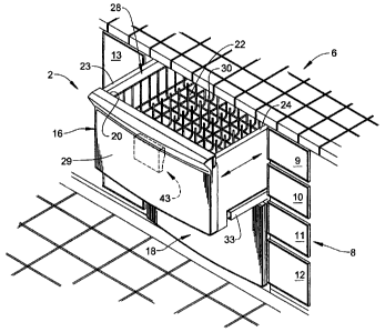
With initial reference to Figure 1, a dishwasher constructed in
accordance with the present invention is generally indicated at 2. As
shown, dishwasher 2 includes an outer body 4 arranged below a kitchen
Io countertop 6. Also below kitchen countertop 6 is shown cabinetry 8
including a plurality of drawers 9-12, as well as a cabinet door 13.
Although the actual dishwasher into which the present invention may be
incorporated can vary, the invention is shown in connection with
dishwasher 2 depicted as a dual cavity dishwasher having an upper
15 washing unit 16 and a lower washing unit 18. Upper and lower washing
units 16 and 18 take the form of drawers capable of operating either
singly or in combination.
In the embodiment shown, upper washing unit or drawer 16 is
shown to include a front wall 20, rear wall (not shown), bottom wall 22
2o and opposing side walls 23 and 24 that collectively define a wash tub or
basin 28. In a manner known in the art, basin 28 is provided with a dish
rack 30 for supporting various objects, such as dishware, glassware and
the like, that are exposed to a washing operation. In a manner also known
6
CA 02581768 2007-03-09
IP 00568 2004
in the art, upper drawer 16 is slidingly supported within an outer body 4
through a pair of extensible support guides, one of which is indicated at
33. In addition, it should be understood that, although not shown, each
drawer 16, 18 is provided with a corresponding lid member (not shown)
that selectively seals a respective basin 28. In any event, the above
description is provided for the sake of completeness and to enable a better
understanding of the drawings. The present invention is particularly
directed to a dispenser, such as indicated at 43, for selectively storing and
subsequently releasing detergent and/or rinse aid for a washing operation.
With reference to Figures 2 and 3, dispenser 43 includes a main
body portion 46 having front, rear, top, bottom and opposing side
portions 50-55. Main body portion 46 includes a first reservoir 60 for
receiving and selectively releasing dishwashing detergent and a second
reservoir 62 for storing and selectively releasing rinse aide. Reservoir 60
is sized and shaped so as to receive a variety of forms of dishwashing
detergent, such as liquid, solid particulate and formed blocks. Second
reservoir 62 is provided with a lid 64 having a raised area 65 which
enables a consumer to readily grasp and remove lid 64 in order to expose
second reservoir 62, thereby permitting rinse aid to be introduced therein.
2o As will be detailed more fully below, the rinse aid is ejected or released
from second reservoir 62 through an opening 67 provided in front portion
50 during select portions of the washing operation, particularly just prior
to a final rinse cycle.
As best shown in Figure 3, first reservoir 60 includes a front wall
70, rear wall 71, bottom wall 72 and opposing side walls 73 and 74 which
collectively define a chamber 75. In accordance with the invention,
7
CA 02581768 2007-03-09
IP 00568 2004
chamber 75 is provided with a drain port 80 located adjacent bottom wall
72. Drain port 80 is provided to allow detergent to be rinsed from first
reservoir 60. That is, drain port 80 is sized so as to ensure that liquid
(gel) or particulate detergent can be maintained within chamber 75 until
such a time as that detergent is diluted with water to form a washing
solution. Once diluted, the detergent is capable of passing through drain
port 80 into basin 28.
In order to prevent prematurely exposing the detergent held within
first reservoir 60 to a flow of diluting water, dispenser 43 is provided with
Io a lid 89 pivotally mounted relative to main body portion 46. As shown,
lid 89 includes front, rear, top and opposing side sections 91-95 which, in
one preferred arrangement, collectively define a third reservoir 96. Third
reservoir 96 can be employed to store or hold detergent for providing a
pre-wash to dishware located within basin 28. Lid 89 is also shown to
include an extension 100 which selectively closes drain port 80 when lid
89 is in a closed position. Also, lid 89 is provided with a recess 102
which, as will be discussed more fully below, is provided to selectively
retain lid 89 in a closed position.
In accordance with the invention, dispenser 43 is provided with
2o both a first or manual actuator 110 (see Figure 3) and a second or
automatic actuator 111 (see Figure 4). As best seen in Figure 3, manual
actuator 110 includes a first end portion 114 which is pivotally mounted
relative to main body portion 46 and leads to a second end portion 116.
In accordance with the embodiment shown, manual actuator 110 includes
a substantially vertical, planar surface 118 which is provided with a raised
rib 119. With this arrangement, raised rib 119 cooperates with recess 102
8
CA 02581768 2007-03-09
IP 00568 2004
to selectively retain lid 89 in the closed position. In order to cause lid 89
to shift to the open position, manual actuator 110 is pivoted about first
end 114 to allow raised rib 119 to disengage from recess 102. At this
point, a spring (not shown) provides a biasing force that causes lid 89 to
s shift from the closed position (Figure 2) to the open position (Figure 3).
Manual actuator 110 is typically employed to enable the loading and/or
visual inspection of first reservoir 60 by a consumer prior to initiating a
washing operation. During the washing operation, lid 89 is automatically
shifted from the closed position to the open position to expose any
Io detergent contained therein to jets of washing fluid as discussed further
below.
In accordance with the preferred embodiment of the present
invention illustrated in Figures 4 and 5, automatic actuator 111 includes a
linear actuator 134, which can be in the form of, for example, a wax
Is motor or solenoid, operatively coupled to a linkage system 137. Linear
actuator 134 includes an output shaft or first actuating element 139 which
is adapted to engage and shift both a second actuating element 142 that is
connected to a piston (not shown) and linkage system 137. The piston
resides within a charging chamber 144 that is in fluid communication
20 with second reservoir 62 and, as will be discussed more fully below,
employed to discharge rinse aid into basin 28 during a select portion of
the washing operation.
Referring to Figure 5, linkage system 137 is shown to include a
third actuating element 154 which is pivotally connected to a fourth
25 actuating element 156. As shown, third actuating element 154 includes a
first end 159 that is provided with a lever arm 160. First end 159 extends
9
CA 02581768 2007-03-09
IP 00568 2004
to a second end 161 that includes a pivot pin 163. In accordance with the
invention, lever arm 160 is adapted to be operated on by first actuating
element 139, while also being connected to second actuating element 142.
In order to provide a degree of stability to linkage system 137, third
actuating element 154 nests within a guide channel 165 formed by raised
sections 166 and 167 formed on rear wall 51 of main body portion 46. In
any event, fourth actuating element 156 includes a first end 170 having an
opening (not separately labeled) that receives pivot pin 163. First end
170 extends to a second end 172 through an offset or stepped portion 173.
io Second end 172 is shown to include a collar (not separately labeled)
which matingly engages with a shaft 175. Shaft 175 is operatively
associated with manual actuator 110 such that operation of linkage
system 137 rotates shaft 175 causing lid 89 to automatically shift from the
closed position of Figure 2 to the open position of Figure 3.
In accordance with the invention, after charging first reservoir 60
with detergent and second reservoir 62 with rinse aid through lid 64, a
consumer may initiate a washing operation in basin 28. Upon
commencement of the washing operation, jets of washing fluid are
directed about basin 28 from various upper and lower wash arms (not
shown). If third reservoir 96 has been charged with detergent, the jets of
washing fluid dilute the detergent contained therein to initiate a first or
pre-wash operation. After the completion of any pre-wash operation,
automatic actuator 111 is activated through a control system (not shown).
More specifically, a first signal is sent to linear actuator 134 to initiate
shifting of first and second actuating elements 139 and 142, while also
acting upon lever arm 160 to raise third actuating element 154. Third
actuating element 154 then acts upon fourth actuating element 156
CA 02581768 2007-03-09
IP 00568 2004
resulting in the rotation of shaft 175 and the opening of lid 89. Once lid
89 is open to expose first reservoir 60, jets of washing fluid impinge upon
detergent contained within first reservoir 60 creating a detergent solution
employed during a second or main wash operation.
Prior to a final rinse cycle, the dishwasher control (not shown)
signals linear actuator 134 a second time, causing first actuating member
139 to fully retract, thereby raising second actuating element 142 and
causing the piston (not shown) to draw rinse aid into charging chamber
144 from second reservoir 62. At the initiation of the final rinse cycle,
io linear actuator 134 is de-energized, forcing first and second actuating
elements 139 and 142 downward and causing the piston to move into
chamber 144, thereby forcing rinse aid through opening 67 into basin 28.
In a manner known in the art, the rinse aid mixes with rinse water so as to
ensure a clean, final rinse to any dishware contained within basin 28.
Reference will now be made to Figures 6-8 in describing a second
embodiment of the present invention. In accordance with the
embodiment shown, a dispenser 185 includes a main body portion 190
having front, rear, top, bottom and opposing side portions 193-198.
Dispenser 185 is shown to include a first reservoir 210 for receiving
2o detergent in liquid, particulate or solid form, as well as a second
reservoir
214 for receiving and storing rinse aid. In a manner analogous to that set
forth above, second reservoir 214 is provided with a lid 216 having a
raised portion 217. Raised portion 217 enables a consumer to readily
grasp and open lid 216 to expose second reservoir 214 and enable the
addition of rinse aid. As will be discussed more fully below, front wall
193 of main body portion 190 is provided with an opening 219 which
I1
CA 02581768 2007-03-09
IP 00568 2004
serves as a passage to enable rinse aid to be guided from second reservoir
214 into basin 28.
As best illustrated in Figure 7, first reservoir 210 includes a front
wall 221, a rear wall 222, a bottom wall 223 and opposing side walls 224
and 225 which collectively define a chamber 252. In the embodiment
shown, arranged on front wall 221 is a drain port 256 which, in a manner
corresponding to that described above, is sized and shaped to ensure that
detergent remains within chamber 252 until diluted with washing fluid.
That is, once chamber 252 is exposed to jets of washing fluid, a
io detergent/washing fluid mix can overflow sides 221-225 of chamber 252
while any remaining detergent mix can exit through drain port 256.
First reservoir 210 is provided with a lid 264, having front, rear,
top, and opposing side wall portions 267-271, pivotally mounted relative
to main body portion 190 through a hinge pin 275. As further shown,
front wall portion 267 serves as a cover for drain port 256 when lid 264 is
in the closed position. Lid 264 is also provided with a boss 277 arranged
on side wall 270 which, in a manner that will be detailed more fully
below, is adapted to selectively retain lid 264 in the closed position.
Dispenser 185 is provided with a first or manual actuator 286 (see
2o Figures 6 and 7) which enables a consumer to charge first reservoir 252
with detergent, as well as a second or automatic actuator 287 (see Figure
8) which selectively operates lid 264 during a portion of the washing
operation. Manual actuator 286 includes a first end 289 that is pivotally
mounted and spring biased relative to main body portion 190. First end
289 extends to a second end. 292 having formed therein a depression 293.
12
CA 02581768 2007-03-09
IP 00568 2004
Depression 293 enables easy manipulation of manual actuator 286 by a
consumer. As best shown in Figure 7, manual actuator 286 also includes
a substantially planar surface 297 positioned adjacent first reservoir 210.
Formed in planar surface 297 is a recess 299 that is adapted to cooperate
with boss 277 to selectively retain lid 264 in the closed position. When it
is desirable to open lid 264, a consumer simply need pivot manual
actuator 286 against a biasing force about first end 289. Pivoting manual
actuator 286 causes recess 299 to disengage from boss 277 thereby
allowing lid 264 to automatically shift to the open position. More
1o specifically, given that lid 264 includes a spring (not shown), once boss
277 disengages from recess 299, lid 264 is biased into the open position.
Referring to Figure 8, in order to automatically open lid 264 during
the washing operation, automatic actuator 287 includes an electrically
operated linear actuator, such as, for example, a wax motor or solenoid,
Is indicated generally at 313. Linear actuator 313 is operatively coupled to
a linkage system 316 through a first actuating element 319. In general,
when a control (not shown) activates linear actuator 313, first actuating
element 319 engages with linkage system 316 to automatically operate lid
264. Towards that end, linkage system 316 defines a second actuating
2o element 353 pivotally connected to a first end 357 of a third actuating
element 358 by a pin 359. More specifically, second actuating element
353 is operatively associated with a piston assembly (not shown)
arranged in a charging chamber 365. First end 357 extends to a second
end 368 which is provided with an angled surface 370 that is operatively
25 connected to a fourth actuating element 380. Fourth actuating element
380 includes a first end 3 84 provided with a corresponding angled surface
386 which extends to a second end 390 that is provided with an opening
13
CA 02581768 2007-03-09
IP 00568 2004
392. Opening 392 receives a shaft 396 that is keyed to manual actuator
286.
With this particular arrangement, once a control (not shown)
energizes linear actuator 313, first actuating element 319 extends outward
causing third actuating element 358 to pivot about pin 359. Initially, first
actuating element 319 extends only a small amount, causing angled
surface 370 to ride against angled surface 386. This movement causes
fourth actuating element 380 to pivot and shaft 396 to rotate so as to
deflect manual actuator 286 in order to allow lid 264 to open. In this
Io manner, first reservoir 210 is exposed to jets of washing fluid allowing
the detergent contained therein to become diluted and enter into basin 28.
As the washing operation progresses, first actuating element 319 extends
further causing second actuating element 353 to shift relative to charging
chamber 365 creating a vacuum in chamber 365. The vacuum causes
rinse aid to be withdrawn from second reservoir 214 and directed into
charging chamber 365. Once charging chamber 365 contains rinse aid, a
signal is sent to linear actuator 313 which causes first actuating element
319 to retract, forcing rinse aid from charging chamber 365 out opening
219 and into basin 28. Preferably, the signal is sent to linear actuator 313
2o during a final rinse phase such that the rinse aid mixes with the fluid in
wash tub 28 to ensure a clean, final rinse.
Reference will now be made to Figures 9-14 in describing a third
embodiment of the present invention. In accordance with the
embodiment shown, a dispenser 500 includes a main body portion 510
having front, rear, top, bottom and opposing side portions 515-520.
Dispenser 500 is shown to include a first reservoir 530 for receiving
14
CA 02581768 2007-03-09
IP 00568 2004
detergent in liquid, particulate or solid form, as well as a second reservoir
531 for receiving and storing liquid rinse aid. In a manner analogous to
that set forth above, second reservoir 531 is provided with a lid 540 have
a raised portion 541. Raised portion 541 enables a consumer to readily
grasp and open lid 540 exposing second reservoir 531 to enable the
addition of liquid rinse aid which, in a manner also corresponding to that
described above, is selectively released from second reservoir 531 into
basin 28 during a rinse cycle portion of an overall washing operation.
As shown, first reservoir 530 is provided with a lid 545, having
Io front, rear, top and opposing side wall portions 546-550, pivotally
mounted relative to main body portion 510 through a pair of rear hinges
552a and 552b. Hinges 552a and 552b allow lid 545 to rotate upward to
expose first reservoir 530. Lid 545 is also provided with a protrusion or
boss 551 (see Figures 10 and 11) arranged on side wall 549 which, in a
Is manner similar to that described above, cooperates with an actuating
mechanism to selectively retain lid 545 in the closed position. That is,
dispenser 500 includes a manual actuator 553 that is selectively operated
by a consumer to expose first reservoir 530 and an automatic actuator
system 555 which is arranged on back wa11516 and controlled by
2o dishwasher 2 to selectively open lid 545, exposing first reservoir 530
during select portions of a washing operation. Automatic actuating
system 555 includes a linear actuator 560, coupled to a linkage system
565 having a plurality of linkage elements, two of which are indicated at
567 and 568, that are operated to selectively dispense either rinse aid and
25 detergent from dispenser 500. However, as the operation of linkage
system 565 directly corresponds to that described above, further
discussion will not be provided herein. Instead, the focus of the third
CA 02581768 2007-03-09
IP 00568 2004
embodiment lies in the particular incorporation and orientation of a third
reservoir or pre-wash chamber 574 into dispenser 500.
As best shown in Figures 9-11, pre-wash chamber 574 is integrally
formed in main body portion 510 and positioned adjacent to first
reservoir 530. Pre-wash chamber 574 is provided with an opening 584
that enables diluted detergent or a pre-washing fluid mixture to drain
from dispenser 500 into washing chamber 28. That is, if a consumer
desires to perform a pre-wash cycle in washing chamber 28, detergent in
liquid, particulate or solid form is placed into pre-wash chamber 574.
Io During the washing operation, washing fluid is directed into pre-wash
chamber 574, causing the detergent contained therein to dissolve and/or
become diluted so as to pass through opening 584 into washing chamber
28. The detergent then mixes with washing fluid and is directed upon
dishware to perform a pre-wash operation.
Based on the above-discussed preferred embodiments, it should be
readily understood that, given the construction of dishwasher 2, the
dispensers of the present invention enable a consumer to charge
dishwashing detergent in a top portion of a dispenser, while enabling or
providing a path for washing fluid to mix with and dilute the detergent for
2o release into the dishwasher. Although described with reference to
preferred embodiments of the invention, it should be readily understood
that various changes and/or modifications can be made to the invention
without departing from the spirit thereof. For instance, while each
dispenser is shown mounted to a respective front wall, other locations,
such as the side walls, would also be acceptable. Also, it should be noted
that the presence of a reservoir in the dispenser lid is but one option, with
16
CA 02581768 2007-03-09
IP 00568 2004
other locations also being acceptable. In general, the invention is only
intended to be limited by the scope of the following claims.
17