Note: Descriptions are shown in the official language in which they were submitted.
CA 02581892 2007-03-27
WO 2006/039318 PCT/US2005/034754
- 1-
SHAVING RAZORS AND RAZOR CARTRIDGES
This invention relates to shaving razors and razor cartridges, and more
particularly to razors for wet shaving.
Users of wet-shave razors generally appreciate a feeling of warmth
against their skin during shaving. The warmth feels good, resulting in a more
comfortable shave.
Various attempts have been made to provide a warm feeling during
shaving. For example, shaving creams have been formulated to react
exothermically
upon release from the shaving canister, so that the shaving cream imparts
warmth to the
skin. Also, razor heads have been heated using hot air, heating elements, and
linearly
scanned laser beams, with power being supplied by a power source such as a
battery.
The invention features razors that include a cartridge portion that is
heated by an electrical circuit and is formed of a material that is capable of
retaining heat
and delivering heat to'a user's skin.
In one aspect, the invention features a razor including (a) a handle, (b) a
head, mounted on the handle, the head including a housing that is positioned
to contact
the user's skin during shaving and that caiTies one or more blades configured
for wet
shaving, and (c) an electrical circuit configured to deliver heat to at least
a portion of the
housing, the electrical circuit including a region of relatively higher
resistance disposed
within or adjacent to the head.
Some implementations may include one or more of the following
features. At least part of the circuit may be disposed within the housing. At
least the
portion of the housing which is to be heated may include a polymer having a
thei-mal
conductivity of at least 1 W/m K, e.g., at least 3 W/m K. The electrical
circuit may be
configured to heat the housing to a surface temperature between about 40 and
70 degrees
C, e.g., between about 32 and 55 degrees C. The electrical circuit may be
configured to
heat the razor for a time period of greater than 15 seconds. The circuit may
be
configured to heat a surface of the housing to a predeterinined maximum
temperature in
a heating time of less than 20 seconds, e.g., less than 10 seconds. The razor
may further
CA 02581892 2007-03-27
WO 2006/039318 PCT/US2005/034754
-2-
include a power source, e.g., a battery, in electrical communication with the
electrical
circuit. The power source may be disposed within the handle. The power source
may
be rechargeable or disposable. The razor may be configured to be mounted in
electrical
communication with a recharging station. The razor may further include an
indicator,
visible to a user of the razor, constructed to provide a visual indication
showing whether
the razor is thermally charged, or indicating the degree to which the razor is
theimally
charged. The razor may also include a guard, and the guard may be formed of a
thermally conductive polymer, e.g., a thermally conductive elastomer. The
region of
relatively high resistance may be disposed in the handle, adjacent to the
housing. The
head may be separable from the handle, and in some cases may be pivotally
mounted
thereon. The head may be mounted on the handle by an electro-mechanical pivot.
A
first portion of the housing may be formed of a thermally conductive polymer,
and a
second portion of the housing may be formed of a non-therma.lly conductive
polymer. A
third, exposed portion of the housing may be formed of a thermochromic
polymer. The
head may be configured to vibrate during shaving. The razor may include a
motor and
an oscillating member mounted on a shaft of the motor, so as to produce such
vibration
when the motor is energized.
In another aspect, the invention features a razor including a handle, a
head, mounted on the handle, and, within the handle, an electrical circuit
configured to
deliver heat to at least a portion of the handle.
The invention also features razor cartridges that include one or more of
the features discussed above. For example, the invention features a razor
cartridge
including (a) a head, constructed to be mounted on a handle, the head
including a
housing that is positioned to contact the user's skin during shaving and that
carries one
or more blades configured for wet shaving, and (b) a heating element disposed
within
the housing and configured for electrical communication with a power source
disposed
within the handle.
In some implementations, the cartridge also includes an electro-
mechanical interconnect device, configured to interconnect the cartridge to a
handle and
to provide electrical communication between the cartridge and handle.
CA 02581892 2007-03-27
WO 2006/039318 PCT/US2005/034754
- 3-
The invention also features razors that include a handle, a head, mounted
on the handle, the head including a housing that is positioned to contact the
user's skin
during shaving and that carries one or more blades configured for wet shaving,
a heat
source configured to deliver heat to a portion of the housing, and a vibrating
mechanism
configured to impart vibration to the head.
The heat source may include, for example, an electrical circuit and/or a
phase change material capable of storing and releasing latent heat from hot
water.
The invention also features methods of shaving using the razors and
cartridges discussed above.
The term "razor", as used herein, unless otherwise indicated refers both to
razors that include a handle and a replaceable cartridge, and to disposable
razors in
which the razor head is fixedly mounted on a handle.
The details of one or more embodiments of the invention are set forth in
the accompanying drawings and the description below. Other features and
advantages
1s of the invention will be apparent from the description and drawings, in
which:
Fig. 1 is a perspective view of a razor.
Fig. 2 is a diagrammatic front view of a razor according to one
embodiment of the invention.
Fig. 3 is a diagrammatic front view of a razor according to an alternative
embodiment of the invention. Fig. 3A is an enlarged, exploded front plan view
of a
cartridge and the upper portion of a handle suitable for use in the embodiment
shown in
Fig. 3.
Fig. 4 is a diagrammatic front view of another alternative embodiment of
the invention.
Fig. 5 is an enlarged, exploded front plan view of a cartridge and the
upper portion of a handle suitable for use in embodiments similar to that
shown in Fig.
2.
CA 02581892 2007-03-27
WO 2006/039318 PCT/US2005/034754
-4-
Fig. 6 is a perspective view of a razor having a pivotally mounted
cartridge. Fig. 6A is an enlarged, exploded detail view of the cartridge and
the upper
portion of the handle shown in Fig. 6.
Fig. 7 is a highly enlarged perspective view of the cartridge shown in
Figs. 6-6A, with the blades removed for clarity.
Fig. 8 is a highly enlarged perspective view of a clip/pivotal interconnect
portion of the cartridge shown in Fig. 7.
Fig. 9 is a diagrammatic view showing a current path through the
cartridge shown in Figs. 6-7.
Fig. 10 is a diagrammatic view showing the current path through the
clip/pivotal interconnect shown in Fig. 8.
Fig. 11 is a diagrammatic view of a razor according to another
embodiinent, including a control circuit.
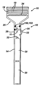
Referring to Fig. 1, a razor 10 includes a handle 14, and, mounted on the
handle, a razor ca.rtridge 16. Razor cartridge 16 includes a molded plastic
housing 18,
which carries a plurality of blades 19 and includes a guard 20. Cartridge 16
is
removably mounted on handle 14 by an interconnect member 25. The housing 18
may
be pivotally or rigidly (non-pivotally) mounted with respect to the handle, as
will be
discussed below.
Guard 20 includes a finned unit molded on the front of housing 16 to
engage and stretch the user's skin; other skin engaging protrusions, e.g., as
described in
U.S Patent No. 5,191,712, which is hereby incoiporated by reference, can be
used.
Guard 20 may be foi-rned of elastomeric material, or may be formed of the same
material
as the rest of housing 16. Preferably, the fins are progressively taller
toward the blades
19, so as to lift the hair gradually for a closer, more comfortable shave.
The razor cartridge 16 may also include other components that improve
the performance or extend the life of the cartridge. For example, a piece of
aluminum
(not shown) may be included at one end to act as a sacrificial anode. Also, a
shaving aid
CA 02581892 2007-03-27
WO 2006/039318 PCT/US2005/034754
- 5-
composite 26 may be provided at the upper edge of the housing 16 to deliver a
lubricious substance to the user's skin, e.g., as described in U.S. Patent
Nos. 5,113,585
and 5,454,164, the disclosures of which are hereby incorporated by reference.
Referring to Fig. 2, in one embodiment the razor includes a circuit 28 to
which current is supplied by one or more batteries, e.g., a pair of batteries
30, through a
contact 32. The circuit is closed by a switch 33, which may be actuated by the
consumer
by pushing button 35. While the switch/button are on the side of the razor
handle in the
embodiment shown, they may be positioned elsewhere, e.g., at the bottom of the
handle.
An LED 11 is provided to indicate to the user that the power has been turned
on. The
LED may be disposed in a transparent area of the housing,.or may extend
through an
opening in an opaque area of the housing. The LED may be positioned in an area
of the
razor other than that shown in Fig. 2, or may be omitted in some
implementations.
The circuit includes a relatively high resistance area 34 (e.g., a resistor)
embedded in the plastic housing 18, to provide heating in that area of the
housing.
Generally, this high resistance area is provided under the guard, as shown. It
may,
however, be provided in any desired area of the housing 18. When the high
resistance
area is provided under the guard, the guard may be formed of thermally
conductive
material, which may be overmolded with a thin (e.g., from about 0.1 to 0.5 mm
thick)
layer of a non-thermally conductive elastomer, i.e., an elastomer having a
thermal
conductivity of less than 1.0 W/m K, measured according to ASTM E1461 and
F433.
Suitable non-thermally conductive elastomers for this layer include, for
example,
KRATON block copolymers. If desired, the resistor may be embedded in the guard
material, rather than in the housing, or relatively high resistance areas may
be provided
in both the guard and housing.
In the embodiment shown in Fig. 2, the cartridge is rigidly
(non-pivotally) mounted on the handle. As shown in Fig. 5, current is
transfeiTed
between the handle 14 and the cartridge 16 by engagement of mating contacts
150 on the
handle and 152 on the cartridge. These contacts may be at the distal end 153
of the
handle and the intersection of interconnect member 25 and housing 18, as shown
in Fig.
5, or closer to the rim 154 of the interconnect member, as shown in Fig. 2. In
the
CA 02581892 2007-03-27
WO 2006/039318 PCT/US2005/034754
-6-
embodiment shown in Fig. 5, the contacts 150 are spring-loaded, i.e., biased
toward the
cartridge by springs 156. Also as shown in Fig. 5, the distal end 153 of the
handle may
include a generally frustro-conically shaped portion 158 and the cartridge may
include a
corresponding frustro-conical bore 160, to allow sliding engagement of the
handle with
the cartridge. Keyed features, e.g., a rib 162 on the wall of bore 160 and a
circumferential groove 164 on portion 158, provide a secure yet removable
engagement
between the two parts.
In some cases, for example in the razor 200 shown in Figs. 6-6A, the
electro-mechanical connection may be configured to allow the cartridge 202 to
pivot
with respect to the handle 205 while maintaining electrical communication
between the
portion of the circuit in the handle and the portion of the circuit in the
cartridge. The
electro-mechanical connection may include, for example, an electrically
conductive
plating (not shown) on the interconnect member 204, contacts 206 on the handle
and
corresponding contacts or other conductive features 208 on the cai-tridge
(Fig. 6A).
In the embodiment shown in Figs. 6-7, the interconnect member 204,
shown in detail in Fig. 8, includes a handle-receiving portion 210, which
contains
contacts 208, a pair of wings 212 that extend from the handle-receiving
portion, and pair
of clips 214 that are pivotally mounted on end portions 216 of the wings. As
shown in
Fig. 7, in the finished cartridge the clips 214 are crimped around the housing
218 both to
hold the blades in place, as is well known in the razor field, and to provide
a path for
current (CP) from the contacts 208 through the interconnect member and to the
housing
(Figs. 9 and 10). As indicated diagramatically in Fig. 9, all of the
interconnect member
is plated with the exception of area NP. This area serves to separate the
current paths on
the two sides of the interconnect member and prevent a short-circuit. Area NP
can be
provided, for example, by masking this area of the interconnect member during
plating
or by forming area NP of a plastic that does not plate well. The plated area
may be
plated, for example, with nickel or chromium. The plating may have a thickness
of from
about 0.001" to 0.005". Alternatively, the conductive path may be provided by
other
means, e.g., by insert molding lead wires into the plastic of the interconnect
member.
In another alternative embodiment, the cartridge is integrally joined to the
CA 02581892 2007-03-27
WO 2006/039318 PCT/US2005/034754
- 7-
handle, rather than providing a separate interconnect member and an electro-
mechanical
connection. For example, the cartridge may be joined to the handle by a
flexible web
that is integral with the plastic housing 18 and integral with or molded onto
the handle
14, with the circuit extending continuously from the handle through the
cartridge,
embedded in the web. In this case, the material of the plastic housing is
preferably an
elastomeric polymer having mechanical properties that allow the cartridge to
pivot to a
desired extent under normal use conditions.
The circuit may be provided in any desired manner, for example by the
use of wires insert molded into the plastic of the housing and handle, or by a
conductive
path defined by an electrically conductive polymer co-molded with the plastic
of the
housing and handle. Suitable electrically conductive polymers include carbon
and
graphite filled polymers. Preferably, the electrically conductive polymer has
a resistance
of less than about 2(10E) ohms/sq measured according to ASTM D257.
If desired, the razor handle can include a relatively high resistance
portion of an electrical circuit, in addition to or instead of the relatively
high resistance
portion in the head. For example, refeiT ing to Fig. 3, in razor 100 handle
106 includes
circuit 104 having a relatively high resistance portion 102 disposed in the
handle
adjacent the interconnect member 25. The high resistance portion 102 will heat
the area
of the handle adjacent the cartridge and the heat will conduct from the handle
into the
cartridge, thereby heating the cartridge without the need to provide
electrical
communication between the handle and cartridge.
It is generally preferred that the razor have a short "recharging time", i.e.,
that the razor can be thermally charged by the circuit in a relatively short
period of time.
The razor is considered to be fully thermally charged when the surface of the
cartridge
reaches the desired temperature. Preferably, the recharging time is less than
about 20
seconds, more preferably less than about 10 seconds. It is not necessaiy that
the razor be
fally thermally charged prior to use.
Another criteria in the design of the razor is the discharging interval, i.e.,
the time period during which the razor releases heat. The discharging interval
may be
measured by first fully charging the razor, then turning off the flow of cui-
rent through
CA 02581892 2007-03-27
WO 2006/039318 PCT/US2005/034754
- 8-
the circuit, and then determining the length of time over which the surface
temperature
of the razor remains above a predetermined minimum, e.g., 40 degrees C. The
discharging interval is preferably greater than 15 seconds, e.g., fiom about
15 seconds to
3 minutes, for a minimum temperature of 40 degrees C.
Discharging interval is dependent on the thermal conductivity of the
material used to form the cartridge housing. Preferably, the plastic housing
18 is formed
of a thermally conductive polymer. By "thermally conductive polymer," we mean
a
polymer having a thermal conductivity, measured in watts/meter K (W/m K) of
at
least 1.0, measured according to ASTM E1461 and F433. Prefei-red polymers
generally
have a thermal conductivity of at least 1.0 W/m K, more preferably at least
1.2 Wlm K
and most preferably at least 3.0 W/m K. Suitable thermally conductive
polymers
include those available from Cool Polymers, Inc., Warwick, RI, for example
CoolPolyTM
RS032 thermally conductive polypropylene (W/m K = 10), and CoolPoly' E8101/RS
083 thermally conductive elastomer (W/m K = 15). When this combination of
polymers is used, the polypropylene may be used to mold the cartridge housing,
and the
elastomer may be used to mold the elastomeric guard. Other suitable thei-mally
conductive polymers from this supplier include CoolPolyT"' RS 877 thermally
conductive thermoplastic elastomer (W/m K = 3.6), CoolPolyTm E2 thermally
conductive liquid crystalline polymer (W/m K = 20), CoolPoly' E200 thermally
conductive liquid crystalline polymer (W/m K = 30), CoolPoly' RB018 theimally
conductive nylon 66 (W/m K = 15), CoolPolyTm RB019 thermally conductive
polycarbonate (W/m K = 20), CoolPoly'm RB024, E Series, thermally conductive
PC/ABS blend (W/m K = 8), and CoolPolyTM RB020 thermally conductive PPS (W/m
K = 20.) Thermally conductive polymers are also convnercially available from
other
sources, for exainple from LNP Engineered Plastics under the tradename
KONDUIT.
Other suitable thermally conductive polymers include polymers containing metal
or
ceramic fillers in a sufficient quantity to provide the desired level of
thermal
conductivity. Discharging interval is also dependent on the volume of this
material; the
more material, the longer the discharging interval will be. It is also
desirable to design
the cartridge such that it releases heat preferentially toward the face and at
a rate that is
just sufficient to maintain a sensation of watrnth to the shaver.
CA 02581892 2007-03-27
WO 2006/039318 PCT/US2005/034754
- 9-
It may be desirable to include an indicator that will provide a visual
indication to the user of whether the razor is charged. Preferably, the
indicator includes
a thermochromic material that changes color in response to a temperature
change. The
indicator may include two or more different thermochromic materials that
change color
at different temperatures. For example, the indicator may include a first
thermochromic
material that turns blue when the razor head is at ambient temperature, a
second
thermochromic material that turns green when the razor head is within the
desired
temperature range, and a third thermochromic material that turns orange when
the razor
head is above the desired temperature range. Many other combinations of
theimochromic materials may be used. Thermochromic materials can also be
combined
with non-thermochromic dyes and/or pigments to obtain desired colors.
The indicator may be in the form of a strip 60 that is mounted on or
molded into the razor cartridge housing, as shown in Fig. 3A. In this case,
different
thermochromic materials may be positioned at intervals along the strip. The
indicator
1s may instead be in the form of discrete pads or areas of any desired shape.
Alternatively,
the indicator may be in the form of letters or other indicia that appear and
disappear,
e.g., "HOT" and "COLD". Indicia may be provided, for example, by forming
indicia
that include thermochromic materials, or by providing non-thermochromic
indicia that
are obscured by a thermochromic coating that becomes translucent at a
predetermined
temperature. If desired, the indicator may be molded into the guard 20.
In other implementations, the thermochromic material may be
compounded with the plastic of the razor head or cartridge housing. The
thermocliromic
material may also be coated on the housing.
Although a thermochromic indicator is desirable fi=om the standpoints of
readability and simplicity, other indicators may be employed such as a liquid
filled
thermometer of various shapes or a compound bar type dial thei-mometer.
The razor may also include a vibrating feature, e.g., as indicated
diagramatically in FIG. 4. Reciprocating, vibrating, or oscillating motion
razors,
refetTed to collectively herein as "vibrating razors," are described, for
example, in U.S.
Pat. Nos. 5,046,249, 5,299,354, 5,794,342 and 6,481,104, the disclosures of
which are
CA 02581892 2007-03-27
WO 2006/039318 PCT/US2005/034754
- 10-
incorporated herein by reference. As indicated in FIG. 4, the razor may
include a rotaiy
motor M, which may include an eccentric element for imparting oscillating
motion.
Motor M, e.g., an electric motor, is housed within the handle and has an
output shaft
(not shown) with an eccentric weight mounted thereon. Energization of the
motor
results in a high speed rotation of the eccentric weight and thereby vibration
of the razor
and the blade unit in particular. It is generally preferred that heat and
vibration are
delivered to the same area of the head at substantially the same time.
Other embodiments are within the scope of the following claims.
The theimally conductive material may be used in any desired part of the
cai-tridge. For instance, both the guard and the cartridge housing may be
formed of
thermally conductive material, or the guard may be formed of thermally
conductive
material and some or all of the cartridge may be formed of non-thermally
conductive
material. If desired, a base portion of the cartridge housing may be molded of
a
non-thermally conductive plastic, and then a skin-contacting portion of the
cartridge
housing may be over-molded using a thermally conductive polymer. In this case,
the
thermally conductive polymer typically makes up from about 20 to 40% of the
total
thickness of the cartridge housing. For example, for a 4.5 mm thick cartridge,
the
thermally conductive layer may be from about 0.9 to 1.8 mm thick. A thin
layer, e.g.,
about 0.1 to 0.5 mm thick, of a thermochromic polymer may be overmolded on top
of
the theirnally conductive polymer to provide a temperature indicator. The
cartridge may
include three layers of polymer - a non-thermally conductive base portion, an
intermediate layer of a thermally conductive polymer, and an outer, skin-
contacting layer
of a thermochromic polymer. The thermally conductive and/or thermochromic
layers
may be over molded, or may be attached to the base layer, e.g., by providing a
frame of
the overlying material that clips onto or is adhered onto the base layer.
If desired, the thermally conductive material may be omitted, and the
cartridge made entirely of non-thermally conductive polymer.
Moreover, in some embodiments, it may be desirable to include in the
razor a control circuit for tenlperature regulation. An example of such a
razor 300 is
shown in Fig. 11. The control circuit 302 is configured to control the
temperattire by
CA 02581892 2007-03-27
WO 2006/039318 PCT/US2005/034754
- 11-
means of a temperature sensor 304. A dial or other control mechanism (not
shown) may
be provided to allow the user to manually adjust the temperature. The circuit
may also
include a pressure sensor (not shown). In this case, when the razor is placed
against the
skin the circuit, in response to a signal from the pressure sensor, supplies
more power to
the razor to overcome the heat sinking effects of soap, water and skin
contact.
Conversely, the circuit reduces power output when pressure is not detected,
i.e., when
the razor is not in contact with the skin, to prevent a thermal runaway. Thus,
the razor is
held at a reduced temperature when the power is on but the user is not
shaving, so that
when the user commences shaving again the razor temperature is not
uncomfortably or
dangerously hot.
Additionally, while certain razor designs have been shown and described
above by way of example, the features described herein may be used in any
desired razor
design. For example, the features described above may be used in both men's
and
women's razors.