Note: Descriptions are shown in the official language in which they were submitted.
CA 02581908 2013-06-25
163858 (13DV)
REPAIR OF HPT SHROUDS WITH SINTERED PREFORMS
HELD OF TIM INVENTION
This invention relates to superalloy articles such as used in aircraft gas
turbine
engines, and, more particularly, to such an article having an abradable.
thermally
densified coating applied thereto.
BACKGROUND OF THE INVENTION
In an aircraft gas turbine (jet) engine, air is drawn into the front of the
engine,
compressed by a shaft-mounted compressor, and mixed with fuel. The mixture is
combusted, and the resulting hot combustion gas is passed through a turbine
mounted
on the same shaft. The turbine includes a rotating turbine disk with turbine
blades
supported on its periphery, and a stationary (that is, not rotating) gas
turbine flowpath
shroud that confines the combustion gas to flow through the annulus between
the
turbine disk and the shroud, and thence against the turbine blades. The
constrained
flow of hot combustion gas turns the turbine by contacting an airfoil portion
of the
turbine blade, which turns the shaft and provides power to the compressor. The
rotating turbine blades and the gas turbine stationary flowpath shroud are
heated to
high temperatures by the hot combustion gas. To aid them in withstanding the
high
external temperatures, they are typically cooled by flows of compressed cool
air that
are conducted through their interiors and exit at cooling holes in their
surfaces. The
hot exhaust gases flow from the back of the engine, driving it and the
aircraft forward.
During service, the turbine disk, the turbine blades, and the gas turbine
stationary
flowpath shroud are all corroded, eroded, and oxidized by the hot combustion
gas, and
material is also lost by rubbing. Some of the metal of the turbine blades and
the gas
turbine stationary flowpath shroud is burned away, reducing the dimensions of
the
components below that which is acceptable for economic operation of the gas
turbine
engine. Rotor excursions, due to causes such as power bursts or hard landings,
CA 02581908 2013-06-25
163858 (13DV)
produce rubs between the turbine blades and the shroud that dig into the
shroud.
Consequently, with increasing periods of service, the clearance gap between
the
turbine blades and the gas turbine stationary flowpath shroud is increased.
Eventually, the efficiency of the gas turbine suffers because hot combustion
gas leaks
through the clearance gap between the tips of the turbine blades and the gas
turbine
stationary flowpath shroud and does not perform work to turn the turbine
blades.
When the gas turbine engine is overhauled, it is conventional practice to
restore the
dimensions of the components to within their original manufactured tolerances,
thereby regaining the efficiency of the gas turbine. In the case of the gas
turbine
stationary flowpath shroud, techniques are known to conduct this repair with
thermally densified coatings, see for example U.S. Patent 5,561,827. In this
approach,
a preform is prepared and bonded to the flowpath surface of the gas turbine
stationary
flowpath shroud, and the cooling holes are redrilled. This approach has been
successful for restoring the dimensions of the gas turbine stationary flowpath
shroud,
and, in conjunction with techniques for restoring the turbine blades, for
returning the
gas turbine to its specification dimensions and thence to its original
efficiencies.
However, in some instances of the use with thermally densified coatings, there
has
been observed insufficient dimensional stability of the thermally densified
coatings
during processing. There is a need for a repair procedure for the gas turbine
stationary flowpath shrouds that is satisfactory in restoring its dimensions,
while
maintaining dimensional stability during processing. The present invention
fulfills
this need, and further provides related advantages.
SUMMARY OF THE INVENTION
One embodiment of the present invention is a method for repairing a gas
turbine
stationary flowpath shroud. The method comprises providing a superalloy gas
turbine
stationary flowpath shroud that has previously been in service, wherein the
superalloy
is selected from the group consisting of nickel-base superalloy and cobalt-
base
superalloy, the shroud comprising a flowpath surface. The method further
comprises
7
CA 02581908 2013-06-25
163858 (13DV)
preparing a restoration coating for application to the flowpath surface of the
shroud by
the steps of providing a precursor mixture comprising a higher-melting-point
alloy
component, a lower-melting-point alloy component, and a fugitive binder,
forming a
mildly curved restoration preform from the precursor mixture, and sintering
the
restoration preform at a preselected sufficiently high temperature to melt the
lower-
melting-point alloy component for a preselected period of time sufficient to
partially
densify the restoration preform and burn off the binder, wherein the sintering
takes
place on a mildly curved plate. The method further comprises applying a
restoration
coating to the flowpath surface by the steps of attaching the mildly curved
partially
densified preform to the flowpath surface, and thermally bonding the mildly
curved
partially densified preform to the flowpath surface by heating the component
with the
partially densified preform for a preselected period of time and at a
preselecled
temperature sufficient to form a metallurgical diffusional bond between the
partially
densified preform and the flowpath surface forming a restoration coating.
Another embodiment of the present invention is also a method for repairing a
gas
turbine stationary flowpath shroud. The method comprises providing a
superalloy gas
turbine stationary flowpath shroud that has previously been in service,
wherein the
superalloy is selected from the group consisting of nickel-base superalloy and
cobalt-
base superalloy, the shroud comprising a flowpath surface. The method further
comprises preparing a restoration coating for application to the flowpath
surface of
the shroud by the steps of providing a precursor mixture comprising a higher-
melting-
point alloy component, a lower-melting-point alloy component, and a fugitive
binder,
and forming a mildly curved restoration preform from the precursor mixture,
sintering
the restoration preform at a preselected sufficiently high temperature to melt
the
lower-melting-point alloy component for a preselected period of time
sufficient to
partially densify the restoration preform and bum off the binder, wherein the
sintering
takes place on a flat plate, and forming a mildly curved partially densified
perform
from the flat partially densified perform. The method further comprises
applying a
restoration coating to the flowpath surface by the steps of attaching the
mildly curved
partially densified preform to the flowpath surface and thermally bonding the
mildly
curved partially densified preform to the flowpath surface by heating the
component
3
CA 02581908 2013-06-25
163858 (13DV)
with the partially densified preform for a preselected period of time and at a
preselected temperature sufficient to form a metallurgical diffusional bond
between
the partially densified preform and the flowpath surface forming a restoration
coating.
An advantage of the present invention is that use a partially densified
preform for the
restoration coating results in dimensional stability of the shroud backing
during
manufacturing.
Another advantage of the present invention is that a repair of a gas turbine
stationary
flowpath shroud does not result in excessive wetting and excessive migration
of the
preform material onto other features of the shroud.
Other features and advantages of the present invention will be apparent from
the
following more detailed description of the preferred embodiment, taken in
conjunction with the accompanying lower cost and improved performance drawings
which illustrate, by way of example, the principles of the invention.
BRIEF DESCRIPTION OF THE DRAWINGS
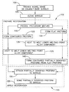
FIG. 1 is a block flow diagram of a preferred approach for practicing an
embodiment
of the method of the invention.
FIG. 2 is a fragmentary schematic front elevational view of a portion of a gas
turbine.
FIG. 3 is a cross-sectional view along line 3-3 of Figure 2 of a gas turbine
stationary
flowpath shroud assembly and its relation to a turbine blade.
FIG. 4 is a perspective view of a segment of the gas turbine stationary
flowpath
shroud.
FIG. 5 is a bottom view of the gas turbine stationary flowpath shroud.
FIG. 6 is a front view of the gas turbine stationary flowpath shroud.
FIG. 7 is an enlarged schematic side elevational view of the gas turbine
stationary
flowpath shroud during the restoration process.
4
CA 02581908 2013-06-25
163858 (13DV)
DETAILED DESCRIPTION OF THE INVENTION
FIG. 1 depicts in block diagram form embodiments of a method for repairing a
nickel-
base or cobalt-base superalloy turbine flowpath shroud. In practicing the
method, L'o.e
nickel-base or cobalt-base superalloy turbine flowpath shroud that has
previously
been in service is provided, step 100. FIGS. 2-7 depict the use of the method
in
relation to the gas turbine stationary flowpath shroud.
FIG. 2 presents a simplified depiction of the relevant portions of a gas
turbine 40,
illustrating only the components of interest. The gas turbine 40 includes a
turbine
disk 42 that is fixed to and rotates with a center shaft 44. A plurality of
turbine blades
46 extend radially outwardly from a periphery 48 of the turbine disk 42. A gas
turbine stationary flowpath shroud 50 forms a tunnel-like structure in which
the
turbine disk 42, the shaft 44, and the turbine blades 46 rotate. The gas
turbine
stationary flowpath shroud 50 is termed "stationary" and does not rotate as
the turbine
disk 42, the shaft 44, and the turbine blades 46 rotate. The stationary gas
turbine
stationary flowpath shroud 50 is to be distinguished from the rotating shrouds
that are
found near the tips of some types of gas turbine blades. The gas turbine
stationary
flowpath shroud 50 is formed by a series of curved stationary shroud segments
52 that
together define the cylindrical gas turbine stationary flowpath shroud 50. A
combustion gas flow 54 flowing from the combustors (not shown) of the gas
turbine
engine is perpendicular to the plane of the drawing of FIG. 2.
FIG. 3 illustrates the gas turbine stationary flowpath shroud 50 and one of
the
stationary shroud segments 52 in greater detail. Each stationary shroud
segment 52 is
supported on a shroud hanger structure 56. The gas turbine stationary flowpath
shroud 50 and the stationary shroud segment 52 have a flowpath surface 58 that
faces
but is spaced apart from a tip 60 of the turbine blade 46. In the operation of
the gas
turbine 40, it is important that the separation of the flowpath surface 58 and
the tip 60,
termed the clearance gap CG, be within specified tolerance limits. During
service,
both the flowpath surface 58 and the tip 60 are eroded, corroded, and oxidized
by the
hot combustion gas 54, and occasionally rubbed together with a consequent loss
of
material. The value of CG therefore increases over time, until it becomes so
large that
CA 02581908 2013-06-25
163858 (I3DV)
an unacceptable amount of the combustion gas flow 54 leaks between the
flowpath
surface 58 of the stationary flowpath shroud 50 and the tip 60, so that the
combustion
gas does not contact the turbine blade 46 and impart energy to it. The result
is the loss
of efficiency of the gas turbine 40.
FIG. 4 depicts the side opposite the flowpath surface 58. FIGS. 5-6 illustrate
the
bottom (FIG. 5) and front elevational (FIG. 6) views. The article such as the
gas
turbine stationary flowpath shroud 50 is preferably made of a nickel-base
superalloy
or a cobalt-base superalloy. As used herein, -nickel-base" means that the
composition
has more nickel present than any other element. The nickel-base superalloys
are of a
composition that is strengthened by the precipitation of gamma-prime phase or
a
related phase. In a preferred embodiment, the article comprises ReneTM N5
alloy, the
alloy having a nominal composition, in weight percent, of about 7.5 percent
cobalt,
about 7.0 percent chromium, about 1.5 percent molybdenum, about 5 percent
tungsten, about 3 percent rhenium. about 6.5 percent tantalum, about 6.2
percent
aluminum, about 0.15 percent hafnium, about 0.05 percent carbon, about 0.004
percent boron, about 0.01 percent yttrium, and balance nickel and incidental
impurities. As used herein, "cobalt-base" means that the composition has more
cobalt
present than any other element. In another preferred embodiment, the article
comprises MAR-M-509Tm alloy, the alloy having a composition comprising, in
weight percent, chromium in the range of about 23 percent to about 24.25
percent,
nickel in the range of about 9 percent to about 11 percent, tungsten in the
range of
about 6.5 percent to about 7.5 percent, tantalum in the range of about 3
percent to
about 4 percent, carbon in the range of about 0.55 percent to about 0.65
percent,
zirconium in the range of about 0.3 percent to about 0.5 percent, up to about
2 percent
iron, up to about 0.3 percent silicon, up to about 0.1 percent copper, up to
about 0.1
percent manganese, up to about 0.015 percent phosphorus, up to about 0.015
percent
sulfur, up to about 0.01 percent boron, and balance cobalt and incidental
impurities.
The shroud segment 52 that has previously been in service is cleaned to remove
dirt,
oxidation and corrosion products, and other foreign matter resulting from the
prior
service, step 105. The cleaning is preferably accomplished by fluoride ion
cleaning,
6
CA 02581908 2013-06-25
10.525J5 (1.51)V)
as described in U.S. Patent No. 4,098,450, issued July 4, 1978, entitled,
"SUPERALLOY ARTICLE CLEANING AND REPAIR METHOD," and assigned to
the assignee of the present invention
A restoration coating is prepared, step 110, for application, step 145, to the
pre-repair
flowpath surface 74, of the stationary shroud segment 52. The step 110 first
includes
providing a precursor mixture, step 115. The precursor mixture comprises a mix
of a
higher-melting-point alloy powder component, a lower-melting-point alloy
powder
component and a fugitive binder. Preferably the powder size of both the lower-
melting-point alloy powder and the higher-melting-point powder is about
¨140/+325
mesh, although other powder sizes may be used for particular applications. The
two
alloy components are prepared separately, and then mixed together with the
fugitive
binder, as such fugitive binder is known in the art, to make the precursor
mixture.
The two alloy powder components are mixed together in a preselected proportion
to
form the alloy mixture. A fugitive binder is then added to the alloy powder
mixture to
form the precursor mixture provided in step 115. The binder is preferably an
organic
material that holds the alloy powders together in a selected shape for initial
handling,
but later burns away during partial densification, step 135.
In one embodiment wherein the shroud 50 comprises a nickel-base superalloy,
the two
alloys in the precursor mixture are described in detail in U.S. Patent
6,982,123 entitled
"METHOD FOR REPAIR OF A NICKEL-BASE SUPERALLOY ARTICLE USING
A THERMALLY DENSIFIED COATING", which is assigned to the assignee of the
present invention. A preferred higher-melting-point alloy component for use
with the
nickel-base superalloy embodiment of shroud SO has a nominal composition, in
weight
percent, of about 3.1 percent cobalt, about 7.6 percent chromium, up to about
0.1
percent molybdenum, about 3.85 percent tungsten, up to about 0.02 percent
titanium,
about 1.65 percent rhenium, about 0.55 percent silicon, about 5.45 percent
tantalum,
about 7.8 percent aluminum, about 0.15 percent hafnium, about 0.02 percent
carbon,
7
CA 02581908 2013-06-25
163858 (13DV)
balance nickel and incidental impurities. In another preferred embodiment the
higher-
melting-point alloy component for use with the nickel-base superalloy
embodiment of
shroud 50 comprises, in weight percent, about 0.01 percent to about 0.03
percent
carbon, up to about 0.1 percent manganese, about 0.5 percent to about0.6
percent
silicon, up to about 0.01 percent phosphorus, up to about 0.004 percent
sulfur, about
7.4 percent to about 7.8 percent chromium, about 2.9 percent to about 3.3
percent
cobalt, up to about 0.1 percent molybdenum, about 3.7 percent to about 4.0
percent
tungsten, about 5.3 percent to about 5.6 percent tantalum, up to about 0.02
percent
titanium, about 7.6 percent to about 8.0 percent aluminum, about 1.5 percent
to about
1.8 percent rhenium, up to about 0.005 percent selenium, up to about 0.3
percent
platinum, about 0.01 percent to about 0.02 percent boron, up to about 0.03
percent
zirconium, about 0.12 to about 0.18 percent hafnium, up to about 0.1 percent
niobium,
up to about 0.1 percent vanadium, up to about 0.1 percent copper, up to about
0.2
percent iron, up to about 0.0035 percent magnesium, up to about 0.01 percent
oxygen,
up to about 0.01 percent nitrogen, balance nickel with incidental impurities.
In a
preferred embodiment, the lower-melting-point alloy component for use with the
nickel-base superalloy embodiment of shroud 50 comprises, in weight percent,
about
14.0 percent to about 16.0 percent cobalt, about 19.0 percent to about 21.0
percent
chromium, about 4.5 percent to about 5.5 percent aluminum, up to about 0.05
carbon,
about 7.7 percent to about 8.1 percent silicon, up to about 0.5 percent iron,
up to about
0.1 percent magnesium, balance nickel and incidental impurities. In a
preferred
embodiment, the alloy components of the precursor mixture for use with the
nickel-
base superalloy embodiment of shroud 50 comprise, in weight percent, about 79
percent of the higher-melting-point alloy component and balance the lower-
melting-
point alloy component.
In one embodiment wherein the shroud 50 comprises a nickel-base superalloy,
the
alloy components of the precursor mixture, combined, comprise no more than
about
15 weight percent chromium, preferably no more than about 12 weight percent
chromium, and most preferably about 10 weight percent chromium. In such an
embodiment, the alloy components of the precursor mixture, combined, comprise
no
more than about 0.01 percent yttrium, and preferably substantially no yttrium
(i.e., no
8
CA 02581908 2013-06-25
163858 (13DV)
more than about 0.001 percent). In another preferred embodiment, the alloy
components in the precursor mixture for use with the nickel-base superalloy
embodiment of shroud 50, combined, have a nominal composition, in weight
percent,
of about 10.2 percent chromium, about 5.6 percent cobalt, about 7.2 percent
aluminum, about 4.3 percent tantalum, about 1.3 percent rhenium, about 3.1
percent
tungsten, about 0.1 percent hafnium, about 2.1 percent silicon, substantially
no
yttrium, balance nickel and impurities.
In an alternate embodiment wherein the shroud 50 comprises a nickel-base
superalloy,
the two alloys in the precursor mixture are described in detail in U.S. Patent
No.
5,561.827, issued on October 1, 1996, and entitled "COATED NICKEL-BASE
SUPERALLOY AND POWDER AND METHOD USEFUL IN ITS
PREPARATION", which is assigned to the assignee of the present invention. A
preferred alternate higher-melting-point alloy component for use with the
nickel-base
superalloy embodiment of shroud 50 has a composition comprising, in weight
percent,
of about 10 percent to about 20 percent cobalt, about 14 percent to about 25
percent
chromium, about 2 percent to about 12 percent aluminum, from 0 to about 0.2
percent
yttrium, balance nickel and incidental impurities. A more preferred alternate
higher-
melting-point alloy component for use with the nickel-base superalloy
embodiment of
shroud 50 has a composition comprising, in weight percent, of about 14 percent
to
about 16 percent cobalt, about 19 percent to about 21 percent chromium, about
8.5
percent to about 9.5 percent aluminum, about 0.05 percent to about 0.15
percent
yttrium, up to about 0.02 percent boron, up to about 0.05 percent carbon, up
to about
0.500 percent iron, up to about 0.0075 percent selenium, up to about 0.1
percent
silicon, up to about 0.010 percent phosphorus, up to about 0.010 percent
copper, up to
about 0.10 magnesium, and balance nickel. A preferred alternate lower-melting-
point
alloy component for use with the nickel-base superalloy embodiment of shroud
50 has
a composition comprising, in weight percent, of about 10 percent to about 20
percent
cobalt, about 14 percent to about 25 percent chromium, about 2 to about 12
percent
aluminum, about 0.001 percent to about 3 percent boron, about 2 percent to
about 12
percent silicon, balance nickel and incidental impurities. A more preferred
alternate
9
CA 02581908 2013-06-25
163858 (13DV)
=
lower-melting-point alloy component for use with the nickel-base superalloy
embodiment of shroud 50 comprises, in weight percent, about 14 percent to
about 16
percent cobalt, about 19 percent to about 21 percent chromium, about 4.5 to
about 5.5
percent aluminum, about 8 percent silicon, up to about 0.05 percent boron, up
to about
0.05 percent carbon, up to about 0.500 percent iron, about 0.0075 percent
selenium,
up to about 0.010 percent phosphorous, up to about 0.010 percent copper, up to
about
0.10 percent magnesium, balance nickel. In an alternate preferred embodiment,
the
alloy components of the precursor mixture for use with the nickel-base
superalloy
embodiment of shroud 50, combined, comprise, in weight percent, about 60
percent to
about 75 percent of the higher-melting-point alloy component and balance the
lower-
melting-point alloy component. In a more preferred embodiment, the alloy
mixture
for use with the nickel-base superalloy embodiment of shroud 50 comprises, in
weight
percent, about 68.5 percent of the higher-melting-point alloy component and
balance
the lower-melting-point alloy component.
In an alternate embodiment the alloy components of the precursor mixture,
combined,
for use with the nickel-base superalloy embodiment of shroud 50 comprise, in
weight
percent, about 10 percent to about 20 percent cobalt, about 14 percent to
about 25
percent chromium, about 2 percent to about 12 percent aluminum, from 0 to
about 0.2
percent yttrium, about 0.001 percent to about 3 percent boron, about 1 percent
to
about 10 percent silicon, and balance nickel and incidental impurities.
In another alternate embodiment wherein the shroud 50 comprises a cobalt-base
superalloy, the two alloys in the precursor mixture are described in detail in
U.S.
Patent No. 4,842,953, issued on June 27, 1989, and entitled "ABRADABLE
ARTICLE AND POWDER AND METHOD FOR MAKING," which is assigned to
the assignee of the present invention, and described in detail in U.S. Patent
No.4,937,042, issued on June 26, 1990, and entitled "METHOD FOR MAKING AN
ABRADABLE ARTICLE," which is assigned to the assignee of the present
invention. Another alternate preferred higher-melting-point alloy component
for use
with the cobalt-base superalloy embodiment of shroud 50 has
CA 02581908 2013-06-25
163858 (13DV)
a composition comprising, in weight percent, about 16.8 percent to about 32.7
percent
nickel, about 21.5 percent to about 24.9 percent chromium, about 8 percent to
about
9.9 percent aluminum, about 0.045 percent to about 0.13 percent yttrium,
balance
cobalt and incidental impurities, and further characterized as having
substantially no
silicon. Another alternate more preferred higher-melting-point alloy component
for
use with the cobalt-base superalloy embodiment of shroud 50 has a composition
comprising, in weight percent, about 30.5 percent to about 32.5 percent
nickel, about
21.5 percent to about 22.5 percent chromium, about 8 percent to about 9
percent
aluminum, about 0.045 percent to about 0.095 percent yttrium, up to about 0.5
percent
iron, up to about 0.011 percent carbon, up to about 0.005 percent sulfur, up
to about
0.010 percent phosphorus, up to about 0.0175 percent oxygen, up to about 0.015
percent nitrogen, balance cobalt and incidental impurities and further
characterized as
having substantially no silicon. Another alternate preferred lower-melting-
point alloy
component for use with the cobalt-base superalloy embodiment of shroud 50 has
a
composition comprising, in weight percent, about 38 percent to about 53.1
percent
nickel, about 10 percent to about 30 percent chromium, about 8 percent to
about 12
percent silicon, about 1.5 percent to about 4 percent aluminum, balance cobalt
and
incidental impurities, and further characterized as having substantially no
yttrium.
Another alternate more preferred lower-melting-point alloy component for use
with
the cobalt-base superalloy embodiment of shroud 50 has a composition
comprising, in
weight percent, about 38 percent to about 40 percent nickel, about 21.5
percent to
about 22.5 percent chromium, about 3.4 percent to about 4.4 percent aluminum,
about
9.8 percent to about 10.2 percent silicon, up to about 0.50 percent iron, up
to about
0.011 percent carbon, up to about 0.005 percent sulfur, up to about 0.010
percent
phosphorus, up to about 0.0175 percent oxygen, up to about 0.015 percent
nitrogen,
balance cobalt and incidental impurities, and further characterized as having
substantially no yttrium. In an alternate preferred embodiment, the alloy
components
of the precursor mixture, combined, for use with the cobalt-base superalloy
embodiment of shroud 50 comprise, in weight percent, about 50 percent to about
70
percent of the higher-melting-point alloy component and balance the lower-
melting-
point alloy component.
11
CA 02581908 2013-06-25
163858 (13DV)
In another alternate embodiment the alloy components of the precursor mixture,
combined, for use with the cobalt-base superalloy embodiment of shroud 50
comprise,
in weight percent, about 10 percent to about 35 percent chromium, about 4
percent to
about 10 percent aluminum, up to about 0.09 percent yttrium, about 2 percent
to about
6 percent silicon, balance cobalt and incidental impurities, the coating
further being
characterized by the substantial absence of boron.
In one embodiment the next step 120 after providing the precursor mixture 115
is
forming the precursor mixture into a thin mildly curved preform that conforms
to the
shape of the mildly curved pre-repair flowpath surface 74 and has a thickness
in the
range of about 0.080 inch to about 0.120 inch. The mildly curved preform may
be
formed by tape casing, pressing, injection molding, or any other operable
method. A
description of binders used for the pressing process and the pressing process
may be
found in U.S. Patent No. 5,705,281, entitled "COATED NICKEL-BASE
SUPERALLOY ARTILCE AND POWDER AND METHOD USEFUL IN ITS
PREPARATION". It is not necessary that the preform have little porosity as it
is later
partially densified by brazing, reducing the porosity. For the injection
molding
method, plastic binders are used. After the mildly curved preform is formed in
step
120, the next step 125 is partially densifying the preform by heating the
preform in a
vacuum furnace at a temperature above the melting point of the lower-melting-
point
alloy component for a time sufficient to form a partially densified preform.
The step
of heating 125 takes place when the preform is on a mildly curved plate so
that the
preform retains its mildly curved shape. The mildly curved plate preferably
comprises a material selected from the group consisting of alumina, zirconia,
and
ceramic felt, although any functional material as known in the art may be
used. The
partial densification preferably takes place at a temperature below the
melting point of
the higher-melting-point alloy. The partial densification preferably takes
place at a
temperature in the range of about 1177 C (2150 F) to about 1246 C (2275 F) for
a
time in the range of about 0.25 hours to about 4 hours. The partial
densification more
preferably takes place at a temperature in the range of about 1232 C (2250 F)
to
about 1243 C (2270 F) for a time of about 2 hours.
12
CA 02581908 2013-06-25
163858 (13DV)
In an alternate embodiment the next step 130 after the step of providing the
precursor
mixture 115 is forming a thin flat preform. The flat preform may be formed by
tape
casing, pressing, injection molding, or any other operable method. It is not
necessary
that the preform have little porosity as it is later partially densified by
brazing,
reducing the porosity. For the injection molding method, plastic binders are
used.
In this alternate embodiment, after the flat preform is formed in step 130,
the next
step 135 is partially densifying the preform by heating the preform in a
vacuum
furnace on a flat plate at a temperature above the melting point of the lower-
melting-
point alloy component for a time sufficient to form a partially densified
preform. The
flat plate preferably comprises a material selected from the group consisting
of
alumina, zirconia, and ceramic felt, although any functional material as known
in the
art may be used. The partial densification preferably takes place at a
temperature
below the melting point of the higher-melting-point alloy. The partial
densification
preferably takes place at a temperature in the range of about 1177 C (2150 F)
to
about 1246 C (2275 F) for a time in the range of about 0.25 hours to about 4
hours.
The partial densification more preferably takes place at a temperature in the
range of
about 1232 C (2250 F) to about 1243 C (2270 F) for a time of about 2 hours.
The next step 140 in this alternate embodiment is forming a mildly curved
partially
densified preform from the flat densitied perform formed in step 135. This may
be
accomplished by any means known in the art, such as mechanically working the
flat
partially densified preform.
In either case, once the mildly curved partially densified preform is formed,
the next
step 145 is applying the restoration. The first step 150 of applying the
restoration is
attaching the mildly curved partially densified preform to the pre-repair
flowpath
surface 74 of the shroud 50. The preform may be attached by any means known in
the art, such as by weighing down the preform, using an adhesive, or spot
welding the
preform to the pre-repair flowpath surface 74.
The next step 155 is bonding the partially densified preform to the shroud 50
by
heating the preform and the shroud 50 in a vacuum furnace to a temperature in
the
range of about 1232 C (2250 F) to about 1288 C (2350 F) for a period of time
in the
13
CA 02581908 2013-06-25
- - - -
163858 (13DV)
range of about 20 minutes to about 2 hours. The step of bonding 155 preferably
takes
place at a temperature of from about 1249 C (2280 F) to about 1274 C (2325 F)
for
about 2 hours.
As shown in FIG. 7, the exposed surface of the coating 72 is the new, repaired
flowpath surface 58. The restoration coating 72 may be applied in any operable
thickness t, that returns the dimension of the shroud 50 to its desired
values, but is
preferably is applied to a thickness of from about 0.080 to about 0.120 inch.
The
restoration coating although it may be applied in larger or smaller
thicknesses, for
example from about 0.04 inch to about 0.160 inch. The porosity of the coating
is in
the range of about 0.3 % to about 3.0%.
After processing, the shroud 50 comprises a nickel-base or cobalt base
superalloy
shroud 50 that has previously been in service, and a restoration partially
densified
preform applied and diffusion metallurgically bonded to the pre-repair
flowpath
surface 74 of the shroud segment 52, with the partially densified preform
forming a
restoration coating 72. The porosity of the restoration coating 72 is
preferably in the
range of about 0.3 percent to about 3.0 percent.
Optionally, an environmental coating may be applied to protect portions of the
shroud
as known in the art. The environmental coating is typically a diffusion
aluminide
applied by vapor phase aluminiding (VPA), a process known in the art. Any
portion
of the environmental coating that deposits on the flowpath surface 58 is
machined
away prior to operation of the engine.
While there have been described herein what are considered to be preferred and
exemplary embodiments of the present invention, other modifications of these
embodiments falling within the invention described herein shall be apparent to
those
skilled in the art.
14