Note: Descriptions are shown in the official language in which they were submitted.
CA 02581977 2007-03-27
WO 2006/037008 PCT/US2005/034731
1
COMPOSITES CONTAINING CROSSLINKABLE THERMOPLASTIC
AND TPV SHOW LAYER
[0001] The present application is a continuation-in-part application of U.S.
Serial
No. 09/912,099, filed July 24, 2001.
BACKGROUND
[0002] The present exemplary embodiments relate to a process for forming
molded or extruded composites and the products formed thereby, particularly
automobile weather strips. They finds particular application in conjunction
with
vehicle weather strip composites comprised of an elastomeric polymer and a
show
layer including a thermoplastic vulcanizate and a crosslinked thermoplastic
polyolefin, and will be described with particular reference thereto. However,
it is to
be appreciated that the present exemplary embodiments are also amenable to
other
like applications.
[0003] It is common in the motor vehicle industry to fashion decorative
abrasion resistant sections for various parts of an automobile by extruding or
molding such sections from certain thermosetting polymeric materials. Examples
of
typical abrasion resistant sections manufactured by such a process include
colored
weather strips. These weather strips are mounted on an automobile door surface
and along the perimeter of automobile doors to provide a seal between the door
and
the automobile body as well as to protect both the door and exterior objects
when
they come in contact with each other. Weather strips are typically molded or
extruded and attached to a vehicle by an adhesive tape or by mechanical means
such as by crimping or the use of fasteners.
[0004] Various thermoset elastomeric rubber materials, such as ethylene
propylene diene terpolymer (EPDM), styrene-butadiene copolymer (SBR) and
chloroprene rubbers have been commonly used to form these weather strips.
These
materials are favored by manufacturers because they are relatively inexpensive
compared to thermoplastics and generally exhibit both the desired flexibility
necessary for providing an effective seal and acceptable weatherability
properties.
However, these elastomers typically lack the low-friction, abrasion
resistance, and
CA 02581977 2007-03-27
WO 2006/037008 PCT/US2005/034731
-2-
weatherability that is necessary at the point of contact with the exterior for
extended
life of the weather strips. In addition, it is difficult to impart desirable
surface color
and gloss to such materials.
[0005] Manufacturers have therefore attempted a variety of approaches to
improve the wear resistance, aesthetics and other properties of elastomeric
sealing
sections. One strategy for weather strips has been to apply a second layer of
low
friction polymer to selected surfaces of the elastomeric weather strip,
particularly
along an area that is exposed to the exterior. Incorporated within the second
layer
can be various pigments or dyes such that the surface of the weather strip
matches
the color of the automobile.
[0006] Depending on the composition of the main body of the weather strip,
this
second layer is often formed from polyvinyl chloride (PVC) or an uncured non-
polar
thermoplastic elastomer, such as polypropylene or polyethylene. These second
layers are usually applied directly to the weather strip surface by lamination
or as a
solvent-based spray, or after an application of a primer or adhesive layer to
the
elastomer. However, these methods are not completely satisfactory. In addition
to
longer processing time and added material cost, it is difficult to obtain a
satisfactory
bond between the elastomer and the surface coating. Sprayed on coatings are
prone to cracking while an adhered layer is susceptible to peeling.
[0007] Another method that manufacturers have used to adhere the second layer
to the extruded weather strip is to cohesively bond a layer of wear resistant
thermoplastic to the weather strip. Several techniques have been developed to
accomplish this. According to one method, the elastomer rubber and the second
layer are co-extruded. The resulting composite is then passed through an oven
in
which the elastomer rubber is cured and the interface between the second layer
and
the rubber is heated to such a degree that the second layer partially melts,
causing it
to adhesively bond with the rubber. Alternately, the rubber is extruded first
and
passes through an oven in which it is at least partially cured. A molten
thermoplastic
is then extruded onto the vulcanized rubber. The residual heat of the rubber
as it
emerges from the oven promotes interdiffusion of the two layers at the
interface
between the two, forming a bond between the two materials.
[0008] Due in part to the uncrosslinked nature of the thermoplastic, however,
it is
difficult to control exactly the degree of melting that the second layer
undergoes in
this technique. If the second layer melts too much, the abrasion resistance it
affords
CA 02581977 2007-03-27
WO 2006/037008 PCT/US2005/034731
-3-
may be compromised and its aesthetic appeal diminished. Thus, there is a need
for
a new vehicle weather strip composite that overcomes the deficiencies and
limitations of the prior art.
BRIEF SUMMARY OF THE INVENTION
[0009] In a first embodiment, there is provided a process for forming a
composite
automobile weather strip including a main body member of elastomeric polymer
and
an abrasion resistant decorative layer, the abrasion resistant decorative
layer
including a blend of a crosslinkable polyolefin and a thermoplastic
vulcanizate.
[0010] The use of a crosslinkable TPO allows a manufacturer to maintain the
desirable qualities associated with thermoplastics while affording greater
control of
melting and alleviating other processing concerns. The crosslinkable
polyolefin may
contain grafted silane functional groups. In the presence of moisture, water
hydrolyzes the silane. Under the action of a catalyst, the resulting silanol
groups
then condense to form intermolecular crosslinking sites. The thermoset
elastomer
rubber may be cured by sulfur or peroxide agents.
[0011] In a second embodiment, there is provided a wear resistant composite
suitable for use as a vehicle weather strip including an abrasion resistant
decorative
layer, wherein the abrasion resistant decorative layer includes a
crosslinkable olefin
polymer and a thermoplastic vulcanizate, bonded to and disposed immediately
adjacent an at least partially crosslinked elastomer polymer main body member.
[0012] The versatility of the abrasion resistant decorative layer allows it to
be
applied to the elastomer member in several ways. In a first preferred
technique, the
olefinic polymer/TPV blend is co-extruded with an uncured thermoset elastomer
rubber main body member and then exposed to water to crosslink the olefinic
polymer. The resultant composite is then passed through an oven to vulcanize
the
thermoset elastomer rubber main body member. In a second preferred technique,
the olefinic polymer/TPV blend is step extruded onto a previously cured or
partially
cured thermoset elastomer rubber main body member. The crosslinkable olefinic
polymer in the blend is then crosslinked by immersion in a water bath, or
otherwise
exposed to moisture. In a third preferred technique, the olefinic polymer/TPV
blend
is extruded into a sheet or tape form and laminated onto a previously cured o
r
partially cured thermoset elastomer rubber main body member. The resulting
composite is then subjected to a water bath, or otherwise exposed to moisture,
to
CA 02581977 2007-03-27
WO 2006/037008 PCT/US2005/034731
-4-
crosslink the grafted silane groups in the olefinic polymer. Alternately, the
elastomer
member and/or the olefinic polymer/TPV blend are molded heat bonded to each
other.
[0013] While all the techniques produce acceptable results, if o(efinic
polymer/TPV blend is applied to the elastomer main body prior to the curing of
the
main body member, the olefinic polymer should preferably be crosslinked before
the
elastomer main body member is cured. This is to ensure that the decorative
layer
does not melt excessively during the subsequent heating.
BRIEF DESCRIPTION OF THE DRAWINGS
[0014] Figure 1 is a cross section of a preferred embodiment weather strip for
a
vehicle in accordance with the present invention.
[0015] Figure 2 is a depiction of a first preferred technique of the present
invention for manufacturing a composite extrusion suitable for use as weather
strip
for a vehicle.
[0016] Figure 3 is a depiction of an alternative preferred technique of the
present
invention for manufacturing a composite extrusion suitable for use as a
weather strip
for a vehicle.
[0017] Figure 4 is a depiction of an another alternative preferred technique
of the
present invention for manufacturing a composite extrusion suitable for use as
a
weather strip for a vehicle.
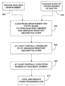
[0018] Figure 5 is a flowchart depicting the main processing steps in the
first
preferred technique of the invention detailed in figure 2.
[0019] Figure 6 is a flowchart depicting the main processing steps in the
second
preferred technique of the invention detailed in figure 3.
[0020] Figure 7 is a flowchart depicting the main processing steps in the
third
preferred technique of the invention detailed in figure 4.
DETAILED DESCRIPTION OF THE PREFERRED EMBODIMENTS
[0021] The present invention provides a variety of sealing strips, weather
strips,
glass run channels, etc. for vehicles. As used herein, the term "weather
strip" is
used to refer broadly to any such strips conventionally used in automobiles
and
other vehicles. Briefly, the weather strips preferably comprise at least two
components, each formed from particular materials and having a unique cross-
CA 02581977 2007-03-27
WO 2006/037008 PCT/US2005/034731
-5-
sectional configuration. A preferred weather strip comprises an elastomer
polymer
main body member having any of several shapes convenfiional in the art.
[0022] The weather strip also comprises an abrasion resistant decorative layer
comprised of an abrasion resistant material disposed on the outwardly facing
surface of the main body member. As explained in greater detail below, the
layer
preferably comprises a moisture crossiinkable olefin polymer and a
thermoplastic
vulcanizate.
[0023] With reference to figure 1, a cross-section of a preferred embodiment
weather strip for a vehicle in accordance with the present invention is shown.
The
preferred embodiment weather strip is comprised of a main body member 2, made
from one or more of a number of elastomeric polymers known in the art to be
suitable for weather strip applications, and an abrasion resistant decorative
layer 4.
[0024] The elastomeric polymers suitable for use in the main body member
include any conventional material used for such purposes. Thus, exemplary
materials include elastomeric rubbers, as well as thermoplastic vulcanizates
(TPV's)
and other elastomeric polymers.
[0025] Suitable elastomeric rubber compositions for use in the main body
member include, but are not limited to, ethylene-a-olefin-non-conjugated diene
rubbers (EODM), styrene-butadiene rubbers (SBR), acrylonitrile-butadiene
rubber,
natural or synthetic isoprene rubber and chloroprene rubber. EODM rubbers are
preferred due to their oxygen, ozone and weather resistance. Suitable a-
olefins
include, but not limited to, propylene, 1-butene, 1-pentene, 1-hexene, 1-
octene and
1-decene. A preferred a-olefin is propylene. A preferred group of EODM
compounds suitable for the present invention are ethylene-propylene-diene
terpolymers (EPDM). Suitable non-conjugated dienes include, but not limited
to,
1,4-hexadiene, d icyclo pentad iene and 5-ethylidene-2-norbornene. A preferred
EODM for the main body member of the weather strip of the present invention is
ethylene-propylene-ethylidene-norbornene terpolymer or ethylene-propylene-
dicyclopentadiene terpolymer. Various grades of elastomer thermoset rubber may
be used in the invention including dense elastomers and less dense, sponge
elastomers.
[0026] The elastomer of the main body member can further include various
additives known in the art in such concentrations that do not adversely affect
the
properties of the compound. Such additives include, but are not limited to,
CA 02581977 2007-03-27
WO 2006/037008 PCT/US2005/034731
-6-
vulcanization agents, carbon black, lubricants, plasticizers, fillers, slip
agents,
processing oils and antioxidants. These additives are added to the elastomer
prior
to formation of the main body member.
[0027] In one preferred embodiment (figure 1), the main body member 2 is
formed having a hollow tube 6 joined along its longitudinal axis at a region 8
on its
outer circumference to a tangential wall 10. Attached to one end of the
tangential
wall is a retention spur 12. Attached to an opposite end of the tangential
wall is a
second wall 14. The second wall 14 is substantially perpendicular to the
tangential
wall 10 at the junction between them, but gently curls back toward the
tangential
wall as the second wall 14 extends from the tangential wall 10. The second
wall 14
terminates at and defines its distal end 16 as shown in figure 1.
Approximately
midway between the junction of the tangential wall 10 and the second wall 14,
and
the distal end 16 of the second wall 14, a third wall 18 substantially
parallel to the
tangential wall 10 extends from the second wall 14. Together, the tangential
wall
10, the second wall 14 and the third wall 18 define an interior chamber 20.
Projecting from the tangential wall 10 on an opposite side from the hollow
tube 6 are
a plurality of sealing lips 22 that extend inward and upward therefrom toward
the
interior chamber 20. Attached to a distal end 24 of the third wall 18 and
projecting
inward and upward therefrom toward the interior chamber 20 is a large sealing
lip
26. Depending on the function of the weatherstrip, the make of the automobile,
the
shape of the chassis and doorframe, many alternative embodiments are also
contemplated.
[0028] Irrespective of the exact shape of the main body member, applied to an
exteriorly directed surface (not numbered) of the second wall 14 of the main
body
member 2 is the abrasion resistant decorative layer 4 comprised of a
crosslinkable
olefin polymer and a thermoplastic vulcanizate. This abrasion resistant
decorative
layer 4 is applied along the main body member at those areas that contact the
door,
vehicle frame or exterior objects (not pictured) to improve the wear
resistance and
aesthetics of the weather strip at those locations. In addition, the abrasion
resistant
decorative layer 4 may be applied to other areas of the main body member 2
that
contact these objects for added protection and scuff resistance, such as the
various
surfaces of the main body member (not numbered) that are exposed to and face
the
interior chamber 20.
CA 02581977 2007-03-27
WO 2006/037008 PCT/US2005/034731
-7-
[0029] Thermoplastic vulcanizates (TPV's) are polyolefinic matrices,
preferably
crystalline, through which thermoset elastomers are generally uniformly
distributed.
Examples of thermoplastic vulcanizates include EPM and EPDM thermoset
materials distributed in a crystalline polypropylene matrix. Any conventional
TPV
having the desired weatherability, flexibility and strength may be used in the
present
invention. Although not intended to be limiting, examples of suitable TPVs for
use in
the present invention include those prepared by blending an olefinic
thermoplastic
and either an ethylene copolymer or terpolymer, such as disclosed in U.S.
Patent
No. 4,990,566 to Hert, or a nitrile rubber, such as disclosed in U.S. Patent
No.
4,591,615 to Aldred et al, the disclosure of both of which are incorporated
herein by
reference.
[0030] Commercial TPV's are typically based on vulcanized rubbers in which a
phenolic resin, sulfur or peroxide cure system is used to vulcanize, that is
crosslink,
a diene (or more generally, a polyene) copolymer rubber by way of dynamic
vulcanization, which is a process in which the rubber is crosslinked while
mixing
(typically vigorously), in a thermoplastic matrix. Although any cure system is
contemplated by the present embodiments, sulfur is typically preferred over
peroxide free radical or a phenolic resin cure systems because peroxide may
degrade and/or crosslink the polypropylene or polyethylene thermoplastic as
well as
the rubber. This is in turn limits the extent of rubber crosslinking that can
occur
before the entire mixture degrades or crosslinks and is no longer
thermoplastic,
while phenolic cure systems may cause a yellowish tint to the final product.
[0031] Two examples of preferred commercial TPV's are SANTOPRENE
thermoplastic rubber, which is manufactured by Advanced ElasfiomerSystems and
SARLINK , available from DSM Elastomers, both of which are a mixture of
crosslinked EPDM particles in a crystalline polypropylene matrix. These
materials
have found utility in many applications which previously used vulcanized
rubber, e.g.
hose, gaskets, and the like. TPV's are noted for their processability as
thermoplastics while retaining the excellent resilience and compression set
properties of vulcanized rubbers.
[0032] A preferred method of preparing a thermoplastic vulcanizate known by
those skilled in the art is to form an admixture of non-crosslinked
elastomeric
polymer and polyolefin resin and curing agent. The admixture is then
masticated at
a vulcanization temperature. Preferably the non-crosslinked polymer and
polyolefin
CA 02581977 2007-03-27
WO 2006/037008 PCT/US2005/034731
-8-
are intimately mixed before a curing agent is added. When prepared in a
conventional mixing apparatus such as a multiple-roll mill, Banbury or
Brabender
mixer or mixing extruder, this is known as a "two-pass" cycle. Additional
additives
may be added, including, but not limited to those fillers, fire retardants,
stabilizers,
pigments and antioxidants described above with respect to the TPO layer.
[0033] Various fillers and processing materials as well as other components
may
be added to the TPV used in the present invention. Non-limiting examples of
such
fillers include carbon black, calcium carbonate, clay, silica, and the like.
With
respect to processing materials, various processing oils, waxes and the like
intended to improve the processing of the material may be included in any
concentration that does not significantly detract from the properties of the
TPO.
[0034] The polymer may also be formulated with stabilizers, pigments and
antioxidants to obtain the appropriate weathering properties. In addition,
fiame
retardant fillers such as aluminum trihydrate (ATH), magnesium trioxide,
calcium
carbonate, mica, talc, or glass may be added. In one embodiment, filler levels
can
range from 0 to about 30% by weight.
[0035] A typical TPV is a melt blend or reactor blend of a polyolefin plastic,
typically a propylene polymer, with a crosslinked olefin copolymer elastomer
(OCE),
typically an ethylene-propylene rubber (EPM) or an ethylene-propylene-diene
rubber
(EPDM). In those TPV's made from EPDM, the diene monomer utilized in forming
the EPDM terpolymer is preferably a non-conjugated diene. Illustrative
examples of
non-conjugated dienes which may be employed are dicyclopentadiene,
alkyldicyciopentadiene, 1,4-pentadiene, 1,4-hexadiene, 1,5-hexadiene, 1,4-
heptadiene, 2-methyl-1,5-hexadiene, cyclooctadiene, 1,4-octadiene, 1,7-
octadiene,
5-ethylidene-2-norbornene, 5-n-propylidene-2-norbornene, 5-(2-methyl-2-
butenyl)-2-
norbornene and the like.
[0036] As explained in greater detail herein, in the final composite
extrusion,
such as incorporated into a door or window assembly, the at least two
polymeric
components making up the abrasion resistant decorative layer are. both at
least
partially crosslinked (the elastomer rubber in the TPV and the crosslinkable
olefin
polymer). Thus, although much of the description herein refers to the abrasion
resistant decorative layer as comprising crosslinkable polymeric materials (as
noted
above), it will be understood that in its preferred final manufactured form,
the
CA 02581977 2007-03-27
WO 2006/037008 PCT/US2005/034731
-9-
composite extrusion of the present invention utilizes an abrasion resistant
decorative
layer that comprises at least partially crosslinked materials.
[0037] The second component of the abrasion resistant decorative layer 4 is a
crosslinkable olefin polymer. This may include homopolymers, olefin copolymers
(copolymers of a polyolefin with another polyolefin or other polymer), or
blends of
such polymers. In a preferred embodiment, the crosslinkable olefin polymer is
a
crosslinkable olefinic homopolymer, particularly polyethylene. Preferred
crosslinkable olefinic homopolymers are those that can be crosslinked by
silane
grafting. Electron beam radiation crosslinking is not preferred because of its
expense. Likewise, peroxide crosslinking is not preferred because of the
processing
concerns that it entails. However, it is contemplated that the present
invention
weather strip and related methods could utilize such techniques for
crosslinking. A
preferred crosslinkable olefin polymer is a silane-grafted polyethylene, and
this will
be used as an example in the present discussion.
[0038] Other suitable olefinic homopolymers for use with the TPV in the
abrasion
resistant decorative layer include silahe grafted polypropylene, and higher
olefin
homopolymers. The homopolymers can be made via a variety of polymerization
systems (including metallocene catalyzed and conventional catalysis systems)
and
have a range of molecular weights and other characteristics. In one preferred
embodiment, the homopolymer is a polyethylene having a Mn of from about 20,000
to 100,000, a MW of from about 50,000 to 200,000 and a molecular weight
distribution of from about 2.5 to 4Ø
[0039] One stage silane crosslinking involves the extrusion of a direct
mixture of
the polymer resin with a silane concentrate that includes a catalyst. The
extrudate is
subsequently crosslinked in the presence of water. In two-stage crosslinking,
silane
is first grafted to the polymer molecular chains according to known reactions
to yield
a silane grafted copolymer.
Polymer Backbone
RQ Si R
I R Silane graft
CA 02581977 2007-03-27
WO 2006/037008 PCT/US2005/034731
-10-
[0040] Subsequently, the silane-grafted copolymer is mixed with a silanol
condensation catalyst and then exposed to water to effect crosslinking of the
copolymer in a two step reaction. First, the water hydrolyzes the silane to
produce a
silanol. The silanol then condenses to form intermolecular, irreversible Si-O-
Si
crosslink sites.
Step 1
iti-, -nj~r
RO-Si-OR + H2 . HO-Si-OH
i-OH
OR OH
Step 2
HO- i-OH
~
Catalyst
HO-Si-OH
+ HO-Si-OH I HO-Si-OH
pH OH
[0041] The amount of crosslinked silane groups, and thus the final polymer
properties, can be regulated by controlling the production process, including
the
amount of catalyst used. A gel test (ASTM D2765) is used to determine the
amount
of crosslinking. In one embodiment and prior to being crosslinked, the
polyethylene,
or other olefin polymer preferably has a melt flow index determined according
to
ASTM D-1238 of about 0.5-20 g/10 min at 190 C and 2.16 kg load and a Shore A
hard ness of about 50-90. Most preferably, it exhibits a melt flow index of
about 0.7-
1.2g/10 min at 190 C with a 2.16 kg load, a Shore A hardness of about 70 and a
density of about 0.8 - 1.2 g/cm3.
[0042] The catalyst can be any of a wide variety of materials that are known
to
funetion as silanol condensation catalysts including many metal carboxylates
and
fatty acids. A preferred catalyst is dibutyltindilaurate.
[0043] In one embodiment, the abrasion resistant decorative layer preferably
includes about 75% to about 87% by weight of the TPV and from about 9% to
about
CA 02581977 2007-03-27
WO 2006/037008 PCT/US2005/034731
-11-
15% by weight of the crosslinkable olefin polymer. The abrasion resistant
decorative layer can also contain conventional additives including, but not
limited to,
organic and inorganic fillers, plasticizers, slip agents, UV stabilizers,
antioxidants
and, as previously mentioned, coloring agents in an amount up to about 30%,
more
preferably about 2-5%.
[0044] In one embodiment, a slip agent or other lubricant is added to the
blend
prior to processing. Any conventional slip agent material may be utilized.
Preferred
slip agents include polysiloxane slip agents known in the art. The use of such
slip
agents reduces the coefficient of friction of the resulting show layers such
that the
use of a separate slip coating on the surface of the finished product is not
necessary, resulting in reduced labor and expense. Such slip agents may
generally
be present in an amount of from about 0.1-20.0% by weight, more typically from
about 2.0-8.0%.
[0045] In addition, the use of a coloring agent in the blend allows one to
customize the color of the surface of the final weather strip to match or
complement
the color of the vehicle or its interior. The ability of the blend to retain
color and
gioss is superior to that of conventional elastomeric rubbers.
[0046] The TPV and the crosslinkable olefin polymer are preferably pre-blended
priorto depositing on the elastomer main body member. Thus, in one embodiment,
the TPV and crosslinkable olefin polymer may be pre-blended and extruded into
pelletized form. Preferably, the material is dried to eliminate moisture that
may start
the crosslinking process of the olefin polymer. The pre-blended mixture may
then
be mixed with a crosslinking catalyst in a suitable amount (for example 2-7%
by
weight) prior to its extrusion onto the elastomer main body member.
[0047] Subsequently, the abrasion resistant decorative layer 4 can be applied
to
the main body rnember 2-in one of several different ways. For ease of
description,
the different processes will be described utilizing a two stage crosslinkable,
silane-
grafted polyethylene homopolymer biended with a TPV as the abrasion resistant
decorative layer 4 and EPDM as the thermoset elastomer rubber main body
member 2. However, the present invention contemplates the use of other
crosslinkable olefin polymers in the abrasion resistant decorative layer 4 and
other
elastomers in the main body member 2.
[0048] As noted above, the elastomer main body member and abrasion resistant
decorative layer may be extruded, molded, or otherwise processed in a variety
of
CA 02581977 2007-03-27
WO 2006/037008 PCT/US2005/034731
-12-
ways known in the art. Several different extrusion methods are described
below.
These are not intended to be limiting however, and other methods of producing
the
final composites are also contemplated, such as, e.g., compression or
injection
molding.
[0049] The present invention provides a first preferred technique for
producing a
composite extrusion by co-extruding an uncured EPDM main body member, such as
item 2 in figure 1, and an uncrosslinked silane-grafted polyethylene/TPV
abrasion
resistant decorative layer, such as item 4 in figure 1, through an extrusion
die. With
reference to figure 5, a schematic diagram is shown outlining the preferred
processing steps in this first preferred technique. Briefly, an uncured EPDM
rubber
and crosslinkable polyethylene/TPV blend are provided 500, 502. The EPDM
rubber and the PE/TPV blend are coextruded 504 to form a main body member and
an abrasion resistant decorative layer, respectively. Subsequently, the
polyethylene
in the blend is at least partially crosslinked 506. The EPDM rubber of the
main body
member is then at least partially cu red 508 prior to removal of the assembly
from the
processing line 510.
[0050] With greater detail and with further reference to figure 2, a first
extruder 50
for processing a blend of a silane-grafted crosslinkable polyethylene and a
TPV, a
second extruder 52 for processing a sponge EPDM and a third extruder 54 for
processing a dense EPDM are placed in communication with an extrusion die 56.
The term "sponge EPDM" refers to an EPDM that contains biowing agents. The
term "dense EPDM" refers to an EPDM that does not contain any blowing agents.
For ease of description, the production process will be described using the
dense
extruder 54, although in actual practice both are typically used concurrently,
depending on the application. I n order to ensure sufficient flow of the EPDM
compound for subsequent extrusion, the EPDM extruder 54 is preferably
maintained
at a temperature of from about 70 C to about 85 C. For the same reason, the
PE/TPV extruder 50 is preferably maintained at about 130 C to about 210 C. The
extrusion die 56 is preferably maintained at about 110 C on an EPDM side 58
and
from about 200 C to about 260 C on an PE/TPV side 60. Insulation (not shown)
between the two sides of the extrusion die allows forfihis disparity in
temperatures to
be more easily achieved. For a dense EPDM, the EPDM is extruded at a pressure
of from about 2000 to about 5000 psi, and most preferably about 4000 psi. For
a
sponge EPDM, the EPDM is extruded at a pressure of about 1000 psi to about
3000
CA 02581977 2007-03-27
WO 2006/037008 PCT/US2005/034731
-13-
psi, most preferably about 2500 psi. The PE/TPV and EPDM are co-extruded such
that the PE/TPV layer mechanically bonds with the EPDM through molecular chain
inter-diffusion and entanglement. The thickness of the resulting PE/TPV layer
is
preferably from about 0_ 1 to about 1.5 mm, and typically about 0.5 mm.
[0051] Referring further to figure 2, the composite extrusion (not shown)
comprising the extruded EPDM and PE/TPV is then passed through a steam bath
62 to effect crosslinking of the polyethylene in the PE/TPV layer. The steam
bath 62
is preferably maintained at a temperature of from about 100 C to about 110 C.
To
cure the EPDM, the cornposite extrusion is then passed through an oven 64 or
other
curing device at a temperature of from about 180 C to about 270 C, depending
on
the grade of EPDM used in the main body member 2. In a particularly preferred
embodiment, the composite extrusion is passed through a number of temperature
zones in the oven 64 starting at about 200 C for about 15 to about 50 seconds,
ramping up to about 220 C for about 45 seconds to about 2.4 minutes, and then
ramping down to about 210 C for about 15 to about 50 seconds, prior to exiting
the
oven 64. Preferably, the total oven cure time is between about 1 minute and
about
4 minutes. The composite extrusion is then cooled in a water or air cooling
tank 66
at about 30 C to 90 C, and most preferably about 60 C, before removing the
composite extrusion from the manufacturing line.
[0052] In a second preferred technique in accordance with the present
invention,
the uncured PE/TPV is extruded onto the main body member after the EPDM has
been at least partially cured. With reference to figure 6, a schematic diagram
is
shown outlining the processing steps in this third preferred technique.
Briefly, an
EPDM rubber and crosslinkable PE/TPV are provided 600, 602. The EPDM rubber
is extruded 604 into a main body member and the main body member is
subsequently at least partially cured 606. The PE/TPV is extruded 608 as an
abrasion resistant decorative layer onto the main body mernber. The PE of the
PE/TPV abrasion resistant layer is crosslinked 610 prior to removal 612 of the
assembly from the processing line.
[0053] With additional detail and with further reference to figure 3, an
extruder 52
for sponge EPDM and an extruder 54 for dense EPDM are placed in communication
with a first extrusion die 70. For ease of description, the prod uction
process will be
described using only the dense extruder 54, although in actual practice both
are
typically used concurrently to make different sections of the same part. EPDM
is
CA 02581977 2007-03-27
WO 2006/037008 PCT/US2005/034731
-14-
extruded from the rubber extruder 54 through the first die 70 to form a main
body
member (not shown). The main body member is then passed through an oven 64 to
cure the EPDM. Upon emerging from the oven 64, an abrasion resistant layer
(not
shown) comprising the above described PE/TPV is extruded from a second die 72
that is fed by a plastic extruder 50 onto the cured main body member to form a
composite extrusion. The residual heat of the EPDM main body member
mechanically bonds the PE/TPV therewith through diffusion. An embossing wheel
74 assists in bonding the EPDM to the PE/TPV by pressing the two layers
together.
In addition, the embossing wheel 74 may be used to print surface patterns on
the
composite extrusion (such as a "leather-like" texture). The composite
extrusion is
passed through a water cooling bath 62 to cool the composite and to crosslink
the
polyethylene of the PE/TPV prior to removal 76 from the manufacturing line.
The
temperatures and pressures forthe second technique are preferably similar to
those
used for the first technique in all respects except that the first die 70 is
at a
temperature from about 100 C to about 120 C, and the second die 72 is at a
temperature from about 200 C to about 220 C. In addition, although not
typically
independently heated, the embossing wheel 74 may be at a temperature from
about
170 C to about 210 C, and typically about 195 C, due to the residual heat from
the
extrudate and the adjacent extrud er(s).
[0054] In a third technique, an uncured PE and TPV blend is extruded into a
sheet and then laminated onto a cured EPDM main body member. With reference
to figure 7, a schematic diagram is shown outlining the processing steps i n
this third
preferred technique. Briefly, a thermoset elastomer rubber and the above
described
PE/TPV are provided 700, 702. The EPDM rubber is extruded 704 into a main body
member and the PE/TPV is extrud ed 706 into an abrasion resistant decorative
sheet
layer. The main body member is at least partially cured 708 and the sheet
layer
then laminated 710 onto the main body member. The PE of the sheet layer is
then
at least partially crosslinked 712 before the resultant assembly is cooled and
removed 714 from the processing line.
[0055] With additional detail and with further reference to figure 4, an
extruder 52
for sponge EPDM and an extruder 54 for dense EPDM are placed in comrnunication
with a first extrusion die 70. As stated earlier, for ease of description, the
production
process will be described using the dense extruder 54, although in actual
practice
both are typically used concurrently. EPDM from the rubber extruder 54 is
extruded
CA 02581977 2007-03-27
WO 2006/037008 PCT/US2005/034731
-15-
through the first die 70 into a main body rnember (not shown). The main body
member is passed through an oven 64 to cure it. PE/TPV is extruded from a
second
extruder 50 through a second die 82 to form an abrasion resistant layer in the
form
of a sheet 80. An embossing wheel 74 then bonds the uncured PE/TPV sheet 80 to
the main body member to form a composite extrusion (not shown). The composite
extrusion is then passed through a water bath 62 to crosslink the polyethylene
component of the PE/TPV blend and to cool the composite priorto removal from
the
line 76. The temperatures and pressures for the third technique are preferably
similar to those used for the first technique in all respects except that the
first die 70
temperature is from about 100 C to about 120 C, the second die 82 temperature
is
from about 200 C to about 220 C and the larnination wheel is at a temperature
from
about 170 C to about 210 C, and preferably about 185 C.
[0056] While various changes and adaptations may be made to the above
methods without departing from the scope of the invention, with regard to the
first
preferred technique described, it is preferable that the polyethylene of the
PE/TPV
blend is crosslinked prior to passing the cornposite extrusion through the
oven.
Examples
[0057] The following examples are provided to better illustrate certain
preferred
embodiments. They should in no way be considered limiting of the scope of the
invention. Various samples were prepared according to the above embodiments.
The formulation of the abrasion resistant decorative layer for these samples
are
listed in table 1.
Table 1
Parts
Material Sample 1 Sample 2
Santoprene 8211-35 0.805 0.775
Syncure S1054 (2) 0.126 0.106
MarkScreen 1413 (3) 0.0051 0.0051
Colorant 0.03 0.05
Siloxane additive 0.0 0.05
Crosslink accelerator 0.0339 0.0339
Total 1.000 1.000
CA 02581977 2007-03-27
WO 2006/037008 PCT/US2005/034731
-16-
An EPDM/PP TPV available from Advanced Elastomer Systems
(2) A moisture crosslinkable silane grafted polyethylene available from
PolyOne Corp., Cleveland
(3) A UV stabilizer available from Crompton Corp., Hahnville, La.
[0058] The materials were blended in a Werner Pfleiderer 25mm twin screw at
145 C and processed in pelletized form. The material was then extruded as a
one
inch wide continuous strip through an extrusion die at 204 C (400 F). The
properties of the material of sample 1 were as follows.
Table 2
Hardness (Shore A) 66
Tensile at break (MPa) 5.9
Elongation at break (%) 385
100% modulus (MPa) 2.4
Compression set 28
Tear Strength (kN/m) 34
Low temp brittleness ( C) -50
Specific gravity 0.91
Ash (%) 0
Fogging 88
Oil swell (%) 18.4
72 hrs at 90 C No tackiness, no oil rnigration
[0059] In addition, the coefficient of friction of the present decorative
layer is
much lower than prior coatings used in such applications. As such, while prior
automobile composites required a spray on slip-coating added to the finished
part to
reduce the coefficient of friction ("COF") to the desired range, the present
decorative
layers can achieve acceptable COF values without the addition of a separate
slip-
coating by the addition of siloxane to the formulation. To demonstrate, six
formulations (formulations A-F) were prepared. A and B were conventional
formulations containing a thermoplastic elastomer conventioreally used as show
layers for automobile weather strips with the addition of a colorant. They
differ only
in the fact that a spray on slip coating was added to B. Formulations C-E are
CA 02581977 2007-03-27
WO 2006/037008 PCT/US2005/034731
-17-
embodiments of the present invention containing varying amounts of siloxane.
The
formulations of each sample are set forth below.
Table 3
Formulations A + B
Component Weight %
Uncured styrenic block copolymer TPE (Kraton G7431) 96.00
Colorant 4.00
[0060] A spray on slip coat was added to the finished part of formulation B.
The
composition of the present embodiments is set forth in Table 4 with values in
wt. %.
Table 4
Component C D E F
Sarlink X6145 77.96 74.37 68.22 71.20
Syncure 12.23 11.67 12.06 11.17
S 1054A'
Syncure 3.38 3.23 3.33 3.09
S 1006B2
Colorant 3.28 6.27 3.24 6.00
UV Stabiiizer 0.80 0.78
Siloxane 2.35 4.46 12.37 8.54
TOTAL 100.00 100.00 100.00 100.00
' A moisture curable polyethylene available from PolyOne Corp.
2 A catalyst masterbatch for the moisture curable PE
[0061] Both the static and dynamic COF values were measured for all the
finished parts according to ASTM D1894. The results are set forth in Table 5.
Table 5
FORMULATION Static Dynamic
A 2.949 3.491
B 0.322 0.317
C 1.245 1.973
CA 02581977 2007-03-27
WO 2006/037008 PCT/US2005/034731
-18-
D 1.285 2.06
E 1.534 2.016
F 1.427 1.834
[0062] As can be seen, the uncoated parts made according to the present
formulations have a much lower COF than the uncoated prior art parts.
Therefore,
through the use of a siloxane additive to the composition of the show layer,
static
COF values down to about 1.2 or lower and typically between 1.2 and 1.6 may be
obtained. Similarly, dynamic COF values of such layers may range down to about
1.9 or iowerwith typical values ranging from about 1.9 to 2.1. Although
typically not
as low as slip coated parts, the COF values obtainable forthe present
embodiments
are acceptable for use in typical automobile applications without the need for
an
additional slip coat.
[0063] The invention has been described with reference to various preferred
embodiments. Obviously, modifications and alterations will occur to others
upon a
reading and understanding of the specification. The invention is intended to
include
all such modifications and alterations insofar as they come within the scope
of the
appended claims and the equivalents thereof. Thus, for example, composite
extrusions for other parts (such as automobile glass run channels) in addition
to
vehicle weather strips can be manufactured by the techniques of the present
invention.