Note: Descriptions are shown in the official language in which they were submitted.
CA 02582084 2007-03-26
WO 2006/054898 PCT/N02005/000138
"Test Method and System for Dynamic Positioning Systems"
Introduction
Dynamic positioning (DP) systems for vessels are used for so-called station
keeping
in which the vessel shall automatically maintain a fixed position or a
predetermined
track at sea without the use of anchors or in combination with anchors. It is
important
to have a test system and a test method to facilitate extensive testing of a
dynamic
positioning system to verify that the'dynamic positioning system is capable of
achieving safe and accurate positioning of the vessel. The need for extensive
testing
is due to the fact that the successful operation of the dynamic positioning
system is
critical for the safety of the vessel, other vessels and structures, and the
environment
and completion of its mission while under dynamic positioning control. A
dynamic
positioning system is a complicated technical system comprising a computer
system,
a computer network, many sensors, thrusters and actuators, machinery, a power
system and marine automation system.lt is important that the testing covers
effects
related to the interaction of the main components of the dynamic positioning
system
including the computer control systems, the computer network, the power
system,
machinery, the power buses, the thrusters, the position reference systems, and
the
actuators. Prior art does not allow for the required extensive testing of
these effects,
and this motivates the presents invention being a new system and method for
the
testing of dynamic positioning.
Prior art
The prior art comprises the international patent application W09214216 which
is
discussed below. Further, several US patents describe methods and devices for
positioning of vessels. US 4 301 760 from 1981 describes a method for
positioning a
drilling ship over a deep sea well. US 5 023 791 relates to an automated test
apparatus for testing the flight controls system of an aircraft. US 5 523 951
from
1996 describes a system for automatic ship steering along a desired ground
track.
US 5 260 874 describes an aircraft test system that generates stimuli that
emulate
the stimuli received by an aircraft when in flight, i.e. the aircraft must be
grounded.
US 5 541 863 describes a virtual integrated software testbed for avionics. US
6 298 318 relates to a real-time inertial movement signal emulation. US 6 450
112
claims a method for automatic positioning of a vessel including a command
source
1
CA 02582084 2007-03-26
WO 2006/054898 PCT/N02005/000138
for input of desired vessel postion or rate to control laws, for determining a
force or
moment required
Components of a Dynamic Positioning System
A dynamic positioning (DP) system may comprise:
1. A dynamic positioning computer system including the DP computers, data
input/output system and DP software;
2. A computer network;
3. A power system including the machinery, power generator, a power management
system (PMS), the power buses and switchboards, uninterruptible power supplies
(UPS), and low and high voltage distribution, including auxiliary equipment
such
as marine automation, fuel pumps, cooling and circulation pumps etc.;
4. Propulsion in the form of thrusters and rudders, including local thruster
control
systems and auxiliary systems for hydraulics, cooling, marine automation etc.;
5. A measurement system in the form of position reference systems and sensors.
6. An operator station where information is presented to an operator on
displays and
where there are input command (10) devices that the operators may input
commands to the DP system.
Hardware-in-the-loop simulation
The DP Control System is tested, according to prior art, with hardware-in-the-
loop
simulation in which the DP Control System is connected to a simulator instead
of the
vessel. The simulator inputs the thruster and rudder commands from DP Computer
System, and calculates the vessel motion that would have resulted with such
thruster
and rudder commands. The simulator returns the signals that would have
resulted
from the measurement system for the motion calculated by the simulator. Seen
from
the DP Control System it appears that it is connected to the equipment
installed on
the vessel, while it is actually connected to the simulator. The DP Computer
System
can be tested for a wide range of operational settings and environmental
conditions,
failures situations and operator commands in this test configuration. This is
a very
powerful testing method that is of great importance.
The main limitation of hardware-in-the-loop simulation is that only an
isolated part of
the DP system is tested, namely the DP computer system. It is also necessary
to test
2
CA 02582084 2007-03-26
WO 2006/054898 PCT/N02005/000138
the DP computer system as part of an integrated DP system, for testing the
computer control systems within the thruster system, power management system,
marine automation system etc. Another shortcoming of testing using hardware-in-
the-loop simulation is that the quality of the test relies on the accuracy of
the
mathematical model used in the simulator, i.e. the fidelity of which the model
resembles a real vessel with all its interacting components. For the vessel
dynamics,
hydrodynamics, measurement system, thrusters and rudders, the accuracy may be
very good, and reliable results will be obtained from the results in a most
test cases.
However, the power system is very complicated in terms of number of
input/output
signals as well as very high-frequency dynamics and it cannot be expected that
a
mathematical model of sufficient accuracy will be practical for use in a
hardware-in-
the-loop simulator at the time of filing the present invention. On the
background of
the above, there is a need for an additional testing tool for DP systems.
FMEA Testing
It is an established practice that DP Systems are tested according to a
Failure Mode
and Effect Analysis (FMEA). In FMEA testing a number of critical failure modes
of
the DP Systems are identified, and it is tested how these failure modes are
handled
by the DP System. The testing is done by disabling and tripping equipment, and
disconnecting and reconnecting cables and connectors of the DP System while
the
DP System is in its normal operation. Moreover, electronics boards may be
removed
and reinserted. Blackout tests are performed where parts of the power system
is shut
down.
The format of the testing of FMEA testing as described above can be said to be
brute force, where failures are simulated "the hard way". It introduces
problems
related to risk for damage of cables, connectors, and electronics boards, and
problems that may appear when a system is restarted after a black-out test.
Moreover, such tests are time consuming. Also, it is a problem that some test
cases
that are desired cannot be performed as it may cause excessive costs,
excessive
time to complete, or risk to equipment or personnel.
Relation to previous patent applications from Marine Cybernetics AS
3
CA 02582084 2007-03-26
WO 2006/054898 PCT/N02005/000138
Patent applications N02002 6284, N02003 5861, and PCT-NO 2003-000445 of
Marine Cybernetics and Det Norske Veritas addressed a method and a system for
remote testing of marine control systems.
The present invention is not based on hardware-in-the-loop simulation. Instead
testing is performed with the DP system running in its normal operation by
modifying
the measurement signals or status signals from other computer systems such as
the
marine automation system, power management system or thruster control system
The modification of the signals can be carried out locally within the thruster
system,
power system, sensor system etc., within the marine automation systems, or at
the
DP computer system interface. In this way the effect of sensor failures on the
whole
DP System can be checked. Such sensor failures may comprise signal loss,
constant error, constant or varying signal offset, bad calibration of one or
more
sensors, sign errors, and the like.
Relation to patent application W09214216 of Edge Electronics
Patent Application W09214216 of Edge Electronics describes a system with the
following elements in its main claims relevant for the present invention:
Claim 1:
An interactive diagnostic system for an automotive vehicle of the type having
(1) a network of sensors and actuators for independently sensing and actuating
a
number of different functions within the vehicle, (ii) an onboard computer for
monitoring said sensors and controlling the operation of said actuators, and
(iii)
means for electrically connecting said onboard computer with said sensors and
actuators, said connecting means including an auto-side connector having a
series
of auto-side plug-in terminals respectively connected with said sensors and
actuators
and a computer-side connector disengagably connectable to said auto-side
connector and having corresponding, complementary computer-side plug-in
terminals connected to appropriate circuitry within the computer, said
diagnostic
system comprising:
(a) first means for selectively and temporarily disconnecting one or more of
said auto-side terminals from corresponding computer-side terminals, whereby
to
4
CA 02582084 2007-03-26
WO 2006/054898 PCT/N02005/000138
selectively and temporarily disconnect one or more specific sensors and/or
actuators
from said computer;
(b) second means temporarily connectable with said one or more specific
auto-side terminals when the latter are disconnected from their corresponding
computer-side terminals for controlling the operation of said one or more
specific
actuators independent of said onboard computer; and
(c) third means temporarily connectable with said one or more specific
computer-side terminals when the latter are disconnected from their
corresponding
auto-side terminals for simulating the operation of said one or more specific
sensors
independent of the actual operation of these latter sensors.
Claim 23:
A method of diagnosing an automotive vehicle of the type having (i) a network
of sensors and actuators for independently sensing and actuating a number of
different functions within the vehicle, (ii) an onboard computer for
monitoring said
sensors and controlling the operation of said actuators, and (iii) means for
electrically
connecting said onboard computer with said sensors and actuators, said
connecting
means including an auto-side connector having a series of auto-side plug-in
terminals respectively connected with said sensors and actuators and a
computer-
side connector disengageably connectable to said auto-side connector and
having
corresponding, complementary computer-side plug-in terminals connected to
appropriate circuitry within the computer, said method comprising the steps:
(a) selectively and temporarily disconnecting one or more of said auto-side
terminals, in order to selectively and temporarily disconnect one or more
specific
sensors and/or actuators from said computer; and
(b) controlling the operation of said one or more specific disconnected
actuators independent of said onboard computer and/or simulating the operation
of
said one or more specific disconnected sensors independent of the actual
operation
of those sensors.
According to the claims of Patent Application W09214216 an actuator signal to
a
car-side actuator is either from the onboard computer, or it is from the
second means
independent of said onboard computer; in the same way a sensor signal that is
input
5
CA 02582084 2007-03-26
WO 2006/054898 PCT/N02005/000138
to the onboard computer is either from the car-side sensor, or it is from the
third
means independent of the actual operation of those sensors.
Moreover, it is noted that the diagnostic system described in Patent
Application
W09214216 is designed for a vehicle where the sensors and actuators are
connected to the vehicle computer with a network of individual signal lines,
where
each signal line connects the vehicle computer to one single sensor or
actuator, and
where selected signals are disconnected from the computer side or the vehicle
side
by unplugging a connector, and instead connecting said connector to the
diagnostic
system..
It can be concluded that Patent Application W09214216
1. Does not account for the possibility of modifying one or more specific
sensor or
actuator signals by adding some additional signal component to each signal, or
by scaling one or more of said signals with an offset and a gain for each said
signal.
2. Does not allow for the possibility that one or more sensor signals and/or
one or
more actuator signals are used to calculate one or more modified sensor
signals
to be input to the onboard computer-side sensor signal terminals. Edge either
uses or rejects single sensor signals.
The above mentioned restrictions, which are quite severe in the testing of DP
systems, are not present in the present patent application.
Short summary of the invention
The above mentioned problems may be overcome using an embodiment of the
invention, being a test system for a marine vessel control system arranged for
receiving real measurement signals from sensors and for output of control
signals to
actuators, comprising the following novel features:
- a signal modifying computer arranged for being connected for receiving one
or
more of said real measurement signals,
- said signal modifying computer being arranged for modifying said real
measurement signals into modified measurement signals that depend on real
values
of said real measurement signals;
6
CA 02582084 2007-03-26
WO 2006/054898 PCT/N02005/000138
- said signal modifying computer arranged for sending said modified
measurement signals to said control system, said one or more modified
measurement signal input replacing some or all of said real measurement
signal input;
- said control system arranged for acting upon said one or more modified
measurement signals and remaining unaffected real measurement signals;
- so as for enabling testing of said control system function on errors
represented by said modified measurement signal imagined to occur in one or
more sensors.
Further features of the invention are defined in the attached dependent
claims.
The invention also includes a method for testing a marine vessel control
system, said
system receiving real measurement signals from sensors and providing control
signals to actuators,
- connecting a signal modifying computer and receiving one or more of said
real
measurement signals,
characterized in
- said signal modifying computer modifying said real measurement signals into
modified measurement signals that depend on the real value of said real
measurement signals;
- said signal modifying computer sending said modified measurement signals
to said control system, said one or more modified measurement signal input
replacing some or all of said real measurement signal input;
- said control system acting upon said one or more modified measurement
signals and remaining unaffected real measurement signals;
for testing whether said control system acts in a desired way on errors
represented
by said modified measurement signal imagined to occur in one or more sensors.
Further steps of the method according to the invention are included in the
claims
depending on the method claim.
Short figure captions
The invention is illustrated in the enclosed drawings which shall illustrate
the
invention only, and shall not be construed to limit the scope of the
invention, which
shall be limited by the attached claims only.
7
CA 02582084 2007-03-26
WO 2006/054898 PCT/N02005/000138
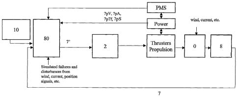
Fig. 1 illustrates prior art with a vessel 0 having sensors 8 sending sensor
signals 7
to a control system 2 which also receives command control signals from a
command
console 10, said control system providing command signals to actuators like
propellers 16, thrusters 17, and rudders 18.
Fig. 2 illustrates a simplified illustration of a system according to one
embodiment of
the invention, in which a signal modification computer 80 is inserted before
the
control system 2. The command input console 10 is also illustrated. The signal
lines
may be multiple serial lines.
Fig. 3 illustrates a simplified illustration of a system according to an
alternative
embodiment the invention, using a computer communication network for sending
sensor signals from the sensors to the signal modifier computer 80, and for
sending
the modified sensor signals to the control system 2, said control system
providing
control signals to actuators of the ship.
Description of preferred embodiments according to the inventions DP System
Interfaces
A dynamic positioning system according to the inventionmay be designed with a
number of different interface configurations. According to established
practice, a DP
System may be designed so that the DP Computer System is connected to a
measurement network and an actuator network, where the measurement network
and the actuator network are Ethernet networks, often designed as redundant
networks. The measurement network and / or the actuator network may
alternatively
be replaced by a Fieldbus or CAN-bus communication that may be redundant, or
by
wireless communication systems. Some sensors may be connected directly to the
DP Computer system with serial lines like RS232, RS422 or RS485, or by analog
and digital signal lines.
The hardware interface to the DP system, with input/output boards including
serial
interfaces, digital-to-analog converters, analog-to-digital converters,
digital interfaces,
and signal conditioning may be integrated within the DP computer cabinet, or
distributed on the vessel. Such distributed hardware interfaces may be located
in
dedicated interface electronic units or computers connected to a measurement
8
CA 02582084 2007-03-26
WO 2006/054898 PCT/N02005/000138
network. Such hardware interfaces may also be integrated into the marine
automation system computers or programmable logic computers (PLCs) on the
vessel.
A first preferred embodiment of the invention using serial lines
Consider a DP System in which
1. the DP Computer System is connected to the position reference systems with
serial lines like RS422, and where the remaining sensors of the measurement
system is connected to the DP Computer System with Serial lines like RS422,
or by analog signal lines.
2. the DP Computer System is connected to the thruster system through a
computer network that will typically be a redundant or non-redundant
Ethernet network running the UDP protocol, or by hardwired analog or digital
signals;
In a first embodiment of the present invention an external Signal modifying
computer
is used for testing purposes. This Signal modifying computer is arranged for
running
a specially developed signal modifying algorithm. In testing, one or more of
the serial
lines from position reference systems and / or the other sensors of the
measurement
system are disconnected from the DP Computer System, and are instead connected
to the Signal modifying computer. Each of the said serial lines is replaced by
a serial
line from the Signal modifying computer to the DP Computer System, so that the
sensor signal input to the DP Computer System is a signal that is generated,
i.e.
modified in the Signal modifying computer.
The signal modifying computer is not a signal simulator. The signal modifying
computer receives one or more sensor signals that in normal operation would be
input to the DP Computer System. The Signal modifying computer calculates for
testing purposes new values for said sensor signals based on the signals of
one or
more of the sensor signal that are input to the Signal modifying computer. The
said
new values for the sensor signals are transmitted with minimum internal delay
to the
DP Computer System over the serial lines from the Signal modifying computer to
the
DP Computer System.
The DP System may then be tested as follows:
9
CA 02582084 2007-03-26
WO 2006/054898 PCT/N02005/000138
1. The DP Computer System, the Power System, the Measurement System, the
Thruster System and the Operator Station of the DP System are run in their
normal operative mode.
2. The Signal modifying computer continuously receives one or more sensor
signals
from the Measurement System, generates one or more modified sensor signals
corresponding to said one or more of the sensor signals, where said modified
sensor signals are computed in the Signal modifying computer with an algorithm
that depend on the true value of said sensor signals, the Signal modifying
computer outputs said one or more modified sensor signals to the DP Computer
System.
A second preferred embodiment of the invention using a computer network
The invention may be represented by a test system for a marine vessel control
system (2) arranged for receiving real measurement signals (7) from sensors
(8) and
for output of control signals (13) to actuators (16, 17, 18).
A signal modifying computer (80) is arranged for being connected for receiving
one
or more of said real measurement signals (7).
The signal modifying computer (80) is arranged for modifying the real
measurement signals (7), preferably in a relatively short time, into modified
measurement signals (70). The modification of the real measurement signals
is not random, but takes place based on real values of said real measurement
signals. As an example, position signals from one of two or more GPS
sensors, said position signals comprising longitude and latitude, may be
modified by a constant or varying vector, said vector having a length and
direction, e.g. A length of 75 m and a direction of 30 degrees to the NNE,
representing an offset error in a GPS reading, giving an error of 75 m cos 30
to the north, and 75 m sin 30 to the east.
The signal modifying computer (80) is arranged for sending the modified
measurement signals (70) to the above-mentioned control system (2), of
which one or more of said modified measurement signal (70) input replace
some or all of said real measurement signal (8) input.
- said control system (2) arranged for acting upon said one or more modified
measurement signals (70) and remaining unaffected real measurement
signals (7);
CA 02582084 2007-03-26
WO 2006/054898 PCT/N02005/000138
The purpose of the invention is for enabling testing of said control system
(2)
function on such errors represented by said modified measurement signal (70)
imagined to occur in one or more sensors (8). As an introductory example, the
test may reveal if the system is capable of discriminating between e.g.
suddenly changing or unstable readings of one sensor, e.g a first GPS sensor,
and less varying or stable readings of a similar sensor, e.g another GPS
sensor. The test may also reveal if the system is capable of discriminating
e.g.
a high-priority position signal like a highly precise dGPS signal that by some
error occuring becomes really untrustworhy, and giving priority to an
otherwise
less precise position signal coming from e.g. a hydroacoustic transponder, but
still reliable with respect to the test situation. Such a behaviour would be
desirable in a real situation in which the transponder system continues to
function while one or both the dGPS systems should malfunction.
With reference to the drawings, in the test system according to the invention,
the
marine control system (2) is arranged for receiving input command signals (9)
from a
command input device (10) on a command signal line (11). Further, in the test
system said sensors (8) are connected to said control system using a sensor
signal
line (12).
Consider a DP System where
a) the DP Computer System is connected to the measurement system with a
computer network that will typically be (i) a redundant or non-redundant
Ethernet network running the UDP protocol, (ii) a redundant or non-redundant
Fieldbus or CAN-bus, or (iii) a wireless signal transmission protocol;
b) the DP Computer System is connected to the actuators through a computer
network
In a second embodiment of the present invention an external Signal modifying
computer is used for testing purposes. This Signal modifying computer is
arranged
for running a specially developed signal modification algorithm. In testing,
the Signal
modifying computer is connected to a computer network that connects the DP
Computer System to the Measurement System. The signal modifying computer
inputs one or more sensor signals from the Measurement System, and based on
these input sensor signals and a computer algorithm, the Signal modifying
computer
11
CA 02582084 2007-03-26
WO 2006/054898 PCT/N02005/000138
calculates modified values for said sensor signals, and the Signal modifying
computer outputs the modified sensor signals on the computer network, the
modified
signals having the DP computer as their destination.
For testing purposes, the input of the DP Computer System may be changed by
changing the list of input signals to the DP Computer System so that the DP
Computer System receives the said modified sensor signals from the Signal
modifying computer instead of the corresponding sensor signals that are
transmitted
from the Measurement System.
The DP System may then be tested as follows:
1. The Power System, the Measurement System, the Thruster System and the
Operator Station of the DP System are run in their normal operative mode.
2. The DP Computer System is set up to read one or more modified signals from
the signal modifying computer instead of the corresponding sensor signals from
the Measurement System.
3. The Signal modifying computer continuously receives one or more sensor
signals
from the Measurement System via the computer network, generates one or more
modified sensor signals corresponding to said one or more of the sensor
signals,
where said modified sensor signals are computed in the Signal modifying
computer with an algorithm that depend on the true value of said sensor
signals,
the Signal modifying computer outputs said one or more modified sensor signals
to the DP Computer System via the computer network.
With reference to the drawings, the test system according to the invention is
arranged for outputting control signals (13) to said actuators (16, 17, 18),
like
propellers (16), thrusters (17) , and rudders (18).
Further, the signal modifying computer (80) is arranged for modifying said
real
measurement signals (7) in a relatively short time into modified measurement
signals
(70), so as for said control system (2) experiencing no significant delay of
said
modified measurement signals (70) as compared to the corresponding reception
time said control system (2) would have received said real measurement signals
(7).
12
CA 02582084 2007-03-26
WO 2006/054898 PCT/N02005/000138
The test system according to the invention, said control system (2) may
comprise a
power management system including power sensors (8p?) for sensing power
signals
like generator output voltage (7pV), generator output current (7pA), generator
power
(7pP), fractional total generator, power (7pTf), generator status (7pS), and
the like.
Applications of the invention
Position reference system test arrangement
In a DP System the position of the vessel is determined on the basis of
measurement in one or more position reference systems. A position reference
system outputs (i) the position of a reference point that is fixed in the
vessel or (ii) the
heading of the vessel. A position reference system may be one of the
following:
a) A DGPS Position Reference System in which a differential GPS systems (DGPS)
that measures the position of the GPS antennae in combination with a
gyrocompass that measures the vessel course, and a vertical reference unit
that
establishes the direction of the vertical line. Other satellite navigation
systems,
like Galileo, or land-based navigation systems may be used. From these
measurements the DP Computer System can calculate the position of the vessel
reference point can be calculated by adjusting the positin of the GPS antennae
for the distance between the GPS antennae and the vessel reference point for
the measured heading and the measured direction of the vertical.
b) A hydroacoustic position reference system where a hydroacoustic measurement
system gives the position of the hydroacoustic transponder in combination with
a
gyrocompass that measures the vessel course, and a vertical reference unit
that
establishes the direction of the vertical line. From these measurements the DP
Computer System can calculate the position of the vessel reference point by
adjusting the position of the hydroacoustic transponder for the distance
between
the hydroacoustic transponder and the vessel reference point for the measured
course and the measured direction of the vertical.
c) Tautwire, Fanbeam, DARPS, ARTEMIS, Gyro compass etc.
A correctly operating position reference system is critical for the safe and
effective
performance of the DP System. Because of this it is common practice in safety-
critical operations involving DP Systems to use at least three position
reference
systems. One typical configuration is to use to DGPS position reference
systems,
13
CA 02582084 2007-03-26
WO 2006/054898 PCT/N02005/000138
and one hydroacoustic position reference system. The motivation for this is
that it is
hoped that a failure in one of the position reference systems can be
compensated for
or eliminated by using information from the two remaining position reference
systems. In several recorded incidents it has been experienced that even with
three
position reference systems it may occur that the DP System cannot establish
the
correct position when one of the reference systems has a failure. On
background of
this it important to test how and to what extent the DP System handles
malfunction
of, or failure in, one or more position reference systems.
The Signal modifying computer of the present invention is a new and useful
tool in
the testing of DP System performance if failures occur in the position
reference
systems. Such tests may be conducted as follows using the first preferred
embodiment of the invention. In the description it is assumed that the DP
system has
two DGPS systems and one hydroacoustic position reference system with
transponders on the sea-floor, and that each of the three position reference
systems
are connected to the DP Computer System with an RS232 serial line.
1. The DP Computer System, the Power System, the Measurement System, the
Actuator System and the Operator Station of the DP System are run in their
normal operative mode.
2. The RS232 serial lines of preferably each of the three position reference
systems
are disconnected from the DP Computer System, and are instead connected to
the Signal modifying computer. Said RS232 serial lines connected to the DP
Computer System are replaced by RS232 serial lines from the Signal modifying
computer to the DP Computer System.
3. The position reference signals from the three position reference sensors
are input
to the Signal modifying computer. Each of the position reference signals will
include the position of a point on the vessel, the course angle, and the
direction
of the vertical line.
4. The Signal modifying computer calculates modified position reference
signals that
would result for a given failure situation and transmits the modified position
reference signals to the DP Computer System.
5. The performance of the DP System represented by the output and other status
signals for the failure situation in the test is recorded by logging sensor
signals
14
CA 02582084 2007-03-26
WO 2006/054898 PCT/N02005/000138
input to the DP Computer System, and actuator signals output from the DP
Computer System, and possibly status signals.
To further explain how position reference tests are performed, the following
three
examples are presented in the following:
Position Reference Test 1- Reduced GPS signal quality
Position reference test 1 is a test where the Signal modifying computer is
used to
test the performance of a DP System with respect to a failure in the form of
reduced
quality of the signal from one of the GPS satellites. This is an external
error that may
incur the same erroneous position if both GPS receivers receive signals from
the
same set of satellites.Such failure situations are known to occur, and in
recorded
incidents such failure have cause DP systems to have a drive-off, which is a
potentially safety threatening incident where the DP System uses the thrusters
so
that the vessel is driven away from its assigned position in an uncontrolled
action.
The DP System under consideration is assumed to have two DGPS position
reference system and one hydroacoustic position reference system.
As explained above, the position reference systems are connected to the Signal
modifying computer instead of the DP Computer System, and the Signal modifying
computer sends modified position reference signals to the DP Computer System.
Then based on the measured antennae position from the two DGPS position
reference systems in combination with the known GPS satellite configuration at
the
time of the test, one satellite is selected for test purposes as having a
failure
condition leading to reduced quality GPS signal. Then, it is calculated what
the
change in the measured GPS antennae would be for the two DGPS position
reference systems with the reduced quality GPS signal for the said satellite.
The
Signal modifying computer then adjusts the position reference signals to
account for
the said change in antennae position of the DGPS position reference systems,
and
sends the modified position reference signals to the DP Computer System. In
this
way it is tested how the DP System handles inaccurate GPS satellite signals.
CA 02582084 2007-03-26
WO 2006/054898 PCT/N02005/000138
Position Reference Test 2- predetermined position change rate signal
discrimination
An established method which is based on textbook practices in control theory
is to
monitor the rate of variation in a sensor signal, and then to discard the
sensor signal
as invalid if the variations in the sensor signal are larger that what can be
physically
realized. The method is used in DP System to eliminate failures in position
reference
systems. In a recorded incident two DGPS position reference systems in a DP
System showed an instantaneous change in the measured position of 75 meters
due
to an error in the GPS satellite signal. Obviously, a vessel cannot
instantaneously
change its position by 75 meters, and because of this the signals from the two
DGPS
position reference were appropriately discarded as invalid by the DGPS System.
It turns out, however, that this method is not without problems. In another
recorded
incidence from offshore Angola, a sudden impact from a series of large waves
moved a vessel very quickly 25 meters away from its initial position. The DGPS
position reference systems recoded this quick change in motion correctly, but
the DP
System discarded the perfectly sound DGPS position reference signals because
the
rate of change in position was larger than the threshold value that the DP
System
was set to accept. As a result of this the vessel was left with all position
reference
systems deactivated by the DP System.
To test how the DP System handles such situations, it is proposed to use the
Signal
modifying computer iof the present invention. The position reference signals
are
input to the Signal modifying computer instead of being input to the DP
Computer
Systems as explained above. The position reference signals are used to
calculate
the position of the vessel reference point. The Signal modifying computer then
adds
a position increment to the vessel reference point corresponding to some pre-
specified quick motion that may correspond to the motion imposed from a sudden
impact of a series of large waves. the Signal modifying computer continuously
modifies the position reference signals so that these signals correspond to
the
modified motion of the vessel reference point. These modified position
reference
signals are continuously sent to the DP Control System, and it can be observed
if the
16
CA 02582084 2007-03-26
WO 2006/054898 PCT/N02005/000138
DP System can handle a given wave excitation without discarding the position
reference systems.
Position reference test 3 - hydroacoustic errors
Hydroacoustic position reference systems are use in combination with DGPS
position reference systems in DP systems. The performance of the hydroacoustic
position reference system is important especially if there are problems with
the
DGPS position reference systems.
Recorded failure situations for hydroacoustic position reference systems in DP
operations can be efficiently used for testing the control system using the
Signal
modifying computer. To do this, hydroacoustic position reference signals are
input to
the Signalmodifying computer. Then these signals are modified in a computation
in
the Signal modifying computer where the following tests are performed
a) The effect of noise with changing variance on the hydroacoustic position
reference signals is studied by adding a noise signal to the position signal
from
the hydroacoustic position reference and sending the modified signal to the DP
Computer System. This test can be extended to studying the combined effect of
noise on both hydroacoustic and DGPS position reference systems by also
adding noise signals to the DGPS position reference signals.
b) The effect on the DP System of acoustic communication errors due to
reflections
of hydroacoustic signals, poor communication between transponders on the sea-
floor, transponder failure, or transponder outage can be tested by modifying
the
hydroacoustic position reference signals using mathematical models of
hydroacoustic signal transmission and the resulting change in the position
signals.
c) The effect of a reduced sample rate of the acoustic data is tested by
modifying
the signals from the hydroacoustic position reference so that the sample rate
is
reduced from e.g. 1 Hz to e.g. 0.5 Hz.
Position reference test 4 - vertical reference errors
A vertical reference unit is used in a DP System as input to the position
reference
signals to compute the position of the vessel reference point. Failure in the
vertical
17
CA 02582084 2007-03-26
WO 2006/054898 PCT/N02005/000138
reference unit will give wrong values in the calculation of the position of
the vessel
reference point, and if the error in the vertical reference unit is more than
90
degrees, then the calculation may even break down due to possible division by
zero
in the algorithm depending on the implementation of the computations.
The effect of a failure in the position reference system is done by modifying
the
vertical reference system signals in the Signal modifying computer, and
sending the
modified signals to the DP Computer System, to test the control system's
tolerance
to such errors in vertical reference unit measurements
Wind sensor test
A DP System will normally have one or more wind sensors that measure the speed
of the wind acting on the vessel. Then according to techniques known from
textbooks
in marine engineering it is possible to calculate the forces and torques on
the vessel
due to the wind. It is then possible to use these calculations in the
algorithm of the
DP Computer to achieve improved accuracy in the DP system when the wind is
strong. It is foreseen that a wind sensor may become defect, or it may show an
incorrect value due to a failure, or because a helicopter is hovering close to
the wind
sensor.
To test how the DP System handles a failure in one of the wind sensors the
Signal
modifying computer can be used as follows: The wind sensor signal line, which
may
be an analog signal line, or a digital RS232 serial line, is disconnected from
the DP
Computer System, and the signal is instead connected to the Signal modifying
computer. The wind sensor signal line is replaced by another signal line of
the same
type that is connected to the DP Computer System, so that this signal line
transmits
a modified wind sensor signal from the Signal modifying computer to the DP
Computer System. Then the Signal modifying computer modifies the wind sensor
signal according to one of the following alternatives:
* Adding a signal with high noise variance for a defined time interval.
* Adding a drift signal so that the modified signal diverges from the sensor
signal for
a defined time interval.
* Adding a constant signal bias for a defined time interval
18
CA 02582084 2007-03-26
WO 2006/054898 PCT/N02005/000138
* Applying a signal freeze so that the modified signal is a constant value for
a defined
time interval.
The modified wind sensor signal is sent to the DP Computer System instead of
the
wind sensor signal.
Blackout prevention test of the power management system
Thrusters and propellers driven by diesel-electric systems are widely used in
ships
and floating oil installations. In these systems diesel engines are used to
drive
electrical generators that supply electrical power to an electrical power
system on the
vessel. The thrusters and propellers are driven by electrical motors that are
powered
from the electrical power system. In addition the electrical power system is
used to
drive other functions of the vessel like cranes, heave compesation, drilling,
refrigeration, and air-conditioning. A well-known problem in this type of
systems is
that if the electrical power that is used by the other functions of the vessel
is high,
then the power that is available to the thrusters and the propellers may be
insufficient
compared to what is required to achieve the thrust that is commanded by the DP
System. The same is the case for manually controlled vessels where the
operator
may require thrust corresponding to an electrical power consumption that
exceeds
the power that is available. In cases of which the available electrical power
is
insufficient, a power management system, which is a control system integrated
in the
power system, reduce the power that is distributed to the different systems
that
consume electrical power, and it may even shut down such consumers.
If the lack of available power for propulsion is not appropriately handled by
the power
management system, then there is a risk that the vessel may experience a
partial
power outage where one or more of the switchboards and power buses are shut
down, an it may even occur that the vessel will have a blackout where there is
a
complete loss of electrical power on the vessel, which is a situation that may
lead to
accidents and loss of vessel.
On the background of the above it is understood that it is important that the
function
of the power management system is extensively tested in combination with all
the
installed units of the vessel, and in particular in combination with the DP
System.
19
CA 02582084 2007-03-26
WO 2006/054898 PCT/N02005/000138
a) Consider a vessel with a DP system, of which signals indicating the power
delivered by the electrical generators are sent to the DP Computer System
under
normal operation, and the DP System is designed to appropriately reduce the
power consumption of the thrusters if the electrical power consumed by other
functions of the vessel is high. The power reduction function of the DP System
can be tested with the DP System in its normal operation at sea, with the
exception that the power indicating signals from the generators to the DP
System
are modified by the Signal modifying computer so that the modified signals
indicate that the power from the generators to other functions of the ship is
e.g
90% of the available power. It can then be tested if the DP System is capable
of
handling such a situation satisfactorily.
b) Consider another vessel with a DP system, of which signals indicating the
power
delivered by the electrical generators are sent to the power management system
and not.to the DP Computer System under normal operation, and the power
management system, and not the DP System, is designed to appropriately
reduce the power consumption of the thrusters if the electrical power consumed
by other functions of the vessel is high. The power reduction function of the
power management system can then be tested with the DP System in its normal
operation at sea, with the exception that the power indicating signals from
the
generators to the power management system are modified by the Signal
modifying computer so that the modified signals indicate that the power from
the
generators to other functions of the ship is near the total power capacity,
e.g 90%
of the available power. It can then be tested if the power management system
handles this situation satisfactorily in combination with the DP System.
Propulsion system test
Propulsion systems are critical factors in DP vesseis. The interaction between
the
control system of a thruster, the power management system and the DP Systems
can cause problems, and it is important to test these systems in combination.
A
propulsion system in this connection comprises a propeller, the electrical
thruster
motor driving the propeller, the drive controlling the pitch of the propeller
blades, the
drive controlling the azimuth angle in the case of an azimuth thruster, and
the
thruster control system that measures that shaft speed and shaft power of the
CA 02582084 2007-03-26
WO 2006/054898 PCT/N02005/000138
propeller and controls the thruster motor so that it achieves the commanded
shaft
speed of shaft power.
In a propulsion system test it is of interest to test the system when there is
an error in
one or more of the thruster pitch signal, RPM or powersignal feedback signal,
or
thruster status signals. This is done by running the system in its normal
operation
except that one or more thruster signals is modified by the Signal modifying
computer.
21