Note: Descriptions are shown in the official language in which they were submitted.
CA 02582185 2010-08-20
ALLOY FOR ROLLER BEARING
BACKGROUND OF THE INVENTION
I. Field of the Invention
[0002] The invention relates generally to an alloy for aircraft roller
bearings, as well as
an alloy for a bearing or bearing part.
2. Discussion of Background Information
[0003] During operation, roller bearings of vehicles are typically subjected
to diverse
loads and stresses, which they are to withstand for as long as possible. These
include,
e.g., dynamic mechanical loads through sliding against one another or rolling
of bearing
parts and corrosion attack by corrosive lubricants. In the case of aircraft,
an additional
problem is that working temperatures of roller bearings can be in the range of
several
hundred degrees Celsius. For example, in the case of roller bearings of
aircraft turbines
temperatures of around 250 C can be measured even in the coasting down phase
when,
although a load is slight, there is no longer any cooling.
[0004] Particularly high demands are therefore made on roller bearings for
aircraft, e.g.,
with respect to load-bearing capacity and operational life in order to be
serviceable. Great
strength and toughness, low wear and low rolling contact fatigue in use are
required as
well as a high corrosion resistance even at increased temperatures. In
addition, a surface
of the roller bearing should have a satisfactory reactivity with respect to
the additive
tricresyl phosphate, which is present in the predominantly used aviation
turbine oil, e.g.,
Mobil Jet Oil II, so that a protective reaction layer can be formed to
minimize wear. The
reactivity of the bearing surface with the lubricant additive depends
considerably on the
chemical nature of the bearing surface. Considered overall, this produces a
complex
1
CA 02582185 2010-08-20
profile of requirements for roller bearings for aircraft. This profile is to
be met by the use
of a suitable alloy.
[0005] According
to DIN 17230, the most common roller bearing materials are
subdivided into five groups, namely:
(1) through-hardenable roller bearing steels (e.g., 1000r6 or SAE 52100),
(2) case-hardening steels (e.g., 17MnCr5 or SAE 8620),
(3) quenched and tempered steels (e.g., 43CrMo4 or SAE 4340),
(4) corrosion-resistant steels (e.g., AISI 440C, X30CrMoN15 or X45Cr13), and
(5) heat-resistant steels and hard alloys (e.g., M50 or AISI Ti).
[0006] Out of the available material groups, heat-resistant steels have become
accepted
for the bearings of aircraft, whereby the alloy M50, a low-alloy high-speed
steel, and
variants of this alloy are chiefly used. The leading role held for decades by
the alloy M50
as roller bearing material for aircraft is due to its mechanical properties
and good fatigue
properties. However, the corrosion resistance is completely unsatisfactory,
but this has
been tolerated until now due to a lack of alternative alloys.
[0007] Since
there is a consistent desire for more efficient and more reliable roller
bearings, attempts are being made to find improved alloys comparable to alloy
M50. For
example, U.S. Pat. No. 4,150,978 discloses individual alloys in the
composition
range (in % by weight) 0.8 to 1.6% carbon, max. 0.5% silicon, max. 0.5%
manganese, max. 0.1% sulfur, max. 0.015% phosphorus, 12 to 20% chromium,
2 to 5% molybdenum, up to 3% tungsten, 0.5 to 3.0% vanadium, up to 0.5%
titanium, max. 0.03% aluminum, max. 0.5% nickel, max. 0.5% cobalt, max.
0.5% copper, max. 0.05% boron, max. 0.05% nitrogen, the balance being iron
and impurities. Compared to M50, these alloys exhibit a better behavior in the
rolling contact test and should also be useable in corrosive media, but have
not
become accepted in practice.
[0008] Another approach today lies in using surface hardening of corrosion-
resistant
alloys with max. 0.1% by weight carbon and chromium contents of at least 13%
by
weight. However, in order to obtain adequate surface hardnesses and thus an
adequate
2
=
CA 02582185 2007-03-19
wear resistance, these materials have to be subjected to case hardening
methods, such as,
e.g., carburization and nitridation. However, the corrosion properties can be
considerably
affected by the carburization or nitridation process.
[0009] Although known alloys for aircraft roller bearings can in each case
conform to
several properties with regard to the profile of requirements described at the
outset, they
fall down considerably on at least one property, e.g., corrosion resistance.
Such a drop-off
in one property is usually enough to reduce the operational life
substantially, thus
restricting the field of application for a roller bearing. It is ultimately
irrelevant for the
value and the useful life of a roller bearing whether it needs to be replaced
due to the
occurrence of fatigue or corrosion. In other words, the best mechanical
properties cannot
be utilized if corrosion leads to premature failure of the bearing.
Conversely, the highest
corrosion resistance is useless if fatigue fractures and/or premature wear
occur after a
short time in use.
SUMMARY OF THE INVENTION
[0010] The present invention provides an alloy from which it is possible to
produce
roller bearings that also have high corrosion resistance in addition to good
mechanical
properties, low wear and low rolling contact fatigue.
[0011] The present invention also provides bearings or bearing parts, in
particular roller
bearings or roller bearing parts, that also have high corrosion resistance in
addition to
good mechanical properties, low wear and low rolling contact fatigue.
[0012] In one
exemplary embodiment, the present invention provides an alloy for
aircraft roller bearings containing:
0.45 to 1.0 wt. % carbon,
max 2.0 wt. % manganese,
max 1.0 wt. % silicon,
8.5 to 11.5 wt. % chromium,
1.0 to 4.5 wt. % molybdenum,
1.0 to 2.5 wt. % vanadium,
max 2.0 wt. % tungsten,
max 0.5 wt. % niobium,
3
CA 02582185 2007-03-19
max 0.5 wt. % tantalum,
max 3.0 wt. % nickel,
max 0.5 wt. % cobalt,
max 0.1 wt. % aluminum,
max 0.01 wt. % nitrogen, and
the balance being iron and impurities due to production.
[0013] Carbon may be present in the alloy in an amount of 0.55 to 0.85 wt. %
[0014] Carbon may be present in the alloy in an amount of up to 0.75 wt. %.
[0015] Chromium may be present in the alloy in an amount of 9.5 to 10.5 wt. %.
[0016] Molybdenum may be present in the alloy in an amount of 2.5 to 3.5 wt.
%.
[0017] Molybdenum may be present in the alloy in an amount of 2.65 to 3.25 wt.
%.
[0018] Vanadium may be present in the alloy an amount of 1.65 to 2.25 wt. %.
[0019] Vanadium may be present in the alloy in an amount of 1.8 to 2.5 wt. %.
[0020] Tungsten may be present in the alloy an amount of 0.5 wt. % max.
[0021] Manganese may be present in the alloy in an amount of 0.3 wt. % max.
[0022] Silicon may be present in the alloy in an amount of 0.05 to 0.2 wt. %.
= [0023] Nickel may be present in the alloy in an amount of 0.5 wt. % max.
[0024] Carbide may be present in the alloy in an amount of 0.5 to 7% by
volume.
4
CA 02582185 2007-03-19
[0025] Metal carbides of the type M7C3 may be present in the alloy in an
amount less
than 3% by volume.
[0026] The present invention also provides a bearing or bearing part made from
the
alloy of the present invention. In one embodiment, the bearing or bearing part
further
includes a roller bearing or roller bearing part.
[0027] The present invention also provides a method of using an alloy
according to the
present invention, including using the alloy as a part or component in an
aircraft.
[0028] The advantages of the alloy according to the present invention lie in
particular in
its profile of properties, based on which the alloy is excellently suitable
for aircraft roller
bearings. This profile of properties includes in particular high strength, low
wear and
good rolling contact fatigue in use as a roller bearing material and an
extraordinarily high
corrosion resistance. In order for this profile of properties to be attained,
the contents of
individual alloying elements are coordinated in a targeted manner, whereby the
contents
according to the invention are the expression of the effects of individual
alloying
elements as well as the interactions among them. These effects are described
below.
[0029] With an alloy according to the invention, in addition to iron and
impurities due
to manufacture, elements are also present in the following amounts (all in
percentage by
weight unless otherwise noted):
[0030] Carbon (C) is provided in an amount of 0.45 to 1.0% in order to give an
alloy
according to the invention a high degree of hardness. With contents above 1.0%
there is a
danger that particularly the chromium-rich metal carbides of the type M7C3
will form,
whereby this metal, which is responsible for a corrosion resistance, is
extracted from the
matrix, with a consequent decrease in corrosion resistance. Moreover these
M7C3
carbides are coarse, which has a negative effect on wearing behavior with
bearings.
Carbon contents below 0.45% lead to low hardness and there is the possibility
that
undesirable ferrite will be formed during production. An optimal content of
carbon lies
in the range of 0.55 to 0.75%. In this content range, a favorable carbide
morphology,
CA 02582185 2007-03-19
namely chiefly development of MC carbides or MC mixed carbides, can be
achieved.
MC carbides contribute to a high degree of hardness, but do not impair the
corrosion
resistance, since only a small amount of chromium necessary for the formation
of the
passive layer is extracted from the matrix.
[0031] Manganese (Mn) can be present in the alloy in an amount of up to a
maximum
of 2.0% manganese (Mn). In order to keep a formation of residual austenite
low, a
manganese content is preferably restricted to a maximum of 0.3%.
[0032] Silicon (Si) is necessary for deoxidization and can be provided in an
amount up
to a maximum of 1.0%. Since silicon can have a considerable embrittling effect
and
promote a formation of 8 ferrite, it is advantageous to keep silicon contents
in the range
of 0.05 to 0.2%.
[0033] Like silicon, aluminum (Al) promotes a formation of 8 ferrite.
Therefore, the
amount of aluminum content should be no more than 0.1%.
[0034] Chromium (Cr) is provided in an amount of 8.5 to 11.5%. Chromium
amounts
above 11.5% can lead to the increased formation of coarse M7C3 carbides which,
as
mentioned, have a negative effect on corrosion resistance. The desired
corrosion
resistance cannot be achieved with chromium amounts below 8.5%. A chromium
amount
coordinated with the carbon content preferably lies in the range of 9.5 to
10.5%. In this
range proportions of M7C3 carbides are low, and an extremely high corrosion
resistance is
achieved with good mechanical properties.
[0035] Molybdenum (Mo) is present in an amount of 1.0 to 4.5% and in this
range, can
contribute positively to a high corrosion resistance. Amounts higher than 4.5%
with
present carbon amounts, surprisingly do not lead to any further increase in
the corrosion
resistance. Instead, with higher amounts of molybdenum and given carbon, the
corrosion
resistance tends to decrease. This can be explained by an increased formation
of M7C3
and/or M6C carbides, which can lead to a molybdenum depletion of the matrix
and thus
to increased susceptibility to corrosion.
[0036] Vanadium (V) is present in an amount of 1.0 to 2.5% and in this range,
can
effectively promote a formation of desirable MC carbides. With amounts higher
than
6
CA 02582185 2007-03-19
2.5%, the precipitation of coarse carbides from the melt can occur during
production.
These coarse carbides are undesirable, since the rolling or sliding properties
of bearings
can be negatively affected.
[0037] With vanadium (V) amounts lower than 1.0%, the effectiveness decreases
with
respect to the formation of MC carbides.
[0038] Tungsten (W) can be provided in amounts up to 2.0%. Amounts higher than
2.0% can be detrimental, since, as with molybdenum contents of above 4.5%, in
particular M6C carbides can be formed and in addition the tendency to form
M7C3 in
combination with the present chromium contents increases. Therefore, the
tungsten
amount is preferably limited to 0.5%.
[0039] Niobium (Nb) and tantalum (Ta) can be respectively present in an
alloy
according to the present invention with a maximum of 0.5% and in these low
amounts,
can promote a formation of MC carbides. Amounts higher than 0.5% can lead to
the
direct precipitation of coarse carbides from the melt. These coarse carbides
are
undesirable, since the rolling or sliding properties of bearings can be
negatively affected.
[0040] Cobalt (Co) can be present in an amount up to a maximum of 0.5%. At
increased tempering temperatures, cobalt (Co) can have a negative effect on
corrosion
resistance, since it increases the affinity to form M7C3 carbides.
Furthermore, with
increasing cobalt (Co) content, the toughness of samples tempered above the
secondary
hardness maximum deteriorates drastically. It is therefore advantageous to
limit the
cobalt (Co) amount to less than 0.2%.
[0041] Like cobalt (Co), nickel (Ni) can reduce the corrosion resistance
due to
increased affinity to M7C3 carbide formation, but increasing Ni content can
result in
improved ductility properties. Depending on the profile of requirements, the
aim should
be a nickel (Ni) amount of 0 to 3%.
[0042] Nitrogen (N) can promote a residual austenite formation and should
therefore be
present in an amount of no more than 0.01%.
[0043] The present invention further provides a bearing or bearing part
including the
alloy as noted above. Since the bearing or bearing part fulfills a complex
profile of
7
CA 02582185 2007-03-19
requirements with respect to strength, favorable wearing behavior and low
rolling contact
fatigue and in addition has an extraordinarily high corrosion resistance, a
long operational
life is given. The advantages of a bearing or bearing part according to the
invention are to
be seen in particular herein and in its high load-bearing capacity even with
contact with
corrosive media or the like.
[0044] Further advantages and effects of the invention are apparent from the
context of
the specification and the exemplary embodiments.
[0045] The invention is presented more extensively below based on test results
and in
comparison with the prior art.
BRIEF DESCRIPTION OF THE DRAWINGS
[0046] The present invention is further described in the detailed
description which
follows, in reference to the noted plurality of drawings by way of non-
limiting examples
of exemplary embodiments of the present invention, in which like reference
numerals
represent similar parts throughout the several views of the drawings, and
wherein:
Fig. 1: Depicts a test arrangement to carry out ball-on-disk (BOD) tests;
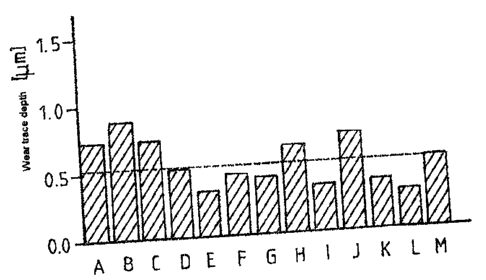
Fig. 2: Shows a diagram of the wear trace depth in BOD tests for alloys A
through M;
Fig. 3: Shows a graph of the operational life achieved for samples of
alloys D and
M with rollover tests;
Fig. 4: Shows pitting potential, rest potential and repassivation
potential for alloys
A through E;
Figs. 5(a) and 5(b): Shows micrographs of alloys D and G, respectively;
Fig. 6: Shows pitting potential, rest potential and repassivation
potential for alloys
H, I and J compared to alloy D;
Fig. 7: Shows pitting potential, rest potential and repassivation potential
for alloys
K and L compared to alloy D;
Fig. 8: Shows current density potential curves of alloy D for different
tempering
temperatures;
8
CA 02582185 2007-03-19
Fig. 9: Shows a
diagram of the hardness pattern and the pattern of the pitting
potential of alloy D for different tempering temperatures;
Figs. 10(a) ¨ (b): Show
transmission electron microscopy (TEM) and chromium
distribution images, respectively, of alloy D after a triple tempering for
two hours at 4000; and
Figs. 10(c) ¨ (d): Show
transmission electron microscopy (TEM) and chromium
distribution images, respectively, of alloy D after a triple tempering for
two hours at 560 C.
DETAILFD DESCRIPTION OF THE INVENTION
[0047] The
particulars shown herein are by way of example and for purposes of
illustrative discussion of the embodiments of the present invention only and
are presented
in the cause of providing what is believed to be the most useful and readily
understood
description of the principles and conceptual aspects of the present invention.
In this
regard, no attempt is made to show structural details of the present invention
in more
detail than is necessary for the fundamental understanding of the present
invention, the
description taken with the drawings making apparent to those skilled in the
art how the
several forms of the present invention may be embodied in practice.
[0048] Table 1 shows chemical compositions of tested alloys. The alloys were
smelted
or remelted in vacuum. The workpieces thus produced were subsequently
subjected to a
heat treatment comprising austenitization, quenching and triple tempering for
two hours.
A residual austenite content was lower than 6 percent by volume in every case.
Table 1: Chemical compositions of tested alloys A through M
Chemical composition fin % by weight]
Alloy C Cr V Mo Ni Co Si Mn Fe
A 0.66 3.92 1.55 2.96 0.04 0.15 0.23 Bal.
9
= CA 02582185 2007-03-19
B 0.69 5.92 1.63 3.00 0.04
0.19 0.26 Bal.
C 0.67 7.79 1.76 2.87 0.03 0.16 0.25 Bal.
D 0.60 10.10 1.99 2.90 0.04 0.19 0.21 Bal.
E 0.62 12.01 2.10 2.76 0.04
0.20 0.24 Bal.
= F 0.57 9.84 2.00 1.44 0.02
0.15 0.22 Bal.
G 0.69 9.61 1.90 4.24 0.05
0.15 0.25 Bal.
H 0.62 9.84 1.59 2.80 0.04 4.93 0.18 0.24 Bal.
I 0.61 9.97 1.61 2.80 0.05 10.00 0.18 0.27 Bal.
J 0.71 10.03 1.56 2.87 0.05 14.91 0.19 0.26 Bal.
K 0.64 9.94 1.73 2.87 1.49 0.16 0.21 Bal.
L 0.67 9.85 1.63 2.78 2.98 4.92 0.18 0.26 Bal.
M 0.79 4.10 1.04 4.20 0.05 0.20 0.26 Bal.
I. Characteristic strength values
[0049] The characteristic strength values and characteristic expansion values
of alloys
A through L and reference alloy M, which corresponds to the roller bearing
material
M50, were determined in the heat-treated state. In every case the heat
treatment
comprised an austenitization at a temperature between 1100 C and 1200 C,
followed by
a quenching and a triple tempering of the alloy at temperatures between 510 C
and
585 C; the hardnesses were 59 1 HRC. It was shown that with these hardnesses
tensile
strength values R0.2 or Rnõ of respectively more than 1700 MPa or 2000 MPa
were
achieved for all the alloys. Alloy D, for example, had an Rp0.2 value of 2000
MPa and an
R. value of 2334 MPa and thus lies in the range of the values of reference
alloy M.
[0050] With respect to the characteristic expansion values, in particular the
elongation
at break, alloys A through D, H, I, K and L are clearly superior to the alloy
M. For
example, alloys A through D have an elongation at break higher by 50% (e.g.,
alloy D of
= CA 02582185 2007-03-19
4.44% compared to 2.55% of alloy M). Within the measurement uncertainty alloys
E and
F have an elongation at break approximately in the range of alloy M. Alloy J
has an
elongation at break of only 0.07%.
[0051] The strengths and expansion values determined show that the alloys
tested, with
the exception of alloy J, meet the minimum requirements for strength and
expansion for
materials for roller bearings.
II. Ball-on-disk tests
[0052] Alloys A through M were tested for their wearing behavior by means of
the ball-
on-disk test method, as shown in Fig. 1, and the wear trace depth was
measured. In order
to achieve comparable lubrication conditions in the BOD test as in the
aircraft engine
bearing, an identical X value of 0.8 (characteristic number for the contact
conditions in
the lubrication gap) was set. The test parameters were:
Radius of the trace: 5 mm
Sliding velocity: 10 cm/s
Force applied: 15 N
Length of the wear trace: 1000 m
Ball diameter: 6 mm
Ball material: alloy M
Temperature: 150 C
Ambient medium: oil (Mobil Jet Oil II)
[0053] The results of these tests are shown in Fig. 2. As can be seen, a wear
trace depth
for alloys D through G and I, K and L, was smaller than for alloy M. This
shows that
these alloys are excellently suitable as bearing materials with respect to
wearing
behavior.
III. Rollover properties (roll contact fatigue test)
11
CA 02582185 2007-03-19
[0054] Rollover tests were carried out deliberately with elevated surface
pressure with a
three-ball-against-shaft tester. A maximum pressure of 6400 GPa prevailed in
the contact
area under test conditions.
[0055] The results or the Weibull distributions showed that alloys A through
L, with the
exception of alloy J, yield an operational life that is the same as or greater
than that of
alloy M in the rollover test. With respect to rollover characteristics, it is
shown in
particular for alloy D that this alloy has much better properties compared to
alloy M (see
Fig. 3): During rollover there is a failure probability of 10% for alloy D
with 5.50 x 10⁶
reversal of load. With alloy M the same failure probability is already
achieved at 1.57 x
106 reversals of load.
IV. Corrosion resistance
[0056] To sum up the test results shown under I through III, it can be stated
that alloys
D, E, F, G, I, K and L the requirements with respect to strength, expansion,
wearing
behavior and rollover characteristics lie in the range of alloy M or the
standard material
M50 and therefore meet the requirements in this respect for roller bearing
materials.
[0057] Tests were conducted to test the corrosion resistance of the alloys. In
particular,
the alloys were tested to see if they could be used in corrosive media, which
is not the
case for the rapidly corroding high-speed steel M50 or alloy M. These tests
were carried
out by recording current density potential curves in an aqueous sodium
chloride solution
with a content of 50 ppm chloride ions. From these records the pitting
potential was read
off for the individual alloys.
[0058] Fig. 4
shows that for alloys A through E, thus with increasing chromium
content, the pitting potential or the corrosion resistance of alloy A up to
alloy D
increases, then decreases again with alloy E. Since the chromium content is
too low,
alloys A, B and C do not exhibit the desired corrosion resistance, but alloy D
does. Alloy
E has a higher chromium content than alloy D, which is why a higher PREN value
is
given. The PREN value (calculated according to: PREN = % Cr + 3.3% Mo*(16-
30%N))
stands for corrosion resistance and one skilled in the art would expect a
higher corrosion
resistance with higher PREN value. In fact, however, M7C3 carbides precipitate
with
increasing chromium content, in particular above 11.5% by weight. Although
carbides of
12
CA 02582185 2007-03-19
'
this type provide hardness, according to their stoichiometry they have a high
chromium
content. The result is that the formation of carbides of this type leads to
the extraction of
chromium from the matrix, which reduces a corrosion resistance.
[0059] With
regard to the effects of different molybdenum contents, the highest
corrosion resistance with alloys according to the invention was determined
with alloy D,
in which mainly MC carbides are present. A lower molybdenum content is given
in alloy
F, which leads to a lower corrosion resistance. However, in alloy G, although
a
molybdenum content is higher, proportions of M7C3 carbides are also higher and
in
addition M6C carbides also occur, as can be seen from Figs. 5(a) and 5(b).
Despite higher
molybdenum content, alloy G is therefore less corrosion-resistant than alloy
D.
[0060] The influence of cobalt and nickel is evident from Figs. 6 (Co) and 7
(Ni). It is
true for both elements that the corrosion resistance decreases with increasing
content.
Accordingly, alloys I, J, K and L cannot provide the required corrosion
resistance. The
reason for this probably lies in the increased affinity for forming M7C3
carbides, which is
caused by cobalt and/or nickel.
[0061] To sum up the corrosion tests, it can be stated that alloys D, F, G and
H meet the
requirements for the corrosion properties.
[0062] In an
overall consideration of mechanical properties, wearing properties and
rollover properties as well as corrosion resistance, it is thus shown that
alloys D, F and G
have the set profile of properties, whereas the other alloys tested do not
reach a minimum
value at least with respect to one property.
[0063] An alloy D produced on an industrial scale was finally also tested with
respect
to changes in properties with differing tempering temperature. It was thereby
surprisingly
shown that a corrosion resistance depends on the tempering temperature. As
current
density potential curves in Fig. 8 show, a high pitting potential is given for
alloy D at
tempering temperatures up to 450 C. However, at a higher tempering temperature
of
560 C, a lower pitting potential of approx. + 20 mV is given.
[0064] Fig. 9 shows patterns of the pitting potential and the hardness with
variation of
the tempering temperature. It is evident that the pitting potential is over +
160mVsce at
13
= '= CA 02582185 2007-03-19
tempering temperatures up to 450 C, and after that drops sharply to approx. 40
to 60
mVsee. On the other hand it is also evident that a hardness of 59 HRC that is
desirable for
practice can already be achieved at temperatures below 450 C. Optimal results
both with
regard to mechanical properties and wearing behavior as well as with regard to
high
corrosion resistance can thus be obtained at tempering temperatures up to 450
C.
[00651 Figs. 10(a) and (c) finally shows TEM images, and Figs. 10(b) and 10(d)
show
Cr mapping images, for an alloy D that was tempered at 400 C or 560 C. The Cr
mapping images show that with the alloy tempered at 560 C (Fig. 10(d)) light
areas are
given in the boundary areas of the carbides, which suggests a high chromium
content in
some areas. In contrast, the surrounding matrix appears darker due to a low
chromium
content. This shows that the matrix in the surface area of the secondary
carbides is
depleted in chromium at higher tempering temperatures, which leads to a
reduction in the
corrosion resistance.
[0066] Tests on the carbide content of alloys D produced on an industrial
scale and heat
treated showed that a content of MC carbides was between 0.7 percent by volume
at an
austenitization temperature of 1140 C and 1.8 percent by volume at an
austenitization
temperature of 1080 C. A content of M7C3 carbides was 0.2% by volume
(austenitization
temperature of 1140 C) or no M7C3 carbides could be determined
(austenitization
temperature of 1080 C). In every case, therefore, more than 75% of the
available carbides
are present as MC carbides.
[0067] It is noted that the foregoing examples have been provided
merely for the
purpose of explanation and are in no way to be construed as limiting of the
present
invention. While the present invention has been described with reference to an
exemplary embodiment, it is understood that the words which have been used
herein are
words of description and illustration, rather than words of limitation.
Changes may be
made, within the purview of the appended claims, as presently stated and as
amended,
without departing from the scope and spirit of the present invention in its
aspects.
Although the present invention has been described herein with reference to
particular
means, materials and embodiments, the present invention is not intended to be
limited to
the particulars disclosed herein; rather, the present invention extends to all
functionally
14
CA 02582185 2007-03-19
equivalent structures, methods and uses, such as are within the scope of the
appended
claims.
[0068] Further, when an amount, concentration, or other value or parameter, is
given as
a list of upper preferable values and lower preferable values, this is to be
understood as
specifically disclosing all ranges formed from any pair of an upper preferred
value and a
lower preferred value, regardless whether ranges are separately disclosed.