Note: Descriptions are shown in the official language in which they were submitted.
CA 02582370 2007-03-29
WO 2007/015703 PCT/US2005/035175
COMPUTERIZED CONTROL METHOD AND SYSTEM
FOR MICROFLUIDICS AND COMPUTER PROGRAM
PRODUCT FOR USE THEREIN
CROSS-REFERENCE TO RELATED APPLICATION
This application claims the benefit of U.S. provisional application
Serial No. 60/614,781, filed September 30, 2004. This application is a
continuation-in-part application of U.S. application Serial No. 10/548,652,
filed
September 8, 2005, which was filed on March 10, 2004 as PCT application No.
PCT/US2004/007246, which, in turn, claims the benefit of U.S. provisional
application Serial No. 60/403,298, filed March 10, 2003.
STATEMENT REGARDING FEDERALLY SPONSORED
RESEARCH OR DEVELOPMENT
This invention was made with Government support under Contract
No. DAAD 19-03-1-0168 awarded by the Army. The Government has certain
rights to the invention.
BACKGROUND OF THE INVENTION
1. Field of the Invention
The present inventions relates to computerized control methods and
systems for microfluidic devices and computer program products for use
therein.
2. Background Art
Microfluidic devices are miniature devices that generally include a
plurality of interconnected microchannels, reservoirs, and the like, of very
small
size. Microchannels may commonly have width and height dimensions of 10 m
to 300 m, for example, although smaller and larger dimensions are possible as
well. Microfluidic systems often include numerous independently controlled
-1-
CA 02582370 2007-03-29
WO 2007/015703 PCT/US2005/035175
microfluidic pin actuators for controlling flow in the microchannels. As the
number
of actuators increases, user control of individual actuators becomes
problematic as
the user designates the state or control of each actuator.
What is needed is a system and method for controlling the operation
of the actuators and, consequently, flow in the channels in the microfluidic
device
and, thereby, the operation of the microfluidic device.
SUMMARY OF THE INVENTION
The present invention may provide an improved computerized control
method and system for microfluidics and computer program product for use
therein,
wherein independent controls are provided.
Process characteristics and microfluidic device characteristics are
retrieved in response to user input. Flow in a channel in the device is
controlled
based on the retrieved characteristics.
The features and advantages described in the specification are not all
inclusive and, in particular, many additional features and advantages will be
apparent to one of ordinary skill in the art in view of the drawings,
specification,
and claims. Moreover, it should be noted that the language used in the
specification
has been principally selected for readability and instructional purposes, and
may not
have been selected to delineate or circumscribe the inventive subject matter.
BRIEF DESCRIPTION OF THE DRAWINGS
FIGURE 1 is a block diagram illustrating a microfluidic device
system;
FIGURE 2 is a side schematic view of a microfluidic device including
an external, non-integral tactile actuator;
-2-
CA 02582370 2007-03-29
WO 2007/015703 PCT/US2005/035175
FIGURES 3a through 3c are cross-sectional views of the device of
Figure 2 including the actuator taken along lines 3-3 and illustrating the
action of the
device of Figure 2;
FIGURE 4 is a top view of a microfluidic device including tactile
actuators to select or control inlet flow and to pump or mix fluid;
FIGURE 5 is a cross-sectional view illustrating a microfluidic channel
having flanking voids to facilitate restriction of the channel by a tactile
actuator;
FIGURE 6 is an exploded perspective view of layers of an integral
microfluidic device including two tactile actuator sensor arrays;
FIGURE 7 is a perspective view illustrating an assembled
microfluidic device of Figure 6;
FIGURE 8 is a block diagram illustrating software executed by a
computer of the microfluidic device system of Figure 1;
FIGURE 9 is a block diagram flow chart illustrating operation of the
software of Figure 8;
Figure 10 is a UML class diagram illustrating the software objects
implemented for coding software that controls the microfluidic devices;
Figure 11 is a UML sequence diagram illustrating a message
sequence of objects described in Figure 10 ("Control","Dot" , and "Hardware
Wrapper") to control one Braille pin;
Figure 12 is a UML sequence diagram illustrating a message
sequence of objects described in Figure 10 ("Control", "Timed Dot State", and
"Hardware Wrapper") to control two Braille pins with a specified timing
sequence;
-3-
CA 02582370 2007-03-29
WO 2007/015703 PCT/US2005/035175
Figure 13 is a UML sequence diagram illustrating a message
sequence of objects described in Figure 10 ("Control", "Timed Dot State", and
"Hardware Wrapper") to control two Braille pins with a specified timing
sequence;
Figure 14 is a UML sequence diagram illustrating a message
sequence of objects described in Figure 10 ("Control", "Key State", and "Timed
Dot State") to activate/deactivate the timing of a Braille pin by key inputs
from a
user;
FIGURE 15 illustrates an example of a microfluidic device library of
the software of Figure 8;
FIGURE 16 illustrates an example of a process library of the software
of Figure 8; and
FIGURE 17 illustrates an example of an actuator map of the software
of Figure 8.
DETAILED DESCRIPTION OF THE PREFERRED EMBODIMENTS
Embodiments of the present invention are now described with
reference to the figures where like reference numbers indicate identical or
functionally similar elements.
Reference in the specification to "one embodiment" or to "an
embodiment" means that a particular feature, structure, or characteristic
described
in connection with the embodiments is included in at least one embodiment of
the
invention. The appearances of the phrase "in one embodiment" in various places
in the specification are not necessarily all referring to the same embodiment.
Some portions of the detailed description that follows are presented
in terms of algorithms and symbolic representations of operations on data bits
within
a computer memory. These algorithmic descriptions and representations are the
-4-
CA 02582370 2007-03-29
WO 2007/015703 PCT/US2005/035175
means used by those skilled in the data processing arts to most effectively
convey
the substance of their work to others skilled in the art. An algorithm is
here, and
generally, conceived to be a self-consistent sequence of steps (instructions)
leading
to a desired result. The steps are those requiring physical manipulations of
physical
quantities. Usually, though not necessarily, these quantities take the form of
electrical, magnetic or optical signals capable of being stored, transferred,
combined, compared and otherwise manipulated. It is convenient at times,
principally for reasons of common usage, to refer to these signals as bits,
values,
elements, symbols, characters, terms, numbers, or the like. Furthermore, it is
also
convenient at times, to refer to certain arrangements of steps requiring
physical
manipulations of physical quantities as modules or code devices, without loss
of
generality.
It should be borne in mind, however, that all of these and similar
terms are to be associated with the appropriate physical quantities and are
merely
convenient labels applied to these quantities. Unless specifically stated
otherwise
as apparent from the following discussion, it is appreciated that throughout
the
description, discussions utilizing terms such as "processing" or "computing"
or
"calculating" or "determining" or "displaying" or "determining" or the like,
refer
to the action and processes of a computer system, or similar electronic
computing
device, that manipulates and transforms data represented as physical
(electronic)
quantities within the computer system memories or registers or other such
information storage, transmission or display devices.
Certain aspects of the present invention include process steps and
instructions described herein in the form of an algorithm. It should be noted
that the
process steps and instructions of the present invention could be embodied in
software, firmware or hardware, and when embodied in software, could be
downloaded to reside on and be operated from different platforms used by a
variety
of operating systems.
The present invention also relates to an apparatus for performing the
operations herein. This apparatus may be specially constructed for the
required
-5-
CA 02582370 2007-03-29
WO 2007/015703 PCT/US2005/035175
purposes, or it may comprise a general-purpose computer selectively activated
or
reconfigured by a computer program stored in the computer. Such a computer
program may be stored in a computer readable storage medium, such as, but is
not
limited to, any type of disk including floppy disks, optical disks, CD-ROMs,
magnetic-optical disks, read-only memories (ROMs), random access memories
(RAMs), EPROMs, EEPROMs, magnetic or optical cards, application specific
integrated circuits (ASICs), or any type of media suitable for storing
electronic
instructions, and each coupled to a computer system bus. Furthermore, the
computers referred to in the specification may include a single processor or
may be
architectures employing multiple processor designs for increased computing
capability.
The algorithms and displays presented herein are not inherently
related to any particular computer or other apparatus. Various general-purpose
systems may also be used with programs in accordance with the teachings
herein,
or it may prove convenient to construct more specialized apparatus to perform
the
required method steps. The required structure for a variety of these systems
will
appear from the description below. In addition, the present invention is not
described with reference to any particular programming language. It will be
appreciated that a variety of programming languages may be used to implement
the
teachings of the present invention as described herein, and any references
below to
specific languages are provided for disclosure of enablement and best mode of
the
present invention.
The present invention provides a computerized system for controlling,
regulating, and detecting processes, flows, and operations of a microfluidic
device.
Software executed by the system controls actuators or other devices to control
fluidic flow with the microfluidic device, such as flow within microchannels
in the
device. The software may receive user input from a graphical user interface
and
may automate fluidic movement in the absence of user presence.
Figure 1 is a block diagram illustrating a microfluidic device system,
generally indicated at 100. A.computer 102 executes software for controlling
-6-
CA 02582370 2007-03-29
WO 2007/015703 PCT/US2005/035175
processes, flows and operations of a microfluidic device 110 though a
controller 106
that provides control signals and voltages to an actuator system or actuators
108.
The controller 106 may be connected to the computer 102 by a Universal Serial
Bus
(USB). The computer 102 may provide a menu of the processes, flows and
operations to a user via a user interface 104, and receive user selections via
the user
interface 104.
The actuator system 108 may be an electronically controlled and
addressable tactile display to operate as active component actuators on the
microfluidic device 110. The actuator system 108 may include Braille cells
with
actuators, such as pins, for engaging corresponding elements of the
microfluidic
device 110 in response to the control signals and voltages from the controller
106
to control fluid processes in the device 110. The software may control the
actuator
system 108 to, in turn, control fluidic operations, such as valving, pumping,
mixing,
and cell crushing, in the microfluidic device 110. The software may control
each
actuator individually and simultaneously with the control of the other
actuators 108.
The software may receive user input for operations of individual actuators or
for
processes to be performed by the microfluidic device 110. The software
configures
the controller 106 based on a user-requested process using characteristics of
the
microfluidic device 110 and the actuator system 108. The software may be coded
using any object oriented programming (OOP) language, such as Microsoft Visual
C + + environment, or may be coded using other programming languages.
The microfluidic device 110 is suitable for the culture of a living
organism in a fluid. The microfluidic device 110 controls the flow and
composition
of fluids provided to the living organism. The microfluidic device 110 may
provide
laminar, pseudo-multiple laminar or non-laminar flows. The microfluidic device
110 may perform physical operations on the living organism. The microfluidic
device 110 may be used, for example, for general cell culture including cell
washing
and detachment, cell seeding and culture. The microfluidic device 110 may be
used
as a microreactor, a tissue culture device, a cell culture device, a cell
sorting device,
a cell crushing device, a micro flow cytometer, a motile sperm sorter, a micro
carburetor, a micro spectrophotometer, or a microscale tissue engineering
device.
-7-
CA 02582370 2007-03-29
WO 2007/015703 PCT/US2005/035175
The microfluidic device 110 includes sensors 112 to determine states or flow
characteristics of elements of the microfluidic device 110 or the passage of
particles
in a channel. The sensors 112 may be, for example, optical, electrical, or
electromechanical sensors. The microfluidic device 110 may be, for example, a
microfluidic device described in PCT Patent Application No. PCT/US
2004/007246,
entitled "Integrated Microfluidic Control Employing Programmable Tactile
Actuators," filed March 10, 2004, which is incorporated by reference herein
its
entirety. The microfluidic devices described herein may be formed as described
in
the PCT Application. The microfluidic device 110 is next described.
In one embodiment, the microfluidic device 110 includes
microchannels having flow characteristics that are actively varied and formed
in a
compressible or distortable elastomeric material. In one embodiment, the
entire
microfluidic device 110 is constructed of a flexible elastomeric material,
such as an
organopolysiloxane elastomer ("PDMS"), as described hereinafter. However, the
device substrate may also be constructed of hard, e. g. , substantially non-
elastic
material at portions, where active control is not desired.
The microfluidic devices may contain at least one active portion that
alters the shape and/or volume of chambers or passageways ("empty space"),
particularly fluid flow capabilities of the device. Such active portions
include,
without limitation, mixing portions, pumping portions, valving portions, flow
portions, channel or reservoir selection portions, cell crushing portions, and
unclogging portions. These active portions all induce some change in the fluid
flow,
fluid characteristics, channel or reservoir characteristics, by exerting a
pressure on
the relevant portions of the device, and thus altering the shape and/or volume
of the
empty space which constitutes these features. The term "empty space" refers to
the
absence of substrate material. In use, the empty space is usually filled with
fluids
or microorganisms.
The active portions of the device are activatable by pressure to close
their respective channels or to restrict the cross-sectional area of the
channels to
accomplish the desired active control. To achieve this purpose, the channels,
-8-
CA 02582370 2007-03-29
WO 2007/015703 PCT/US2005/035175
reservoirs, or other elements are constructed in such a way that modest
pressure
from the exterior of the microfluidic device causes the channels, reservoirs
or other
elements ("microfluidic features") to compress, causing local restriction or
total
closure of the respective feature. To accomplish this result, the walls
witllin the
plane of the device surrounding the feature are preferably elastomeric, and
the
external surfaces (e.g., in a planar device, an outside major surface) are
elastomeric,
such that a minor amount of pressure causes the external surface and
optionally the
internal feature walls to distort, either reducing cross-sectional area at
this point or
completely closing the feature.
The pressure used to "activate" the active portion(s) of the device is
supplied by an external tactile device, such as are used in refreshable
Braille
displays of the actuator system 108. The tactile actuator contacts the active
portion
of the device 110, and when energized, extends and presses upon the deformable
elastomer, restricting or closing the feature in the active portion. This
action may
be illustrated by reference to Figures 2, 3a, 3b, and 3c.
Figure 2 illustrates a microfluidic device 1 having a channel 2 in a
substrate 10 of elastomeric material, on top of which is an elastomeric cover
4.
Contacting the top surface 5 of the cover is tactile device 6, having a
tactile actuator
7 extendable downwardly by application of an actuating signal through wires 8,
9.
In Figure 3a, the device of Figure 2 is illustrated in cross-section taken
along lines
3-3, e.g., in a plane containing the tactile actuator. The channel 3 in Figure
3a is
shown unobstructed, e.g., the tactile activator has not been energized.
In Figure 3b, an enlarged view taken along lines 3-3 of Figure 2, the
tactile activator has been partially energized, with the result that it
protrudes away
from the tactile device 6, exerting pressure on top surface 5 of the device,
and
distorting the cover 4 and the walls l l of the channel 3. As a result, the
channel
cross-section is decreased, and flow restricted accordingly. A portion of
channel
3 has been closed off by the bulge 12 of the energized tactile activator. In
such
devices, the elastomer material surrounding the feature, here the channel 3,
may be,
if desired, restricted to the elastomeric cover 4. In other words, the walls
of the
-9-
CA 02582370 2007-03-29
WO 2007/015703 PCT/US2005/035175
channel which are within the substrate 10 may be rigid, e.g., of micromachined
silica, silicon, glass, hard plastic, or metal. The flexible elastomeric
portion may
be restricted in this embodiment to the cover.
In Figure 3c, the actuator is further ("fully") energized, as a result
of which the channel 3 is completely obscured. In this case, the tactile
actuator
serves as an on/off valve rather than an adjustable flow controller.
In the embodiments shown, rather than close or restrict a feature by
being energized, the tactile actuator may be manufactured in an extended
position,
which retracts upon energizing, or may be applied to the microfluidic device
in an
energized state, closing or restricting the passage, further opening the
passage upon
de-energizing.
A significant improvement in the performance, not only of the subject
invention devices, but of other microfluidic devices which use pressure, e.g.,
pneumatic pressure, to activate device features, may be achieved by molding
the
device to include one or more voids adjacent the channel walls. These voids
allow
for more complete closure or distortion of the respective feature. An example
of
such construction is shown in Figure 4. In Figure 4, the device, shown from
above
in plan with the elastomeric cover (4 in Figure 2) removed, a channe120 is
supplied
fluid from supply reservoirs 21, 22 through "active" supply channels 23, 24.
Fluid
from the channel 20 exits into outlet reservoir 25. Five active portions are
shown
in the device at 26, 27, 28, 29, and 30. In active portions 27 through 30, the
respective channels (24, 20) are flanked by voids 27a and 27b, 28a and 28b,
29a and
29b, and 30a and 30b. Active portion 26 is flanked by but one void, 26a. The
dotted circles in the active portions indicate where the tactile actuator will
be
energized to restrict or close the channel at these points.
In Figure 5, the channel 24 and active portion 27 are shown in a
plane orthogonal to the channel length, in this case with cover 4 and tactile
device
6 and tactile activator 7 in place. When the actuator 7 bulges downwards, the
walls
-10-
CA 02582370 2007-03-29
WO 2007/015703 PCT/US2005/035175
27c, 27d between channel 27 and its flanking voids 27a and 27b may distort,
allowing for increased flexure at these active portions.
Figure 4 also illustrates a peristaltic pump formed three active
portions in series, e.g., active portions 28, 29, and 30. By successively
actuating
end to end, pumping action may be obtained in either direction. By cycling the
pumping action back and forth, or by energizing the active portions in an
alternative
pattern, a mixing action rather than a pumping action may be maintained.
In one embodiment, the actuator system 108 is a programmable
Braille display that includes a plurality of moveable pins that each engage a
corresponding element of the microfluidic device 110 to perform a fluidic
operation.
The elements of the microfluidic device 110 include pumps and valves. The pins
may be arranged in a regular geometric array. Such arrangement maybe used with
different configurations of the microfluidic device 110. In this arrangement,
some
pins may not be used for particular microfluidic devices 110 because no
element in
the device 110 corresponds to the pin. Alternatively the pins may be selected
to
correspond to elements of a specific or a group of multifluidic devices 110.
Each
pin may be controlled independently, and individually addressable.
An example of an actuator system 108 is a Telesensory system such
as the NavigatorT' Braille Display with Gateway' software, which directly
translates
screen text into Braille code. These devices generally comprise a linear array
of
"8-dot" cells, each cell and each cell "dot" of which is individually
programmable.
Such devices are used by the visually impaired to convert a row of text to
Braille
symbols, one row at a time, for example to "read" a textual message or book.
The
microfluidic device active portions are designed such that they will be
positionable
below respective actuable "dots" or protrusions on the Braille display.
Braille
displays are available from Handy Tech, Blazie, and Alva, among other
suppliers.
As will be described below, the system 100 may use various software programs
for
controlling the pins of the actuator system 108 by allowing the user to select
processes to be performed on the organism, and then executing processes from a
library.
-11-
CA 02582370 2007-03-29
WO 2007/015703 PCT/US2005/035175
However, to increase flexibility, it is possible to provide a regular
rectangular array usable with a plurality of microfluidic devices, for example
having
a 10 x 10, 16 x 16, 20 x 100, 100 x 100, or other size array. The closer the
spacing
and the higher the number of programmable extendable protrusions, the greater
is
the flexibility in design of microdevices. Production of such devices follows
the
methods of construction known in the art. Addressability also follows from
customary methods. Non-regular arrays, e. g. , in patterns having actuators
only
where desired are also possible. Actuating pins may be used as described in
U.S.
Patent 5,842,867, herein incorporated by reference.
Devices can also be constructed which integrate the tactile actuators
with the microfluidic device. The actuators are still located external to the
microfluidic device itself, but attached or bonded thereto to form an
integrated
whole, such as described in Patent No. 5,580,251, herein incorporated by
reference.
Other types of actuator systems may be used, such as a tactile actuator
device, which
employs a buildup of an electrorheological fluid (see U.S. Patent No.
5,496,174),
an electromechanical Braille-type device employing shape memory wires for
displacement between "on" and "off" portions (see U.S. Patent No. 5,718,588),
devices employing electrorheologic or magnetorheologic working fluids or gels,
a
pneumatically operated Braille device (see U.S. Patent No. 6,354,839), "voice
coil"
type structures, especially those employing strong permanent magnets, devices
employing shape memory alloys and intrinsically conducting polymer sheets (see
U.S. Patent Nos. 5,685,721 and 5,766,013), the patents are incorporated herein
by
reference.
An example of a wholly integrated device is illustrated by Figure 6,
comprising nine layers and five subassemblies. The microfluidic device 40
itself is
cast in a single layer of elastomer, in this case of a thickness corresponding
to the
desired channel height, for example 30 m. Two inlet reservoirs 41 and 42 feed
through inlet channels 43 and 44 to a central channel 45, which terminates at
outlet
reservoir 46. Four active portions are shown, one on each inlet channel,
allowing
flow control of each channel 43, 44, including switching between channels, and
two
further active portions along the central channel 45, which can be
alternatively
-12-
CA 02582370 2007-03-29
WO 2007/015703 PCT/US2005/035175
pulsed to mix the fluid stream in the channel, to crush cells in the channel
or
perform other processes. Each of the active portions of device 40 may be
identified
by the optional flanking voids 48 in the active portions. The reservoirs,
channels,
and voids in this embodiment extend through the entire thickness of the device
single
layer 40. However, devices of multiple layers are also useful.
Positionable atop the device 40 is a subassembly 50, which comprises
a rigid substance, for example a glass, ceramic, or rigid plastic substrate
51, and
elastomeric layer 52. Subassembly 50 has three through holes 53, 54, and 55,
which can communicate with reservoirs 42, 41, and 46, respectively, when the
layers are combined. Subassembly 50 also includes four cavities or wells, 56,
57,
58, and 59 which extend through substrate 51 but not elastomeric film 52. The
inside surfaces 56a through 59a are metal plated to serve as an actuator
electrode.
These electrodes are commonly connected by metal foil or trace 59b, which
serves
as a common voltage supply to all cavities. The cavities, prior to final
assembly,
are filled with organic polar fluid or gel.
Subassembly 60 comprises rigid cover 61 and elastomeric insulative
seal 62. Both the cover 61 and seal 62 are pierced by through holes 63, 64,
and 65,
which when assembled, allow communication through corresponding holes 53, 54,
55 in subassembly 50, and ultimately with reservoirs 42, 41, and 46 in the
microfluidic device. The combination of these allows for the fluid reservoirs
to be
filled or emptied, e.g., by a syringe. Extending downward from rigid cover 61
and
through seal 62 are electrode buttons 66, 67, 68, and 69, and in electrical
communication with these electrodes but between the seal 62 and the rigid
cover 61,
are conductive traces 66a, 67a, 68a, and 69a.
Subassembly 70 is substantially a mirror image of subassembly 50,
but does not contain through holes for communication with the reservoir. The
various features are labeled as in subassembly 50. The conductive trace is
offset
from that of subassembly 50 so that the respective actuators can be
independently
controlled.
-13-
CA 02582370 2007-03-29
WO 2007/015703 PCT/US2005/035175
Subassembly 80 is substantially a mirror image of subassembly 60,
but again no through holes for reservoir communication are provided. A portion
of
the total number of dip pin connectors 71, 72 are shown in subassemblies 70,
80.
Corresponding connectors are used to connect with the electrical traces of
subassemblies 50, 60, but are omitted for clarity. Electrodes 86, 87, 88, and
89
allow for individual actuation of the extendable protrusions.
Figure 7 illustrates the appearance of a completed device, with fluid
connectors 91, 92, 93 attached to the cover 61 to facilitate fluid supply to
the
reservoirs. The dip pin connectors on the back side of the device are not
observable
in this view. The entire device may be encapsulated with thermosetting resin,
as is
common for integrated circuits, leaving only fluid connectors 91, 92, 93 and
electrical connectors 71, 72 extending out of the integrated device.
The integrated device of Figures 6 and 7 may also be created in
separate components. In such a case, the actuator assemblies, e.g.,
subassemblies
50, 60 and 70, 80 may be prepared as separate units. In such a case, the
microfluidic device 40 is surmounted, top and bottom, with an additional
elastomeric layer. Use of such non-integral structures allows the actuator
portions
to be repeatedly reused, replacing only the microfluidic device layers.
Suitable Braille display devices suitable for non-integral use are
available from Handy Tech Electronik GmbH, Horb, Germany, as the Graphic
Window Professional' (GWP), having an array of 24 x 16 tactile pins.
Piezoelectric actuators are also usable, for example in devices as shown in
Figures
5 and 6, where a piezoelectric element replaces the electrorheological fluid,
and
electrode positioning is altered accordingly.
The microfluidic device 110 has many uses. The software described
herein automates the operation of these uses. In cell growth, the nutrients
supplied
may be varied to simulate availability in living systems. By providing several
supply channels with active portions to close or restrict the various
channels, supply
of nutrients and other fluids may be varied at will. An example is a three
-14-
CA 02582370 2007-03-29
WO 2007/015703 PCT/US2005/035175
dimensional scaffolding system to create bony tissue, the scaffolding supplied
by
various nutrients from reservoirs, coupled with peristaltic pumping to
simulate
natural circulation.
Another application involves cell crushing. Cells may be crushed by
transporting them in channels through active portions and actuating channel
closure
to crush the cells flowing through the channels. Cell detection may be
achieved, for
example, by flow cytometry techniques using transparent microfluidic devices
and
suitable detectors. Embedding optical fibers at various angles to the channel
can
facilitate detection and activation of the appropriate activators. Similar
detection
techniques, coupled with the use of valves to vary the delivery from a channel
to
respective different collection sites or reservoirs can be used to sort
embryos and
microorganisms, including bacteria, fungi, algae, yeast, viruses, and sperm
cells.
The software controls the actuator system 108 to control the pressure
and thus the opening and closing of the channel and the timing. Depending on
the
processes to be performed, the software may address the actuators individually
or
in groups, and in patterns to provide actions, such as a peristaltic pumping
action
or a mixing action with respect to fluid in the channel. The software may
monitor
the sensors 112 of the microfluidic device 110 to selectively control the
channel
flow.
The software executed by the computer 102 is next described.
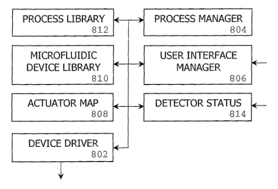
Figure 8 is a diagram illustrating software executed by the computer
102 and the controller 106. The controller 106 executes a device driver 802 to
provide control signals and drive voltages to the actuator system 108 in
response to
a processor manager 804 executed by the computer 102. The process manager 804
includes routines for controlling fluidic operations by the microfluidic
device 110.
When a process is requested, the process manager 804 controls the controller
106
via the device driver 802 to perform a sequence of events associated with the
requested process. The process may include cell washing, or cell detachment. A
process may include selectable subprocesses, such as a cell wash may include a
-15-
CA 02582370 2007-03-29
WO 2007/015703 PCT/US2005/035175
subprocess for washing using PBS. In another embodiment, the process manager
804 executes the text editor described above. In this embodiment, the user may
control processes on the device 110 that are not in the library, or may add
the
process to the software.
A user interface manager 806 controls information communicated
with the process manager 804 displayed to a user on the user interface 104 and
received from the user via the user interface 104. The user may select
processes,
timing of the processes, materials used in the processes and other features of
the
fluidic operations.
An actuator map 808 includes locations, functions, characteristics and
operational parameters of the actuators of the actuator system 108. Figure 17
illustrates an example of the actuator map 808. A microfluidic device library
810
includes locations, functions, characteristics, interconnections, and
operational
parameters of channels, valves, pumps and other elements of the microfluidic
device
110. The microfluidic device library 810 may include dimensions and shapes of
channels, flow rate characteristics of the channels, which may depend on fluid
type,
and valve information, such as location and flow regulation characteristics.
Figure
15 illustrates an example of the microfluidic device library 810. A process
library
812 may include process objects that relate process characteristics to
elements of the
microfluidic device 110. For example, a peristaltic process may correspond to
three
valves with a defined opening and closing sequence and timing based on
d'unensions
and fluid type. The process library 812 may include environmental change
processes, which may be used to mimic in vivo culture for cell cultures or
embryo
growth. These processes may be substance related and may include changing the
concentrations of nutrients, growth factors or vitamins, changing pH, changing
the
presence or absence of materials, such as growth inhibitors. The processes may
be
flow related and may include changes in flow rates or periodic fluctuations of
fluid
flow. Figure 16 illustrates an example of the process library 812.
The process manager 804 uses the microfluidic device library 810 and
the actuator map 808 to associate pins in the actuator system 108 with
channels,
-16-
CA 02582370 2007-03-29
WO 2007/015703 PCT/US2005/035175
valves and other elements of the microfluidic device 110. The process manager
804
determines the pressure or force used by the actuator system 108 to cause an
associated element to perform various operations in the microfluidic device
110.
A detector status module 814 processes and stores data received from
the sensors in the actuator system 108 (not shown) and the sensors 112 (see
Figure
1) in the microfluidic device 110.
As an illustrative example of peristaltic pump formed by three pins
engaging the microfluidic device 110, the process manager 804 applies a
pattern,
such as XXO, OXX, OOX, XOX in repetition, where X is a closed position and 0
is an open position, to pump fluid in a channel. The resultant fluid flow is
pulsatile,
with transient movements in both directions. The net movement can be predicted
by its linear relationship to the pattern change frequency, and flow direction
can be
switched by reversing the pattern of actuation.
Figure 9 is a flow chart illustrating operation of the software of
Figure 8. The user interface manager 806 receives device information and bio
information (block 902) and stores the information in the microfluidic device
library
810 and actuator map 808. The device information includes the location and
type
of elements of the microfluidic device 110 and the location and type of
actuators in
the actuator system 108. The user interface manager 806 receives process
requests
(such as pump, mix, crush or others described herein) from the user for
processes
to be executed on the microfluidic device 110 (block 904). The process manager
804 retrieves the corresponding process from the process library 812 (block
906)
and determines the operational parameters for performing the process (block
908),
which are provided to the device driver 802. The process manager 804
determines
the processes to be applied at various locations in the microfluidic device
110 based
on the microfluidic device library 810, and relates the processes and
locations to
actuators in the actuator system 108 using the actuator map 808. The device
driver
802 determines control signals and timing (block 910) by generating software
objects shown in Fig.10 according to the retrieved processes the parameters
described above. The software objects provide the control signals and voltages
to
-17-
CA 02582370 2007-03-29
WO 2007/015703 PCT/US2005/035175
the actuator system 108 by messagings shown in Fig. 11-14 (block 912). The
detector status module 814 receives information from the detectors 112 of the
state
and status of the microfluidic device 110 (block 914). In response to the
detector
status, the process manager 804 executes feedback control (block 916) on the
application of control signals to the devices (block 912). If the user has
selected
other processes (block 918), the process manager 804 retrieves the next
corresponding object (block 906) and proceeds as described above. Otherwise,
the
process manager 804 determines whether another user selection is being made
(block 920). If an additional selection is made, the user interface manager
806
receives the process request (block 904) and the process manager 804 proceeds
as
described above. Otherwise, the process ends (block 922).
In the illustrative example of Figure 9, each element of software is
described as being performed either the computer 102 or the controller 106,
but may
be performed by the other in other embodiments.
In one embodiment, the software operates based on a two-dimensional
dot matrix configuration of the actuators of the actuator system 108. As used
herein, the dots correspond to an actuator. The actuators in the matrix deform
the
elastomer microchannels to configure particular routes and flow rates. The
software
is described based on this configuration, but other configurations may be
used.
Figure 10 is a diagram illustrating software objects generated by the
process manager 804 to control the device. A timed/keyed dot state object 1002
defines user selected states of dots and timing of changes in the state of
dots. A key
state object 1004 sets references to the dots that are to be activated or
deactivated
by user input, such as key pressing, and sets references to the key states
based on
the object 1004 and a timeline object 1006.
The timeline object 1006 functions as a clock counter and refers to
dots to be activated or deactivated after specified time periods. A timed dot
state
object 1008 functions as a clock counter and refers to dots to be activated
after a
specified wait period. A dot state object 1010 includes position and status
(e.g., up
-18-
CA 02582370 2007-03-29
WO 2007/015703 PCT/US2005/035175
or down) of dots and generates write states for a hardware wrapper object
1012.
The device driver may use the hardware wrapper object 1012 for execution. The
hardware wrapper object 1012 includes dot matrix location and a matrix buffer
for
storing data sent to the actuator system 108.
The process manager 804 controls the hardware by generating
instances of the state machine drives of desired patterns in the object 1002
for the
objects 1004 and 1008. The object 1010 passes messages to the hardware wrapper
object 1012, e.g., each clock cycle, to change the state of the actuator
system 108.
The objects described for Figures 11-14 are described in terms of one
or two dots or actuators, but may be generalized into objects covering all
actuators,
or into objects for each actuator, depending on software implementation, but
not
limiting to the present invention.
Figure 11 is a diagram illustrating a timing sequence for the dot state
object 1010. The process manager 804 generates a control signal 1101 for the
dot
state object 1010 to set the position and state of the actuators (event 1102).
In
response to the control signal 1101, the dot state object 1010 generates the
write
states for the hardware wrapper 1012, which may be the device driver 802
executed
by the controller 106 (event 1104). The hardware wrapper 1012 sends buffer
data,
which includes control signals and voltages for corresponding pins, to the
actuator
system 108 (event 1106).
Figure 12 is a diagram illustrating a timing sequence for a two timed
dot state object of the software of Figure 10. The process manager 804
generates
a control signal 1201 for two timed dot state objects 1008A and 1008B to set
the
wait time to an action, a duration of the action and a next state for objects
1008A
and 1008B for the actuators (event 1202). With clock signals from a clock
handler,
the timed dot state object 1008A sets writes states (event 1204A) for the
hardware
wrapper 1012 to send data to the buffer (events 1208A and 1208B) and to start
the
timed dot state object 1008B (event 1206). The timed dot state object 1008B
sets
write states for the hardware wrapper 1012 (events 1208C and 1208D) and starts
the
-19-
CA 02582370 2007-03-29
WO 2007/015703 PCT/US2005/035175
timed dot state object 1008A to set a write state (event 1204B) and set the
write
states for the hardware wrapper 1012 (event 1208E).
Figure 13 is a diagram illustrating a timing sequence for a key state
object of the software of Figure 10. The process manager 804 generates a
control
signal 1301 for two key state objects 1004P and 1004S to set activation state
for an
actuator upon the next key state or deactivation state for the actuator upon
the next
key state for objects 1004P and 1004S, respectively (event 1302). The key
handler
provides the key state (event 1304A) that starts the timed dot state 1008
(event
1308), and sets the key state object 1004S for responding to deactivate key
state in
response to the key state object 1004P. The key handler provides the key state
for
the deactivation by the key state object 1004S (event 1306) that stops the
timed dot
state 1008 (event 1308).
Figure 14 is a diagram illustrating a timing sequence for a timeline
object of the software of Figure 10. The process manager 804 generates a
control
signal 1301 for the timeline object 1006 for controlling timed dot state
objects
1008V and 1008P. Durations are set for the timed dot state objects 1008V and
1008P (event 1402) with the timeline object 1006 controlling the start of the
states
(event 1402) using the time handler. The activation or deactivation of the
timed dot
states 1008V and 1008P are stopped after the set duration (events 1406 and
1408,
respectively) using the time handler.
By use of the present invention, numerous functions can be
implemented on a single device. Use of multiple reservoirs for supply of
nutrients,
growth factors, and the like is possible. The various reservoirs make possible
any
combination of fluid supply, e. g. , from a single reservoir at a time, or
from any
combination of reservoirs. This is accomplished by establishing fluid
communication with a reservoir by means of a valved microchannel, as
previously
described. By progranmiing the actuator system 108, each individual reservoir
may
be connected with a growth channel or chamber at will. By also incorporating a
plurality of extendable protrusions along a microchannel supply, peristaltic
pumping
may be performed at a variety of flow rates. Uneven, pulsed flow typical of
-20-
CA 02582370 2007-03-29
WO 2007/015703 PCT/US2005/035175
vertebrate circulatory systems can easily be created. Combinatorial, regulated
flow
with multiple pumps and valves that offer more flexibility in microfluidic
cell
studies are created by using a grid of tiny actuators on refreshable Braille
displays
and executed automatically by software in response to user selections of
processes
to be performed.
Upon reading this disclosure, those of skill in the art will appreciate
still additional alternative structural and functional designs for a system
and a
process for controlling fluid operations in a microfluidic device through the
disclosed principles herein. Thus, while particular embodiments and
applications
have been illustrated and described, it is to be understood that the present
invention
is not limited to the precise construction and components disclosed herein and
that
various modifications, changes and variations which will be apparent to those
skilled
in the art may be made in the arrangement, operation and details of the method
and
apparatus of the present invention disclosed herein without departing from the
spirit
and scope of the invention as defined in the appended claims.
-21-