Note: Descriptions are shown in the official language in which they were submitted.
CA 02582439 2007-04-04
WO 2006/037323 PCT/DK2005/000362
Method for recovery of carbon dioxide from a gas
The present invention relates to a method for
recovery of carbon dioxide from a gas and uses
thereof. More particular, the present invention re-
lates to a two-step method for recovery of carbon di-
oxide by condensation at a temperature close to but
above the triple point of carbon dioxide and a subse-
quent absorption of the gaseous carbon dioxide, which
were not liquefied during condensation. The present
invention also relates to a plant for the recovery of
carbon dioxide from a gas.
Background of the invention
Carbon dioxide is a well-known gas, which is
present in the atmosphere. It is released to the at-
mosphere in large amounts by fermentation processes,
limestone calcination, and all forms of combustion
processes of carbon and carbon compounds. In the re-
cent decades, the attention in respect of said emis-
sion has been rising, because of the environmental
problem due to future climate change via Greenhouse
effect. Consequently, extensive work has been per-
formed over the years in order to develop processes
for the removal of carbon dioxide from combustion
gases. If possible, a subsequent recovery of carbon
dioxide may make those processes economical feasible.
Various methods for removal of a gaseous compo-
nent from a gas stream are known in the art. Espe-
cially, absorption has been mentioned as a suitable
method for removal of components from gaseous waste
CA 02582439 2007-04-04
WO 2006/037323 PCT/DK2005/000362
2
streams. In US 3,266,220 it was proposed to remove
carbon dioxide from gaseous mixtures by the utiliza-
tion of solvents having a selective solubility of
carbon dioxide. As examples of selective solvents are
mentioned water, methyl alcohol, acetone and propyl-
ene carbonate.
It is well-known that the triple point for pure
carbon dioxide is situated at -56.6 C and 5.2 bar.
This means that carbon dioxide cannot be found as a
liquid at atmospheric pressure irrespective of the
temperature. In order to obtain a liquid a tempera-
ture above -56.6 C and a pressure of at least 5.2 bar
must be applied.
A method for liquefaction of carbon dioxide
from fermentation of. alcohol or from other gas
sources by condensation following compression is dis-
closed in European patent application EP 1308502. In
this method, the condensation takes place preferably
at -20 C to -55 C and at a pressure in the range of
19-20 bar. However, no further effort for recovery of
uncondensed carbon dioxide is mentioned in said
script.
The object of the present invention is to pro-
vide a method for recovery of carbon dioxide from a
C02-containing gas.
Surprisingly, the present inventor has found
that an improved method for recovery of carbon diox-
ide from a gas may be obtained by a novel two-step
method. By combining an initial condensation of the
gas to be treated with a subsequent absorption of the
gaseous carbon dioxide, which did not condense in the
first step, it is possible to recover carbon dioxide
CA 02582439 2012-09-04
3
at much higher yields than known in the art and in a
financially more feasible way.
Brief description of the drawings
Fig. 1 is a block diagram of a plant for
performing the recovery of carbon dioxide from a gas
stream in accordance with the invention.
Fig.2 is a block diagram of an alternative
plant for performing the recovery of carbon dioxide
from a gas stream in accordance with the invention.
Description of the invention
The present invention relates to a method for
recovery of carbon dioxide from a gas, use of said
method, and a plant for recovery of carbon dioxide
from a gas.
The method according to the present invention
comprises the steps of:
a. feeding a plant with a pressurised C02-containing
gas and/or compressing the C02-containing gas
during feeding,
b. cooling the compressed gas obtained in step a,
c. separating the gas obtained in step b by use of a
condensation procedure, by which said gas is
separated into a C02-rich liquid (L1), in which
the content of liquid 002 is at least 95 weight-%,
and a 002-containing gas (G1),
d. absorbing the gas Gl obtained in step c by means
of an absorbing agent, by which the gas G1 is
CA 02582439 2012-09-04
3a
separated into a liquid (L2) and a C02-poor gas
(G2),
e. separating the liquid L2 obtained in step d in
order to obtain a C02-containing gas (G3) and a
liquid (L3),
f. compressing the gas G3 obtained in step e in order
to obtain a C02-containing gas (G4), and
g. distilling the liquid L1 obtained in step c and
the gas G4 obtained in step f in order to recover
liquid CO2 (L5) and a gas (G5) substantially free
of C02-
In the method according to the invention, the
carbon dioxide is recovered substantially in two
steps. Initially, carbon dioxide is recovered by
condensation of the compressed and cooled feed gas.
After this gas/liquid separation, the carbon dioxide
left in the gas stream is recovered by subjecting
CA 02582439 2007-04-04
WO 2006/037323 PCT/DK2005/000362
4
said gas stream to an absorption procedure, by which
the carbon dioxide present in the gas is absorbed by
means of an absorbing agent.. Subsequent separation of
the carbon dioxide and the absorbing agent yields a
second crop of carbon dioxide.
In the first step (step a) of the method ac-
cording to the present invention a pressure is ap-
plied to the feeding gas unless the gas is already at
a sufficient elevated pressure prior to feeding. In a
preferred embodiment the gas is pressurised during
feeding in such a way that the pressure is at least
bar. Alternatively, the gas entering the plant is
at an elevated pressure of at least 20 bar.
The concentration of carbon dioxide in the feed
15 gas will depend on the origin of said gas. However,
in- a preferred embodiment, the concentration of car-
bon dioxide is at least 40 % v/v, more preferred at
least 45 % v/v, and even more preferred at least 50
v/v.
20 In step b of the method according to the inven-
tion the compressed gas is cooled until an appropri-
ate temperature has been reached. As mentioned above
it is preferred that the temperature is kept above
the triple point at -56.6 C. In a preferred embodiment
the gas is cooled until a temperature below -20 C has
been reached. This cooling may be performed in one or
more steps. For a person skilled in the art such
mathematical calculations in respect of the number
and the size of heat exchangers needed in order to
optimise the process for this cooling are standard
procedure.
The gas, which is now present at an elevated
CA 02582439 2007-04-04
WO 2006/037323 PCT/DK2005/000362
pressure and a decreased temperature, is separated in
step c by use of a condensation procedure into a C02-
rich liquid (L1) and a C02-containing gas (Gi). In a
preferred embodiment, said condensation procedure is
5 a flash distillation. By the term "C02-rich liquid" as
used herein is meant a liquid phase, wherein the con-
tent of liquid CO2 is at least 95 weight-%, more pre-
ferred at least 97 weight-%, even more preferred at
least 98.5 weight-%.
When performing this flash distillation it is
necessary to control the temperature and the pressure
in order to ensure condensation of carbon dioxide and
in order to prevent deposit of solid carbon dioxide.
Preferably, the. flash distillation is performed at a
pressure by which condensation of 50 to 65 % of the
carbon dioxide in the gas is recovered.
In a preferred embodiment of the present inven-
tion the temperature of the C02-containing gas G1
leaving the flash distillation column is in the range
of -30 C to -70 C, more preferred from -44.1 C to
-56 C, even more preferred from -46.1 C to -50.1 C,
most preferred from -47.6 C to -48.6 C, and the pres-
sure of said gas is in the range of 10 bar to 200
-bar, more preferred from 12 bar to 50 bar, even more
preferred from 20 bar to 40 bar, most preferred from
28 bar to 32 bar. The temperature of the liquid L1
leaving the flash distillation column is in the range
of -30 C to -55 C, more preferred from -45 C to -53 C,
even more preferred from -47 C to -51 C, most pre-
ferred from -48.5 C to -49.5 C, and the pressure of
said liquid is in the range of 10 bar to 200 bar,
more preferred from 14 bar to 27 bar, more preferred
CA 02582439 2012-09-04
6
from 16 bar to 22 bar, most preferred from 17.5 bar
to 18.5 bar.
Alternatively, the liquid stream L1 may be
cooled to a temperature below -55 C causing the carbon
dioxide to solidify, and consequently removing the
product of carbon dioxide from the plant as solid dry
ice.
In said flash distillation step more than half
of the amount of the carbon dioxide present is recov-
ered in the C02-rich liquid. However, a considerable
amount of carbon dioxide is leaving the flash distil-
lation column in the cold gas stream Gl. In order to
recover said considerable amount of carbon dioxide
the cold gas stream Gi is passed through an absorp-
tion column in step d.
In the absorption column the gas G1 is sepa-
rated into a liquid (L2) containing the major part
(that is more than 90%) of the carbon dioxide enter-
ing the absorption column and a C02-poor gas (G2). By
the term "CO2-poor gas" as used herein is meant a gas,
in which the partial pressure of carbon dioxide is
less than 3 bar, preferably less than 1.5 bar, more
preferred less than 1 bar.
The absorbing agent used for absorption of
gaseous carbon dioxide may be any solvent known to be
able to absorb carbon dioxide. However, it is pre-
ferred to use an absorbing agent causing a physical
absorption, rather than a chemical absorption, of
carbon dioxide due to the lower energy consumption
needed for the subsequent separation of carbon diox-
ide from the absorption agent. Examples of preferred
absorbing agents are SELEXOL;M methanol, and propylene
CA 02582439 2012-09-04
7
carbonate. At present, the most preferred absorbing
agent is methanol. This is due to the fact that the
absorption properties of methanol increase. with de-
creasing temperature. Consequently, no heating of the
cold gas G1 is required prior to the absorption step.
Furthermore, the energy requirement in the subsequent
flash distillation is minimised.
The temperature of the liquid L2, when leaving
the absorption column, depends on the absorbing agent
used. When methanol is used as absorbing agent the
temperature of methanol entering the absorption col-
umn is in the range of -44 C to -52 C, more preferred
from -46 C to -50 C, and even more preferred around
-48 C. However, when SELEXOLTMis used as the absorption
agent, the temperature of SELEXOLTMwhen entering the
absorption column is in the range of 0 C to 10 C, more
preferred from 2 C to 8 C, and even more preferred
from 4 C to 6 C.
This difference is due to the fact that the
viscosity of SELEXO1Pincreases as the temperature de-
creases. At a temperature below about 0 C the viscos-
ity of SELEXOLMhas reached a level, where the hand-
ling of the liquid becomes difficult. Consequently,
when SELEXOLTMis used as the absorbing agent, the tem-
perature must be kept at a temperature equal to or
above 0 C. Furthermore, it will be necessary to warm
up the gas stream G1 before said stream enters the
absorption column. It is within the knowledge of a
person skilled in the art to determine an appropriate
temperature of any usable absorbing agent entering
the absorption column when the physical properties of
CA 02582439 2007-04-04
WO 2006/037323 PCT/DK2005/000362
8
said absorbing agent is known.
In cases where the absorbing agent is methanol
the temperature of the liquid L2 is in the range of
-23.7 C to -31.7 C, more preferred from -25.7 C to
-29.7 C, most preferred from -27.2 C to -28.2 C, and
the pressure of said liquid is in the range of 26 bar
to 50 bar, more preferred from 28 bar to 45 bar, most
preferred from 29.5 bar to 30.5 bar.
In cases where the absorbing agent is SELEXOL
the temperature of the liquid L2 is in the range 5 C
to 20 C, more preferred from 10 C to 17 C, even more
preferred in the range of 12 C to 15 C.
In order to separate the carbon dioxide from
the absorbing agent the liquid (L2) is preferably
flash distilled in the subsequent step e of the proc-
ess according to the invention. This separation may
be performed in one or more consecutive flash-
distillation columns. Furthermore, the flash distil-
lation may be performed as a low pressure process or
as a high pressure process or a combination of both.
It is within the knowledge of a skilled person to
combine the number, size and type of flash distilla-
tion columns in order to obtain the combination most
feasible.
In cases where methanol is used as the absorb-
ing agent in step d, the temperature of the C02-
containing gas G3 when leaving the flash distillation
column is in the range of -23.5 C to -33.5 C, more
preferred from -25.5 C to -31.5 C, most preferred from
-27.5 C to -29.5 C. The pressure of said gas is in the
range of 5 bar to 20 bar in cases where the gas G3 is
CA 02582439 2007-04-04
WO 2006/037323 PCT/DK2005/000362
9
leaving a high pressure column and in the range of a
negative pressure of 0.5 bar to a pressure of 3 bar
when leaving a low pressure column.
The gas leaving the flash distillation col-
umn(s) is subsequently compressed (step f) . It is
standard procedure for a skilled person to determine
the number and size of compressors necessary in order
to perform this compression step in the most suitable
way. If more than one flash distillation column is
used, the gas leaving each column may be compressed
separately before mixing. Alternatively, the gases
leaving each column may be mixed before compressing.
In cases where methanol is used as the absorb-
ing agent, the temperature of the gas G4, when enter-
ing the distillation column, is in the range of -44 C
to -52 C, more preferred from -46 C to -50 C, most
preferred from -47.5 C to -48.5 C, and the pressure of
said liquid is in the range of 14 bar to 22 bar, more
preferred from 16 bar to 20 bar, most preferred from
17.5 bar 18.5 bar.
Almost every gas produced in combustion proc-
esses contains water to some extent. If water is pre-
sent in the gas to be treated by the method according
-to the present invention it must be removed in.order
to prevent deposit of solid water in the plant. Con-
sequently, in a preferred embodiment of the invention
water is removed before cooling of the gas in step b.
The water is preferably removed to such an extent
that the pressure dew point of water is below -55 C.
The various methods for removing water from
gases lies within the knowledge of a person skilled
in the art, who easily may determine the most suit-
CA 02582439 2007-04-04
WO 2006/037323 PCT/DK2005/000362
able method, which depends on the chemical composi-
tion of the gas to be treated. Examples of such meth-
ods are adsorption with molecular sieves, silica gel,
activated alumina and other absorbents suitable for
5 dehydration to a low water dew point.
The liquid L3 leaving the flash distillation
column(s) in step e is substantially composed of ab-
sorbing agent, wherein a low concentration of carbon
dioxide is present. If no reuse of the absorbing
10 agent is provided for, large amounts of absorbing
agent must be disposed of. Thus, in a preferred em-
bodiment said liquid is re-circulated to the absorp-
tion column. As a result, the waste of absorbing
agent is reduced significantly and the recovery of
carbon dioxide is increased.
The gas G4 contains absorbing agent in small
amounts when entering the distillation column if no
special effort for removing this impurity has been
made. Therefore, in a preferred embodiment the traces
of absorbing agent are removed from the liquid ob-
tained in step f by a filtration method.
A person skilled in the art would know how to
perform this filtration in the most suitable way de-
-pending on the chemical composition, the temperature,
and the pressure of the gas G4 leaving the compres-
sors in step f. Examples of suitable methods are ad-
sorption with molecular sieves, silica gel, activated
alumina, activated carbon and other absorbents suit-
able for removal of organic compounds from carbon di-
oxide gases.
The liquid Li and the gas G4 obtained in step c
and step f, respectively, may be distilled in order
to purify the liquid carbon dioxide. Said two streams
CA 02582439 2007-04-04
WO 2006/037323 PCT/DK2005/000362
11
may be mixed inside the distillation column, or they
may be distilled separately, and then mixed before
storage. If filtration of the gas G4 as described
above is included in the method this filtration step
takes place prior to the distillation.
In the method according to the present inven-
tion the gases G2 and G5 obtained from the absorption
column in step d and the above-mentioned distillation
column(s) respectively, are either recycled or is
disposed of by burning. In a preferred embodiment
said gases are expanded prior to burning in order to
recover energy.
The purity of the liquid carbon dioxide L5
leaving the distillation column(s) will depend on the
process parameters in each step of the method. Condi-
tional upon the subsequent use of the product differ-
ent grades of purity is required. If, for example,
the subsequent use is the incorporation of carbon di-
oxide as a component in a food product, the liquid
carbon dioxide must be substantially absolute pure.
By contrast, if the subsequent use is in a fire ex-
tinguisher the requirements towards purity is less
stringent. However, in a preferred embodiment the
product is at least 99.5% pure.
Examples of preferred uses of the produced liq-
uid carbon dioxide are the incorporation as a food
grade component in soft drinks and other food prod-
ucts.
Carbon dioxide may be recovered from all kinds
of gases. In general, all gases with a partial pres-
sure of carbon dioxide above a certain value in order
for the carbon dioxide to be condensed and in a mix-
ture of components, which after condensation may be
CA 02582439 2007-04-04
WO 2006/037323 PCT/DK2005/000362
12
separated by distillation, can be treated in the
method according to the present invention. However,
it is an object of the. present invention to use the
present method for the recovery of carbon dioxide
from a gas coming from a plant for the manufacture of
hydrogen or for the manufacture of Syngas.
In the most preferred embodiment the feeding
C02-containing gas is a waste gas originating from a
plant for the manufacture of hydrogen and the gases
G2 and G5 is recycled to said plant for manufacture
of hydrogen.
The present invention also relates to a plant
for the recovery of carbon dioxide from a gas stream.
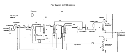
Such a plant (shown in the form of a flow diagram in
figure 1) comprises optionally a compressor (A) con-
nected to a cooling unit (B), said cooling unit being
connected to a condensation unit (C) having a gas
outlet and a liquid outlet, the gas outlet of said
condensation unit (C) being connected to an absorp-
tion column (D) with a gas outlet and a liquid out-
let, said outlet for liquid being connected to one or
more consecutive separation units (E) each having a
gas outlet and a liquid outlet, the gas outlets of
-said separation units (E) , being connected to one or
more compressors (F), and the outlet of said compres-
sor(s) (F) and the outlet of the liquid outlet from
the condensation unit (C) optionally being connected
to one or more distillation columns (G).
The compressors A and F, respectively, may be
any kind of compressor suitable for compressing the
gas to be treated. As examples of suitable compres-
sors, centrifugal, screw, and reciprocating compres-
sors may be mentioned. Especially preferred compres-
CA 02582439 2007-04-04
WO 2006/037323 PCT/DK2005/000362
13
sors are those having high polytropic efficiency and
thereby low power consumption.
The cooling unit B-may be any kind of refrig-
erator capable of cooling a pressurised gas. A person
skilled in the art can easily select a suitable cool-
ing unit dependent on the required temperature to be
reached and the chemical composition of the gas to be
treated.
The condensation unit (C) and the separation
unit(s) (E) are preferably flash distillation col-
umns. Said columns may be any kind of flash distilla-
tion columns known in the art. A skilled person may
easily determine whether one or more high pressure
flash distillation column(s) or one or more low pres-
sure distillation column(s) or a. combination thereof
is needed in order to obtain the result required in
each step. It will also be within the knowledge of
the skilled person to determine whether the desired
result is achieved most suitable by using only one
column, or by using two or more columns connected in
series or in parallel.
The absorption column (D) to be used may be any
column known in the art suitable for the performance
.of absorbing gaseous carbon dioxide into an absorbing
agent. The most suitable absorption columns to be
used are normally packed columns with a low pressure
drop, but also trayed columns may be employed.
In a preferred embodiment the plant comprises a
dehydrator in order to remove water from the gaseous
stream. The process of dehydrating a gaseous stream
is well-known in the art, and a suitable dehydrator
to perform the dehydration is easily selected by the
skilled person. However, dehydration units TSA ad-
CA 02582439 2007-04-04
WO 2006/037323 PCT/DK2005/000362
14
sorber with molecular sieves are preferably employed.
In yet another preferred embodiment the plant
according to the present invention further comprises
a filter for removal of traces of absorbing agent. It
is within the knowledge of a skilled person to select
the most appropriate kind of filter when the parame-
ters such as type of absorbing agent as well as the
temperature and pressure of the liquid to be fil-
trated are known. Examples of preferred filters are
filter units TSA adsorber with molecular sieves or
activated carbon.
The distillation column(s) (G) may be any kind
of column known in the art suitable for distilling
liquid carbon dioxide. The most suitable distillation
columns to be used are normally packed columns with a
low pressure drop, but also trayed columns maybe em-
ployed.
As mentioned above, the gases G2 and G5 may be
expanded before they are disposed of by burning in
order to recover energy. Actually, an energy recovery
about of 8-10% is possible. Consequently, a preferred
embodiment is directed to the plant comprising an ex-
pander for this purpose. A turbo expander, for gener-
ating electrical energy or direct compression is an
example of a suitable expander, which may be used in
the plant.
It is within the standard procedure of a
skilled person to calculate the numbers and sizes of
each of the above-mentioned units of the plant when
the mass flow, the chemical composition, the tempera-
ture, and the pressure of each stream is known in or-
der to obtain the most feasible mode of operating the
plant.
CA 02582439 2007-04-04
WO 2006/037323 PCT/DK2005/000362
When selecting suitable materials for each of
said units, special consideration must be directed to
the temperature, the pressure, .and the chemical and
physical properties of the gases and liquids to be
5 treated. However, such consideration will be within
the knowledge of a person skilled in the art.
Furthermore, a skilled person can easily ac-
knowledge that the selection and control of process
parameters will depend on the chemical composition of
10 the gas entering the plant as well as the chemical
composition and physical condition of the gases and
liquids in each step of the method. Calculations for
determining the number and size of heat exchangers in
order to minimize the energy consumption for cooling
15 is standard -procedure for a person skilled in the
art.
An alternative plant for performing the recov-
ery of carbon dioxide from a gas stream according to
the present invention is shown in figure 2.
The plant shown in figure 2 differs from the
plant shown in figure 1 in the way that no distilla-
tion of the gas stream G4 occurs, and that said gas
stream G4 is recycled and mixed with the pressurised
-feeding stream prior to the optional dehydrator unit.
Also the gas stream G5 leaving the distillation col-
umn G' is recycled and mixed with the pressurised
feeding stream after the optional dehydrator unit.
Furthermore, the gas stream G2 is recycled. In a pre-
ferred embodiment the gas stream G2 is recycled to
the plant for the manufacture of hydrogen.
In the following the invention is described in
more detail with reference to a preferred embodiment
and to figure 1. Said figure depicts a schematic flow
CA 02582439 2007-04-04
WO 2006/037323 PCT/DK2005/000362
16
diagram for the CO2 recovery according to the present
invention.
Data with respect to pressure and temperature
as well as the composition of the major chemical com-
ponents are given in the table below. All references
to pressures are to the total pressure.
CA 02582439 2007-04-04
WO 2006/037323 PCT/DK2005/000362
17
Table. Physical and chemical properties of
selected gas and liquid streams.
Pressure Temp. CO2. water methane methanol
(bar) ( CY (kg/h) (kg/h) (kg/h) (kg/h)
Feed gas 1.3 30 26760 163 2568 n.d.
gas entering the 31 10 26760 10 2568 n.d.
dehydrator
gas entering 30 -39 26760 n.d. 2568 n.d.
column (C)
gas leaving col- 30 -48 12382 n.d. 2451 n.d.
umn (C) (Gl)
liquid leaving 18 -49 14378 n.d. 118 n.d.
column (C) (Ll)
gas leaving col- 18 -50 919 n.d. 2177 1
umn (D) (G2)
liquid leaving 30 -28 14900 n.d. 274 62561
column (D) (L2)
gas leaving col- 7 -30 1332 n.d. 146 1
umn (E) (G3)
liquid leaving 7 -30 13385 n.d. 81 62560
column (E) (L3)
gas leaving col- 1.2 -45 9868 n.d. 81 7
umn(E') (G31)
gas entering the 23 30 11200 n.d. 226 8
filter
gas entering 18 -49 11043 n.d. 170 n.d.
column (G) (G4)
liquid leaving 18 -29 24578 n.d. n.d. n.d.
column (G+G')
(L5)
gas leaving col- 18 -42 1277 n.d. 294 n.d.
umns (G+G') (G5)
n.d.: not detectable
The gas fed to the plant is a PSA off gas,
which comes from a hydrogen plant. The gas enters the
plant at a temperature of about 30 C, and a pressure
of about 1.3 bar. The mass flow of the feeding stream
is about 34440 kg/hr in total, wherein the mass flow
CA 02582439 2007-04-04
WO 2006/037323 PCT/DK2005/000362
18
of carbon dioxide amounts to 26760 kg/hr. The further
chemical components are water (163 kg/hr), methane
(2568 kg/hr), nitrogen (145 kg/hr), hydrogen (752
kg/hr) ,' and carbon monoxide (4050 kg/hr)
During feeding the gas is compressed in a turbo
compressor. After compression the gas is entering the
dehydrator at a pressure of 31 bar and a temperature
of 10 C, the lower temperature being a result of a
pre-cooling of the compressed gas. In the dehydrator,
which is of the type Activated alumina/molecular
sieve TSA adsorber, water is removed to such an ex-
tent that the content in the gas leaving the dehydra-
tor is not detectable.
In the subsequent step the gas is cooled to a
temperature about -39 C. For this cooling procedure a
refrigeration plant is employed. This refrigeration
plant is a cascade system with C02/NH3 as refrigerant.
The CO2 loop cools to -48 C and the NH3 loop cools to
-29 C.
When entering the flash distillation column (C)
the chemical composition of the compressed and cooled
gas is unchanged compared to the feeding gas except
for the removed of water. The flash distillation col-
umn is a simple knock out drum. As a consequence of
the flash distillation process the carbon dioxide is
divided into a liquid stream (L1) and a gas stream
(G1) .
Liquid carbon dioxide (L1) is leaving the flash
distillation column at a pressure of 18 bar and a
temperature of -49 C with a mass flow of 14378 kg/hr
and only containing traces of methane (118 kg/hr) and
hydrogen, nitrogen, and carbon monoxide in even
CA 02582439 2007-04-04
WO 2006/037323 PCT/DK2005/000362
19
smaller amounts. In the subsequent distillation of
said liquid these traces of impurities are .removed to
such an extent as being non-detectable in the liquid
leaving the column. For this procedure a packed dis-
tillation column (G') is employed.
The mass flow of carbon dioxide in the gas
stream leaving said flash distillation column (C)
amounts to 12382 kg/hr. This carbon dioxide is recov-
ered in a subsequent absorption procedure using
methanol as the absorbing agent. More precisely, the
absorbing agent is a grade AA methanol having a water
content of 0.1 The absorption column (D) is a
packed column. The carbon dioxide is leaving the ab-
sorption column either in the gas phase (G2) or as an
absorbed component in the liquid phase (L2).
The gas phase (G2) is leaving the column (D) at
a pressure of 18 bar and a temperature of -50 C. The
mass flow of carbon dioxide in the gas phase is only
919 kg/hr, while the mass flow of methane is 2177
kg/hr. The liquid phase (L2) is leaving the column
(D) at a pressure of 30 bar and a temperature -28 C.
The mass flow of carbon dioxide in the liquid phase
leaving said column is 14900 kg/hr. Also a consider-
able amount of methane (274 kg/hr) is to be found in
said liquid phase.
The liquid phase L2 is subsequently flash dis-
tilled in two consecutive flash distillation columns.
The first column (E) is a high pressure column and
the second column (E') is a low pressure column. In
the high pressure column carbon dioxide is flashed at
elevated pressure to recover carbon dioxide to the
inter stage pressure of the compressor, and hereby
CA 02582439 2007-04-04
WO 2006/037323 PCT/DK2005/000362
minimising the energy consumption. This column is a
packed column. The residual carbon dioxide is recov-
ered by flashing at a lower pressure. Further, the
solvent is re-boiled to ensure a high recovery of
5 carbon dioxide at the top of the absorber and thereby
ensure low residual carbon dioxide in the liquid. It
is also possible to use a vacuum flash in order to
further reduce the amount of carbon dioxide in the
liquid.
10 The pressure and the temperature of the gas G3
as well as of the liquid L3 leaving the high pressure
flash column is 7 bar and -30 C, respectively. The
mass flows are given in the table. The liquid phase
L3 is passed on to the low pressure flash distilla-
15 tion column (E'). The pressure and the temperature of
the gas (G31) leaving the low pressure column is 1.2
bar and -45 C. The liquid phase leaving the low pres-
sure column is recycled to the absorption column in
order to reuse the methanol. At the same time the
20 carbon dioxide left in said liquid phase is not
wasted but returned to the absorption column.
The gas stream leaving the low pressure column
is compressed before mixed with the gas stream leav-
ing the high pressure column. Subsequently the mix-
ture of said two gases is further compressed in order
to obtain a pressure of 23 bar at a temperature of
C before said mixture is entering the filtration
unit in order to remove traces of methanol. Actually,
in this preferred embodiment the concentration of
30 methanol is decreased to such an extent that it can-
not be detected in the stream leaving the filtration
unit. A molecular sieve TSA adsorber is used as fil-
CA 02582439 2007-04-04
WO 2006/037323 PCT/DK2005/000362
21
ter, while the compressors are oil lubricated screw
compressors.
The filtrated liquid stream is passed on to a.
distillation column (G) at a pressure of 18 bar and a-
temperature of -49 C. The liquid leaving this distil-
lation column (G) is mixed with the liquid leaving
the distillation column (G') before storage. The mass
flow of carbon dioxide in this streams (G+G') is
24578 kg/hr and equals the total mass stream as it
does not contain any detectable impurities.
The gases leaving the two distillation columns
are mixed before they are entered into a turbo ex-
pander. Also the gas leaving the absorber G2 is en-
tered into the turbo expander. The gas leaving the
turbo expander is disposed of by burning. The purpose
of expanding said gases is to recover energy. In.this
preferred embodiment an energy recovery of 3 % was
obtained. Cold and hot streams not described are used
for energy minimisation.