Note: Descriptions are shown in the official language in which they were submitted.
CA 02582489 2007-03-20
1
IMPROVED EDGE TRIMMING AND BOARD RIPPING APPARATUS AND
METHOD
BACKGROUND OF THE INVENTION
[0001] Many trees do not grow straight so that the logs cut from the trees are
swept
or curved in shape. Special procedures and equipment must be used to maximize
the
board feet of lumber cut from these imperfect logs. FIGS. 1A and 113
illustrate two
typical swept or curved logs 2, 3. FIG. 2 is an end view of log 2 showing how
the swept
or curved feature is typically in a single plane. To create lumber from log 2,
side boards
4, illustrated in FIG. 3, are, in this typical example, cut from log 2 by
making cuts along
lines 6, 7 on either side of log 2 so that each side board 4 has parallel, cut
surfaces 8, 9
and unfinished, uncut edges 10, 11. These cuts are made in a conventional
manner. What
is left of log 2 is called a center cant illustrated as center cant 12 in FIG.
4.
[0002] Center cant 12 has opposite, parallel, cut surfaces 14, 15 which
correspond to
surfaces 9 of boards 4 made at cutting lines 7. The end 16 of center cant 12
in FIG. 4 has
a number of dashed cut lines 18 corresponding to where cant 12 will be rip
sawn to
create center cant lumber 20. See also FIG. 5. To maximize the board feet of
lumber
from center cant 12, cut lines basically parallel the edges 22 of center cant
12. While the
center cant lumber 20 will originally have the same curved or swept shape as
center cant
12, most, if not all, of this curve can be removed during drying operations.
Side boards 4
are cut differently than center cant 12 to maximize the amount of side board
lumber 24
as suggested in FIG. 6. Using conventional computer-controlled edger
optimizing
systems, the number, size and position of center cant lumber 20 and side board
lumber
24 are determined automatically using appropriate computer programs based upon
profile information of the side board 4 or center cant 12 scanned into the
computer.
[0003] For example, U.S. Pat. No. 4,239,072 discloses a method and apparatus
for
edge trimming a side board. A number of overhead pressure rolls engage the
side board
as the side board passes along a chain conveyor. The side board is centered by
sets of
centering rolls. A number of scanning gates are positioned above the conveyor
to provide
a computer with appropriate information on the profile of the side board. The
edging
CA 02582489 2007-03-20
2
assembly includes a pair of adjustable cutting heads designed to chip the
unwanted edges
from the side board. The cutting heads are slewed in a direction perpendicular
to the
direction of movement of the board by hydraulic cylinders so that one or more
pieces of
side board lumber can be cut from a single side board.
[0004] U.S. Pat. No. 4,449,557, assigned to the same assignee as U.S. Pat. No.
4,239,072, uses substantially the same system for delivering partially cut
logs to an
edging assembly as the '072 patent. However, instead of using angled edge
chippers, as
in the '072 patent, the '557 patent uses sawing disks or saw blades to make
the edge cuts.
The entire edger saw system moves as a unit so that the sawing disks can skew,
that is
change the angle between the axis of rotation of the sawing disks and the
direction of
feed of the work piece and can slew, that is move laterally along a line
generally
perpendicular to the direction of feed of the work piece.
[0005] Some conventional edger optimizer systems measure the boards
transversely
and then position the board onto a feeding mechanism and move the board
longitudinally
into the edger. This conventional method requires a considerable amount of
expensive
scanning, positioning and transporting equipment to carry out the process.
Conventional
systems also commonly create cumulative scanning, positioning and transport
errors that
make the systems somewhat less than optimal. With regard to the '557 patent,
complex
board centering mechanisms, multiple scanner heads, complex and high
maintenance
feeding and tracking devices, and complex high inertia edger rotation devices
are all
characteristic of the system described in the patent.
[0006] U.S. Pat. No. 5,761,979 and No. 5,870,939 describe a saw assembly that
includes a rotatable arbor on which two or more saw blades are mounted. The
driving
interface between the saw blades and the arbor permits the axis of rotation of
the saw
blades to be collinear with the arbor axis or skewed a few degrees in either
direction. A
saw blade positioning assembly includes pairs of guide arms which engage the
sides of
the saw blades to position each saw blade at the proper location along the
arbor and at
the proper skew angle. The guide arms are moved in unison so that the axial
position and
the skew angle of each of the saw blades can be changed in unison before and
during
sawing operations.
[0007] In these designs, the use of guide arms that engage the sides of the
rotating
saw blades, require constant maintenance and can often lead to problems. These
saw
CA 02582489 2010-02-26
3
guide arms require the use of saw blade lubricants and cooling water that
reduce the fuel
value of the saw dust and cause environmental and waste water concerns.
BRIEF SUMMARY OF THE INVENTION
[0008] In a first aspect, the present invention provides a wood cutting
assembly
comprising: a frame; a cutter subassembly supported by the frame and
comprising: a
slewing assembly having a slewing axis; a cutter positioning body secured to
and
movable by the slewing assembly for movement along the slewing axis; a spindle
housing mounted to the cutter positioning body for pivotal movement about a
pivot axis;
a cutter driver; a spindle mounted to the spindle housing for rotation about a
spindle
rotation axis, the spindle connected to and rotatable by the cutter driver;
and a cutter
affixed to and movable with the spindle; and a skewing assembly supported by
the frame
and coupled to the spindle housing and operable to position the spindle
rotation axis to a
selected angular orientation over a range of angular orientations during the
cutting of
wood thereby positioning the cutter at a selected skew angle.
[0009] In some examples the cutter driver comprises a drive source fixedly
secured
to the frame and an extendable length universal joint driveline assembly. In
some
examples of the driveline assembly connects the drive source to the spindle to
transmit
torque to the spindle while allowing both: [lithe spindle rotation axis to
turn at an angle
relative to the drive source, and [2] the spindle to move closer to or further
away from
the drive source.
[0009a] In another aspect, the present invention provides a method for slewing
and
skewing a cutter while the cutter cuts a log moving along a feed path
comprising:
accessing a cutter mounted to and supported by a housing for rotation about a
rotation
axis, the housing pivotally mounted to a cutter positioner for pivotal
movement of the
housing and cutter therewith about a pivot axis; slewing the cutter by
positioning the
housing and cutter therewith along a cutter shift axis, the cutter shift axis
being
transverse to a feed path of a log; skewing the cutter by pivoting the housing
and cutter
therewith about the pivot axis; and rotating the cutter about the rotation
axis.
[0009b] The present invention also provides a method for slewing and skewing a
plurality of cutters while the cutters cut a log moving along a feed path
comprising:
CA 02582489 2009-08-11
3a
slewing a plurality of cutters to positions along at least one cutter shift
axis, the at least
one cutter shift axis being transverse to a feed path of a log, each cutter
mounted to a
housing for rotation of the cutter about a rotation axis with the housing
pivotally
mounted to a cutter positioner for limited pivotal movement of the housing and
cutter
therewith about a pivot axis; skewing the cutters by pivoting the associated
housings and
cutters therewith about the associated pivot axes; and rotating the cutters
about the
associated rotation axes.
[0009c] In a still further aspect, the present invention provides a method for
slewing
and skewing a plurality of sawblades while the sawblades cut a log moving
along a feed
path comprising: separately slewing a plurality of sawblades to positions
along at least
one sawblade shift axis, the at least one sawblade shift axis being transverse
to a feed
path of a log, each sawblade mounted to a housing for rotation of the sawblade
about a
rotation axis with the housing pivotally mounted to a sawblade positioner for
limited
pivotal movement of the housing and sawblade therewith about a pivot axis;
skewing the
sawblades by pivoting the associated housings and sawblades therewith about
the
associated pivot axes, the skewing step being carried out by simultaneously
skewing at
least some of the sawblades using the same skewing positioner; and rotating
the
sawblades about the associated rotation axes using separate drive lines, the
drive lines
connected to the sawblades by drive joints, the drive joints having rotational
centers, the
pivot axes passing through the rotational centers.
[0010] Other features, aspects and advantages of the present invention can be
seen on
review the figures and the detailed description which follow.
CA 02582489 2007-03-20
4
BRIEF DESCRIPTION OF THE DRAWINGS
[0011] FIGS. 1A and 1B are overall views showing two different types of curved
or
swept logs;
[0012] FIG. 2 is an end view of the log of FIG. 1A taken along line 2--2;
[0013] FIG. 3 is an enlarged view showing a side board cut from the log of
FIG. 2;
[0014] FIG. 4 is an enlarged view showing a center cant cut from the log of
FIG. 2;
[0015] FIG. 5 is a simplified top plan view of the center cant of FIG. 4
illustrating
dashed cut lines and the resulting center cant lumber to be cut from the
center cant;
[0016] FIG. 6 is a simplified top plan of the side board of FIG. 3
illustrating the
outlines of side board lumber to be cut from the side board of FIG. 3;
[0017] FIG. 7 is a simplified top plan view of an example of a sawing
apparatus
made according to the invention;
[0018] FIG. 8 is a simplified side view of the apparatus of FIG. 7;
[0019] FIG. 9 is an enlarged side view of the saw assembly of FIG. 8;
[0020] FIGS. 10 and 11 are end and top views of the saw assembly of FIG.9
showing
a set of two saw blade positioner assemblies and associated saw blades at a
first set of
locations and at a zero cant in FIG. 10 and at a 2 cant in FIG. 11;
[0021] FIG. 12 is an enlarged isometric view of the saw blade positioner
assembly of
FIG. 9 together with a saw blade;
[0022] FIGS. 13, 14 and 15 are side, top and end views of the saw blade
positioner of
FIG. 12;
[0023] FIG. 16 is a somewhat simplified cross-sectional view taken along line
16--16
in FIG. 14;
[0024] FIG. 17 is an enlarged cross-sectional view taken along line 17--17 in
FIG.
13;
[0025] Fig. 18 is a top view of saw blade positioner of FIG. 12 showing the
saw
blade at a 2 degree angle;
[0026] Fig. 19 is a top view of saw blade positioner of FIG. 12 showing the
saw
blade at a -2 degree angle;
[0027] FIG. 20 is an isometric view of an assembly of four saw positioner
assemblies
of FIG. 9;
CA 02582489 2007-03-20
[0028] FIG. 21 is a top view of the saw assembly of FIG.9 showing an alternate
drive
assembly for the spindle;
[0029] FIG. 22 is a section view 22-22 of the alternate saw drive assembly
shown in
FIG. 21;
[0030] FIG. 23 is an isometric view of the alternate saw drive assembly
section view
of FIG. 22;
[0031] FIG. 24 and 25 are an isometric and front view of the alternate saw
drive
assembly of FIG. 21 showing a set of four assemblies configured on a frame;
[0032] FIG. 26 is an isometric view of two of the saw assemblies of FIG. 21
with the
saws replaced with chip heads shown removing the opposing sides of a center
cant;
[0033] FIG. 27 is an enlarged view of FIG. 26;
[0034] FIG. 28 is an isometric view of an assembly of six of the saw
positioners of
FIG. 21 with two positioners having the saws replaced with chip heads shown
chipping
and sawing a center cant; and
[0035] FIG. 29 is an isometric view of the saw assembly of FIG. 21 having a
plurality of saw blades cutting a center cant in the vertical plane.
LIST OF REFERENCE NUMERALS
2 Curved Log
3 Curved Log
4 Side Boards
6 Cut Lines
7 Cut Lines
8 Cut Surfaces
9 Cut Surfaces
Uncut Edges
11 Uncut Edges
12 Center Cant
14 Opposite, Parallel, Cut Surfaces
Opposite, Parallel, Cut Surfaces
16 End of Center Cant 12
18 Dashed Cut Lines
CA 02582489 2007-03-20
6
20 Center Cant Lumber
22 Edges of Center Cant 12
24 Side Board Lumber
26 Chipped Face of Cant 12
30 Sawing Apparatus
32 Infeed Assembly
34 Infeed Lug Chain
36 Partially Cut Log
38 Canted Drive Rolls
40 Fence
41 Longitudinal or Forward Direction
42 Lateral or Infeed Direction
44 Scanning Conveyor
46 Scanning Assembly
48 Scanner
50 Controller
52 Cutting Assembly
54 Pressroll Assembly
56 Saw Assembly
58 Driven Feed Chain
60 Pivotal Press Rolls
62 Drum Reman Head
64 Driven Exit Rolls
66 Sawn Lumber
68 Discharge Assembly
70 Paddle Picker Outfeed
72 Saw Blade Positioner Assembly
74 Saw Spindle
75 Saw Blades
76 Saw Positioner
78 Skewing Assembly
80 Saw Blade Slewing Assembly
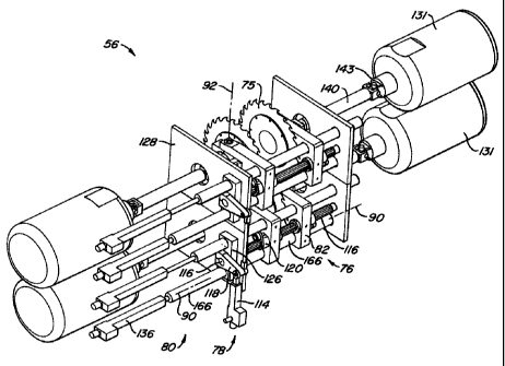
CA 02582489 2007-03-20
7
82 Saw Positioner Body
84 Pivoting Spindle Housing
86 Spindle Bearings
87 Clamping Collar
88 Annular Side Surface of Saw Blade 75
90 Saw Shift Axis
92 Vertical Pivot Axis of 84
93 Pivot Axis of 142
94 Skewing Angle
95 Pivot Axis of 142
96 Pivot Bearings
99 Spindle Rotation Axis
101 Rotation Axis of Fixed Drive Source 131
104 Chip Head
114 Skewing Positioner
116 Skewing Drive Shaft
118 Bell Crank Arm
119 Bell Crank Bushing
120 Sliding Rotary Bell Crank Assembly
121 Thrust Washers
122 End of Skewing Drive Shaft 116
123 Locking Nuts
124 End of Skewing Drive Shaft 116
126 Linear Bearings
128 Saw Assembly Frame
129 One End of Skewing Cylinder 114
130 Steering Arm
131 Fixed Drive Source
132 Skewing Linkage
133 Ball Joint
136 Linear Positioner
140 Extendable Universal Joint Driveline Assembly
CA 02582489 2007-03-20
8
141 Feed Path
142 Universal Joint
143 Universal Joint
144 Slip Joint
150 Packing Nut
151 Lock Nut
152 Internal Splined Drive Flange
153 Drive Flange Adaptor
154 Hollow Shaft of Fixed Drive Source 131
155 Smooth Bore of Hollow Shaft 154
156 Guide Piston
157 Lubrication Port and Fan Mounting Adaptor
160 End Yoke of Slip Joint 144
166 Shift Shaft
DETAILED DESCRIPTION OF THE INVENTION
[0036] The following description will typically be with reference to specific
structural embodiments and methods. It is to be understood that there is no
intention to
limit the invention to the specifically disclosed embodiments and methods but
that the
invention may be practiced using other features, elements, methods and
embodiments.
Preferred embodiments are described to illustrate the present invention, not
to limit its
scope, which is defined by the claims. Those of ordinary skill in the art will
recognize a
variety of equivalent variations on the description that follows. Like
elements in various
embodiments are commonly referred to with like reference numerals.
[0037] The present invention is directed to a wood product assembly, such as
an
improved edge trimming and board ripping apparatus, and method which provides
a
greatly simplified approach to, for example, optimally edging and ripping
boards.
[0038] The edge trimming and board ripping apparatus includes an improved saw
assembly used as a part of a sawing apparatus. The sawing apparatus, in one
example,
includes an in-feed assembly which delivers side boards or center cants one at
a time to a
scanning assembly. The side boards and center cants both have two parallel cut
surfaces
and are referred to generically as partially cut logs, cut logs or just logs.
The scanning
CA 02582489 2007-03-20
9
assembly preferably includes a scanner adjacent to a scanning conveyor. The
scanner
scans the cut log and provides a profile of the log to a computer which
controls the
operation of the improved saw assembly. The saw assembly is preferably part of
a
cutting assembly. The cutting assembly includes a press roll assembly which
maintains
the cut log in the same orientation, passing through the saw assembly, as the
cut log had
when it passed the scanner.
[0039] A saw assembly 56, see FIGS. 7, 8 and 9, includes two or more saw
blades 75
as shown in FIGS. 10 and 11. Each saw blade is individually supported,
positioned and
driven by subcomponents of saw assembly 56 as follows. Each saw blade is
rigidly
attached to a saw spindle 74. Each saw spindle 74 and saw blade 75, connected
and
rotating together, are mounted in a pivoting spindle housing 84. The pivoting
spindle
housing contains spindle bearings 86 (see FIG. 16) that allow free rotational
movement
of the saw spindle 74. Each pivoting spindle housing 84 is pivotally mounted
to a saw
positioner body 82 of a saw positioner 76. See figure 12. Each saw positioner
body 82
supports a pivoting spindle housing 84 while allowing the spindle housing to
turn at a
slight angle about a vertical pivot axis 92 to facilitate saw skewing
(typically
approximately +/- 2 degrees) through the use of two pivot bearings 96 as shown
in FIGS.
14 and 16. The saw positioner 76 also shifts (repositions) positioner body 82
in a linear
motion at a right angle (or transversely) to the log's direction of travel to
provide the
required slewing movement of the saw blade/saw spindle assembly during saw
operation.
[0040] Each saw spindle is coupled to and driven by an extendable universal
joint
driveline assembly 140. The other end, opposite the saw spindle end, of each
extendable
universal joint driveline assembly is coupled to a fixed drive source 131,
meaning one
with only rotational movement. Examples of a fixed drive source could include
a fixed
motor 131 or a fixed drive shaft coupled to a remote drive motor 131. The axis
of
rotation of the fixed drive source would preferably be at a right angle to the
log's
direction of travel and generally parallel to the saw shift axis 90 (see FIGS.
10, 11 and
12).
[0041] The extendable universal joint driveline assembly transmits torque to
the saw
spindle while allowing both: [I ] the axis of rotation of the saw spindle to
turn at an angle
relative to the axis of rotation of the fixed drive source, and [2] the saw
spindle to move
CA 02582489 2007-03-20
closer to or further away from the fixed drive source. The extendable
universal joint
driveline 140 would typically have two universal joints 142, 143 and a slip
joint 144 The
extendable driveline would typically be of a two-part splined or keyed shaft
construction
that permits high torque transmission while allowing driveline extensions and
retractions
as required during saw operation.
[0042] FIGS. 10 and 11 show the preferred embodiment of a saw assembly when
composed of 2 saw blades. In this example two shift shafts 166 support and
position
each saw positioner 76. Each saw positioner 76 is rigidly connected to one of
its shift
shafts 166 and slides on the other. The two shift shafts that support the saw
positioners
are supported on each end by the saw assembly frame 128. Linear positioners
136,
located outside and connected to the saw assembly frame 128, are coupled to
each shift
shaft 166 and actuate each shift shaft to provide the required saw positioning
and slewing
motion for each saw blade along the saw shift axis 90 during saw operation.
Linear
bearings 126 are used where the shift shafts intersect the saw assembly frame
128 to
provide the proper guiding and support.
[0043] In this embodiment, a skewing drive shaft 116 is used to skew the saw
blade/saw spindle assembly 74, 75 during saw operation. Skewing drive shaft
116
extends parallel to saw shift axes 90. A single skewing positioner 114
actuates the
rotation of the skewing drive shaft. The skewing drive shaft is linked to the
pivoting saw
spindle housing 84 through a sliding rotary bell crank assembly 120 and
skewing linkage
132 (FIG. 13). The sliding rotary bell crank assemblies 120 move along the
skewing
drive shaft 116 since they are captivated by the saw positioner bodies 82
(following the
slewing motion of the saw positioner 76 specific to each saw blade) and also
rotate with
the skewing drive shaft 116 (through a splined or keyed connection). The
sliding rotary
bell crank 120 is connected by the skewing linkage 132 to the steering arm 130
by a ball
joint 133. Steering arm 130 is rigidly connected to the pivoting spindle
housing 84.
Therefore, rotation of skewing drive shaft 116 by skewing cylinder 114 rotates
bell crank
assembly 120 which drives tie rod linkage 132 causing steering arm 130 and
spindle
housing 84 therewith to pivot about axis 92 to provide the required saw blade
skewing or
angular motion.
[0044] With the present invention, side board lumber can be cut from side
boards by
edge trimming the side board and, optionally, rip sawing the side board to
create one or
CA 02582489 2007-03-20
11
more pieces of side board lumber. Also, center cants can be simultaneously
edge
trimmed and rip sawed to create center cant lumber from the center cant using
the saw
assembly made according to the invention.
[0045] One of the primary advantages of the invention is its simplicity. The
partially
cut board need not be centered on the scanning conveyor or the feed chain of
the press
roll assembly but rather simply placed somewhere on the scanning conveyor.
Therefore,
no centering rolls, as are used with conventional edger systems, are needed.
Also, the
present invention is designed to be used with only a single scanner, as
opposed to the
multiple scanners used with conventional systems, thus reducing cost. In
addition, the
present invention is adapted for use for both edge trimming and board ripping
of both
side boards and center cants making it very flexible.
[0046] An additional advantage is that the saw blade slewing assembly 80 is
used to
both initially position the saw blades at the desired locations as well as
slew, in unison,
the saw blades while sawing the log. Also, the same structure used to position
the saw
blades is used to keep the saw blades at the proper skewing angle. Thus, of
the actual
sawing components (motor, arbor, saw blades, support frame), the only
components
which must move during sawing operations are the saw blade spindle assemblies
74, 87;
the electric motor which drives the saw spindle remains stationary as well as
the support
frame which supports the motor and spindle assemblies. The complicated slewing
and
skewing schemes used with conventional edger systems are eliminated.
[0047] Another advantage of the invention is that the saw blades require no
guide
arms to provide the positioning and stabilization. The use of saw guide arms
adds
complexity to the sawing system along with requiring constant maintenance. The
guide
arms require a complex lubricating and cooling system to properly guide,
position and
stabilize the saw blades. The use of this saw blade lubricating and cooling
system
increases operating cost and causes the saw dust to be wet reducing its value
as a fuel.
Excess saw blade cooling water can find its way into storm drains, streams and
rivers
and cause environmental damage and well as contaminate ground water.
[0048] FIGS. 21, 22, 23 and 24 illustrate an alternative saw drive assembly in
which
the vertical pivot axis 92 of spindle housing 84 passes through the rotational
center of
universal joint 142. By this positioning, the vertical pivot axis 92
intersects the two pivot
axes 93, 95 of universal joint 142 and periodically becomes collinear with
pivot axes 93,
CA 02582489 2009-08-11
12
95 during each revolution of universal joint 142. This alignment of spindle
housing 84
and universal joint 142 permits the saw spindle 74 to rotate about pivot axis
92 and not
change the angle between the slip joint 144 and the rotation axis 101 of the
fixed drive
source 131 thus keeping the slip joint axis collinear with axis 101 of fixed
driver 131.
This eliminates the need for the second universal joint 143 in the spindle
drive system
which enhances stability, reduces vibration and reduces the overall width of
the sawing
apparatus 30.
[0049] Saw positioner 76 is coupled with slip joint 144 through universal
joint 142
and end yoke 160 of slip joint 144. Fixed driver 131 has a hollow drive shaft
154 fixed in
position relative to fixed driver 131. Actuation of fixed driver 131 causes
shaft 154 to be
rotated about drive axis 101. Slip joint 144 has a splined or keyed external
drive surface
that engages the internal splined or keyed surface of drive flange 152. Drive
flange 152
is rigidly attached and rotates with hollow drive shaft 154 through drive
flange adaptor
153. Packing nut 150 and lock nut 151 are mounted on the end of drive flange
152
holding packing material 158 in place preventing contamination from entering
the inside
of drive flange 152. Rotation of saw spindle 74 is provided by drive device
131 turning
hollow drive shaft 154 and drive flange 152 engaging slip joint 144 driving
universal
joint 142 through end yoke 160. Slip joint 144 has guide piston 156 attached
to is end.
Guide piston 156 slides with a close tolerance on the smooth bore 155 of
hollow drive
shaft 154 providing support for the end of slip joint 144. Saw positioner 76
moves along
saw shift axis 90 causing slip joint 144 to move along axis 101 of the fixed
drive device
131 while the drive device constantly provides rotation to saw spindle 74
through
engagement with drive flange 152.
[0050] One can envision many alternative applications of the saw assembly 56
of
FIG. 9 for positioning different cutting tools used in the manufacture of
lumber and
wood products. One such application is shown in FIGS. 26 and 27. In FIG. 26, a
center
cant 12 is fed along feed path 141 through a pair of chipper heads 104 that
remove sides
22 of center cant 12 leaving square edge chipped face 26 on the sides of
center cant 12.
As center cant 12 is fed along feed path 141, the two chipper heads 104
rotating about
spindle axis 99 cut the edge 22 off of center cant 12 leaving chipped face 26.
As the cant
12 feeds along the feed path 141 the chip heads 104 are constantly positioned
both side
to side along shift shaft axis 90 and angularly about each axis 92 of saw
positioners 76 in
CA 02582489 2009-08-11
13
order to produce a uniform cut along the sides of center cant 12. In this
application, the
chip heads 104 have replaced the saw blades 75 on the saw spindle 74. The
spindle
rotation axis 99 is positioned angularly by the actuation of skewing
positioner 114
coupled directly to ball joint 133 which is connected to steering arm 130
causing spindle.
housing 84 to pivot about vertical pivot axis 92. In this application each
positioner
assembly 76 has a skewing positioner 114 to allow the angle 94 of the each
spindle axis
to be adjusted independently depending on the profile of center cant 12.
[0051] An additional turn of the application is shown in FIG. 28. In this
application,
center cant 12 is fed along feed path 141 through a pair of chipper heads 104
and on into
a set of four saw blades causing the center cant 12 to be processed into
finished square
edged lumber. As center cant 12 is being fed along feed path 141 chipper heads
104 and
saw blades 75 are constantly positioned both side to side along shift shaft
axis 90 and
angularly about vertical pivot axis 92. The angles 94 of both chipper head
rotation axes
99 are adjusted independently by skew positioners 114 allowing each chipper
head to
follow the edge 22 of center cant 12.
[0052] FIG. 29 shows another alternative application of the saw blade
positioner 76
of FIG. 9. In this application, the single saw blade 75 has been replaced by a
plurality of
saw blades 75 to provide multiple cut lines 18 on center cant 12 as center
cant 12 is fed
through the saw blades 75 along feed path 141. In this application the saw
spindle axis is
generally in the vertical position. As center cant 12 is being fed through the
saw blades
75 skewing actuator 114 and linear actuator 136 constantly position both the
angle 94 of
the saw spindle about spindle pivot housing pivot axis 92 and the vertical
position of the
saws 75 relative to the profile of center cant 12 as is passes through saws
75. In this
example spindle 74 is an extended length spindle and the sawblades 75 are
mounted to
the extended length spindle with a desired thickness spacer between the
sawblades to cut
the desired width of finished lumber. The sawblades are held onto the extended
length
spindle with a nut at the end of the spindle.
[0053] FIG. 29 shows the axis 99 of saw spindle 74 in roughly a vertical
position.
This same gang assembly could also have the saw spindle axis 99 in roughly a
horizontal
position. There are an unlimited number of applications for using an
extendable universal
joint driveline to drive the different cutting tools used in the manufacture
of lumber and
other wood products. Using an extendable universal joint driveline to drive
the cutting
CA 02582489 2007-03-20
14
tool allows the drive motor to stay fixed reducing the mass that has to be
positioned to
that of the saw positioner 76 and the actual cutting tools. This reduced mass
allows the
cutting tools of saw positioner 76 to be positioned faster than conventional
cutting tools
that are positioned with the drive motor and motor mounting base.
[0054] The above descriptions may have used terms such as above, below, top,
bottom, over, under, et cetera. These terms are used to aid understanding of
the
invention are not used in a limiting sense.
[0055] While the present invention is disclosed by reference to the preferred
embodiments and examples detailed above, it is to be understood that these
examples are
intended in an illustrative rather than in a limiting sense. It is
contemplated that
modifications and combinations will occur to those skilled in the art, which
modifications and combinations will be within the spirit of the invention and
the scope of
the following claims. For example, the proportions and numbers of center cant
12,
center cant lumber 20, side boards 4, and side board lumber 24 illustrated in
FIGS. 2-6
are simply one example for one particular log 2; some logs may produce no side
board
lumber. Extendable drive line 140 could use constant velocity joints instead
of universal
joints to transmit power to the saw spindle 74. Different configurations of
the invention
can be used to allow varying numbers of saw blade positioners 76. FIG. 20
shows one
configuration using four saw blade positioners 76.