Note: Descriptions are shown in the official language in which they were submitted.
CA 02582609 2009-03-25
-1-
TUBE COUPLING FOR TUBE ELEMENTS
Field of the Invention
The invention relates to a tube coupling for tube elements.
Background of the Invention
The employment of tube elements for both the transmission of forces,
especially torques,
and the passage of fluids is known. Such a procedure may prove to be of
advantage for
instance in mixing devices, in which a hollow shaft serves to introduce fluids
into a reaction
space, on the one hand, and supports elements for agitating the reaction
space, on the
other hand.
To connect several tubes of such kind, screw couplings are known, in which
case radial
bolts may perhaps be provided for securing the screw couplings.
However, when making use of aggressive fluids and/or under aggressive reactive
conditions the reliability of such screw connections may suffer, especially if
corrosion and/or
deposits lead to a geometrical alteration of the screw threads. The
consequence can be
that the tube coupling can be detached only with great difficulty and the tube
elements can
only be exchanged to a limited degree.
Summary of the Invention
It is, therefore, an object of the present invention to provide a detachable,
force-transmitting
tube coupling that has a particularly high reliability.
According to an embodiment of the present invention, there is provided a tube
coupling for
tube elements comprising a socket having a connecting portion for a first tube
element, a
plug which can be inserted axially into the socket and has a connecting
portion for a second
tube element, a joining portion for a torque proof junction comprising at
least one axial rib
arranged on the socket and/or the plug and at least one corresponding axial
groove
arranged on the plug or the socket, a securing portion for securing the axial
position having
a first annular groove formed on the socket and a corresponding second annular
groove
formed on the plug, wherein at least one locking element can be inserted into
the two
annular grooves via at least one insertion opening in the socket in order to
produce a
CA 02582609 2009-03-25
-2-
form-locking connection between the socket and the plug, and a plurality of
evenly to each
other spaced radial bores located in the annular groove of the plug for
accommodating a
securing bolt in order to secure the position of the locking element.
A first fundamental idea of the invention can be seen in the separation of the
means for the
torque transmission and the means for the axial position-securing and for
transmitting axial
tensile forces. For the torque transmission a splined toothing with at least
one axially
extending groove is provided in a first axial portion of socket and plug, i.e.
in the joining
portion. Furthermore, in order to prevent an axial movement of the plug in the
socket and
therefore an uncoupling of the joining portion, a securing portion for
securing the axial
position is provided in accordance with the invention. In this securing
portion annular
grooves are provided on the socket and the plug, which are located opposite
each other
when the plug is inserted. To bring about the axial securing a locking element
can be
inserted into the two annular grooves, whereby a form-locking connection is
produced
between socket and plug.
According to another fundamental idea of the invention at least one insertion
opening is
provided on the socket in order to insert the locking element into the annular
grooves. In
accordance with the invention the insertion opening is provided externally on
the socket,
in particular in a peripheral portion of the socket so that a simple insertion
and removal is
rendered possible for connecting and detaching the tube coupling from the
outside.
According to a further aspect of the invention radial bores are provided in
the annular
groove of the plug in order to accommodate a securing bolt for the locking
element. By
inserting a bolt into the radial bores a movement of the locking element in
the
circumferential direction of the annular groove can be restricted and in
particular prevention
can be made of an undesirable dislodgement of the locking element from out of
the
insertion opening and/or reaching a part of the annular grooves, in which it
is no longer
accessible via the insertion opening. According to the invention a plurality
of radial bores
that are evenly spaced from each other is provided, which allows for a
particularly reliable
securing of the locking element. The arrangement of several radial bores that
are evenly
spaced from each other is especially advantageous if the joining portion
permits a coupling
at several different angular positions, that are evenly spaced from each
other.
CA 02582609 2009-03-25
-3-
As a result of the axial separation of joining portion and securing portion
the susceptibility
with regard to geometrical alterations caused for example by corrosion or
deposits is
reduced. Moreover, the spatial separation also permits a particularly reliable
sealing of the
tube interior with respect to the tube exterior.
With regard to reliability and the amount of work involved in the production
it is particularly
advantageous that the joining portion forthe torque proof junction is arranged
on the socket
between the securing portion for securing the axial position and the
connecting portion for
the tube element. Hence, the joining portion on the corresponding plug is
arranged in closer
axial proximity to the tip of the plug than the securing portion for the axial
position-securing.
Whilst keeping the amount of work involved to a minimum such an arrangement
allows for
an especially reliable sealing, in particular between the interior of the
coupling and the
securing portion for securing the axial position, which is in connection with
the surrounding
environment via the insertion opening.
The reliability of the tube coupling according to the invention can be
enhanced further in
that at least one annular sealing is arranged axially between the securing
portion and the
joining portion. Alternatively or additionally provision can be made for at
least one annular
sealing to be arranged on the side of the joining portion that faces away
axially from the
securing portion. By preference, the annular sealing arranged between securing
portion and
joining portion has a greater diameter than the annular sealing arranged on
the side of the
joining portion that faces away from the securing portion.
A securing of the axial position that is both of a particularly simple and
reliable construction
can be achieved in that the locking element is designed as a curved,
approximately cuboid
wedge. Such a wedge can be inserted in a particularly easy way through the
insertion
opening into the annular grooves and can be removed again. By preference, at
least one
pair of locking elements is used for the axial securing, in which case the two
locking
elements of the pair of locking elements are inserted into the annular grooves
on opposite
sides of the insertion opening. It is suitable for the securing bolt to be
arranged centrally
between the two locking elements so that it is able to secure both locking
elements of a
locking element pair at the same time.
Furthermore, in accordance with the invention it is of advantage that the
locking element
has a stop that projects radially outwards. More particularly, the stop can be
designed such
CA 02582609 2009-03-25
-4-
that it abuts against the wall of the insertion opening when the locking
element is inserted.
In this way the locking element can be prevented from slipping too far during
its insertion
into the annular grooves so that it is accessible through the insertion
opening to a limited
extent only.
In addition, it is especially advantageous for the locking element to have at
its front face a
bevel that is directed towards the plug, i.e. in particular directed radially
inwards. With such
a bevel it is possible to insert the locking element in an inclined manner
through the
insertion opening, so that locking elements can be used with greater
dimensions as
compared to the insertion opening.
The production costs of the tube coupling according to the invention can be
reduced further
in that the socket has a first sleeve element, on which the joining portion is
formed, and,
arranged at the front face thereof, a second sieeve element, on which the
connecting
portion for the first tube element is provided in particular. The two sleeve
elements can be
connected in a force-locking, form-locking or integral manner. In an
embodiment of such
type the splined toothing in the joining portion can be produced in a
particularly easy way
by an axial pressing without the second sleeve element, which is attached
subsequently,
being a hindrance to this production process. In particular, the second sleeve
element can
have a smaller internal diameter as compared to the first sleeve element.
The tube coupling in accordance with the invention can be employed in a great
variety of
applications, in which both forces and fluids are to be transmitted via a
tube. For instance
the tube elements can serve to simultaneously introduce a substance into a
working area
and mix the substance with another substance in this working area. More
particularly, the
tube elements can be provided as drilling tubes for earth and rock drilling or
as tubes for
introducing construction materials, especially suspensions, into the soil. The
tube elements
can be combined to a drill rod.
Brief Description of the Drawings
In the following the invention will be described in greater detail, by way of
preferred
embodiments, in connection with the accompanying drawings, in which:
Fig. 1 shows a perspective view in exploded illustration of a tube coupling
according to the
invention;
Fig. 2 shows a side view in exploded illustration of the tube coupling from
Fig. 1;
CA 02582609 2009-03-25
-5-
Fig. 3 shows a longitudinally sectional view in exploded illustration of the
tube coupling
from Fig. 1; and
Fig. 4 shows a perspective view of a locking element for use in a tube
coupling according
to the invention.
Detailed Description of the Invention
An embodiment of a tube coupling according to the invention is shown in
different views in
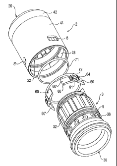
Figs. 1 to 3. The tube coupling has a cylindrical socket 2, at the front face
of which a
connecting portion 20 is provided for a first tube element not depicted here.
Furthermore,
the tube coupling has a sleeve-like plug 3, on the opposite lying front face
of which a
connecting portion 30 is provided for a second tube element not depicted here
either. By
preference, the tube elements are welded to the connecting portions 20, 30. To
establish
a tube connection the plug 3 can be inserted into the socket 2.
Starting in the axial direction from the tip of the plug 3 it has a first
cylindrical portion 34, in
which an annular sealing groove 35 is provided to accommodate a first annular
sealing 71.
In the axial direction the first cylindrical portion 34 is followed by a
splined toothing 32
having a plurality of axial ribs and axial grooves that form the joining
portion for the torque
proof junction. In the part of the axial ribs the plug 3 is designed with a
greater external
diameter than in the first cylindrical portion 34.
In the axial direction the splined toothing 32 is followed by a second
cylindrical portion 36,
in which provision is made for a second annular sealing groove 37 in order to
accommodate
a second annular sealing 72. The external diameter of the plug 3 in the second
cylindrical
portion 36 corresponds approximately to the external diameter of the plug 3 in
the portion
of the ribs of the splined toothing 32. Accordingly, the second annular
sealing 72 is
designed with a greater diameter than the first annular sealing 71.
The second cylindrical portion 36 is followed axially by an annular groove 38
that serves to
secure the axial position of the tube coupling. This annular groove 38 is
followed by a third
cylindrical portion 39, on which a ring-shaped stop 40 is provided. In the
part of the third
cylindrical portion 39 the connecting portion 30 of the second tube element is
provided.
CA 02582609 2009-03-25
-6-
The inner wall of socket 2 is designed corresponding to the outer wall of the
plug 3. Starting
from a plug-in opening 21 for the plug 3 a further annular groove 28 is first
of all provided
on the inner wall of the socket 2, which lies opposite the annular groove 38
of the plug 3
when the plug 3 is inserted completely, i.e. as far as to the stop 40. Along
the annular
groove 28 several approximately rectangular insertion openings 8, 8' are
provided in an
evenly distributed manner in the cylindrical outer wall of the socket 2, which
permit access
to the annular groove 28 from outside. Through these openings locking elements
60 can
be introduced from outside into the annular groove 28 as well as into the
corresponding
annular groove 38, by means of which the plug 3 is secured axially in the
socket 2.
Starting from the plug-in opening 21 the annular groove 28 is followed in the
axial direction
by an internal splined toothing 22 that corresponds to the splined toothing 32
of the plug
3.
For a particularly easy production of the splined toothing 22 the socket is
designed in two
parts having a first sleeve element 41, in which the splined toothing 22 is
provided, and a
second sleeve element 42. The sleeve element 42 that has a smaller internal
diameter
adjoins at its front face onto the splined toothing 22 and is connected to the
first sleeve
element 41 in an integral manner for example.
For an especially good axial securing, locking element pairs are provided in
accordance
with the illustrated embodiment, which each include two individual locking
elements 60, 60'
that are inserted in the opposite sense of rotation into the two annular
grooves 28, 38 on
either side of the insertion openings 8, 8'. To secure the individual locking
elements 60, 60'
in the annular grooves 28, 38 securing bolts 61 are provided that can be
introduced into
corresponding radial bores 9 in the annular groove 38 of the plug 3. Said
radial bores 9 are
distributed with the same distance apart along the circumference of the
annular groove 38.
On the securing bolts 61 retaining sockets 62 consisting of plastic are
arranged, by means
of which the locking elements 60 can be fixed in a force-locking and/or form-
locking
manner. Basically other securing concepts are also conceivable besides the use
of securing
bolts 61 and radial bores 9.
Constructional details of the locking elements 60 can be gathered from Fig. 4
in particular.
The locking elements 60 are designed in a ring-segmented manner and have a
stop 64 in
proximity to their one front face, which projects radially outwards. Through
this stop that
CA 02582609 2009-03-25
-7-
abuts against the wall surrounding the insertion opening 8, 8' the respective
locking element
60 can be prevented from slipping too far into the two annular grooves 28, 38.
On the
opposite front face the locking elements 60 have a bevel 66 that is directed
radially inwards,
i.e. towards the plug 3. The bevel 66 renders it possible that the respective
locking element
60 is positioned during the insertion into the annular groove 38 of the plug
3, whereby the
insertion process is facilitated.
Modifications, variations, and adaptations to the embodiments of the invention
described
above are possible within the scope of the invention, as defined by the claims
appended
hereto.