Note: Descriptions are shown in the official language in which they were submitted.
CA 02582865 2007-04-02
WO 2006/041854 PCT/US2005/035714
CONDUCTING CERAMICS FOR ELECTROCHEMICAL SYSTEMS
RELATED APPLICATIONS
This application claims the benefit of U.S. Provisional Patent Application
Serial No.
60/616,475, filed October 5, 2004, entitled "Conducting Ceramics for Hydrogen
Generation," by Rackey, et al.; and of U.S. Provisional Patent Application
Serial No.
60/662,321, filed March 16, 2005, entitled "Conducting Ceramics for
Electrochemical
Systems," by Rackey, et al. Each of the above applications is incorporated
herein by
reference.
FIELD OF INVENTION
The present invention generally relates to conducting ceramics for
electrochemical
systems and, in particular, to mixed ionically and electrically conducting
ceramics.
BACKGROUND
Currently, there is great interest in using hydrogen as a fuel source.
Hydrogen can
be produced, for example, from carbonaceous fuels. Conventional methods for
the
separation of hydrogen from carbonaceous fuels typically require the steps as
shown in Fig.
1. In summary, these include: (1) a gasification reaction of a carbonaceous
fuel to produce
a syngas (a mixture of water (H20), carbon monoxide (CO) and other compounds);
(2) a
clean-up step, where particulates are removed from the syngas stream; (3) a
water-gas shift
reaction, where the water and carbon monoxide are reacted to produce hydrogen
gas (H2)
and carbon dioxide (C02); and (4) separation of the hydrogen gas.
Syngas can be obtained by reacting a carbonaceous fuel with steam, air, or
pure
oxygen to create a mixture of hydrogen, carbon monoxide, carbon dioxide,
water, and lower
hydrocarbons. Particulates and contaminants produced by this reaction are
removed in
subsequent steps. The syngas stream is then reacted to form hydrogen gas
through the
water-gas shift reaction by passing the syngas stream over a suitable
catalyst. The water-
gas shift reaction is as follows:
H20 + CO _-W~_- H2 + C02.
More advanced "shift" reactors attempt to attain chemical equilibria at a
reduced
temperature, while also performing the entire water-gas shift reaction in a
single reactor. A
subsequent separation step is thus required to remove the COZ that is produced
in this
CA 02582865 2007-04-02
WO 2006/041854 PCT/US2005/035714
-2-
reaction, wliich in this process, is typically done by pressure swing
adsorption techniques.
However, pressure swing adsorption techniques can be energy intensive and
cannot be
performed in a continuous manner.
Other examples of methods of gas separation include diffusion methods that use
a
difference in diffusion coefficients between gas molecules passing through a
material to
effect gas separation. The materials used in these methods typically have
either a
microporosity that allows smaller molecules to diffuse at a higher rate than
larger
molecules, and/or preferentially dissolves certain atoms or molecules, which
creates a
difference in their ability to be transported through the material. However,
fouling of these
materials, as well as cost and energy intensity, are among the reasons that
more advanced
hydrogen gas separation methods are still needed.
SUMMARY OF THE INVENTION
In one aspect, the present invention generally relates to mixed ionically and
electrically conducting materials in a variety of arrangements for a variety
of uses. In one
set of embodiments, the invention relates to conducting ceramics for
electrochemical
systems and, in particular, to mixed ionically and electrically conducting
ceramics. Various
embodiments of the invention involve relatively non-porous, or dense, mixed
conducting
materials, mixed conducting materials with relatively low combined
resistivity, specific
materials for use as mixed ionically and electrically conducting materials
with particular
phase particle or grain size or scale, and structures including mixed
ionically and
electrically conductive materials in multi-layer arrangements including porous
and non-
porous structures, some structures of which can support others in the
arrangement.
The invention also relates, in another aspect, to systems for generating
energy from a
fuel in which a reactor allows fuel (and related impurities, if present) to be
physically
separated from a fuel cell or a related electrochemical energy conversion
device that could
be harmed or fouled by the impurities or other components of the fuel. The
invention also
relates, in certain embodiments, to electrochemical energy conversion systems
able to react
hydrogen to produce electrical energy and water, generating hydrogen from the
water, and
using the hydrogen as fuel in an electrocheinical reaction to generate energy.
In yet another aspect, a system is provided which combines several of the
individual
invention aspects described herein. In this system, a fuel, including or based
solely on
hydrogen, is reacted in a first portion of the reactor (e.g., a fuel cell or
other electrochemical
device) to produce electrical energy. Exhaust, including water, is produced in
the reaction,
CA 02582865 2007-04-02
WO 2006/041854 PCT/US2005/035714
-3-
which is re-converted to hydrogen in a second portion of the reactor in an
electrochemical
reaction driven by consumption of a second, different fuel. The first portion
and second
portion may be contained within the same chamber or vessel, or the first and
second
portions may be in separate vessels that are in fluidic communication, e.g.,
using pipes,
tubing, or the like.
The hydrogen thus generated can be used to generate electricity in the first
portion,
again producing water, which can be reconverted to hydrogen in the second
portion in a
cyclical manner, in some embodiments of the invention. In other embodiments,
the
hydrogen produced in the second portion from water produced by the first
portion can also
be used for other purposes, for example, as fuel for an electrochemical device
not involving
either the first or second portions.
In some embodiments, the second portion involves a mixed ionically and
electrically
conducting material which physically isolates the water produced in the first
portion from a
second fuel provided in the second portion, except for ionic and/or electronic
conduction
across the mixed conducting material. In this way, the second fuel, including
any impurities
if present, can be physically isolated from the first portion, thereby
preventing
contamination of the first portion if such contamination could be detrimental
to the first
portion.
The subject matter of the present invention involves, in some cases,
interrelated
products, alternative solutions to a particular problem, and/or a plurality of
different uses of
one or more systems and/or articles.
In one aspect, the invention is a method. In one set of embodiments, the
method
includes acts of reacting a fuel comprising hydrogen to generate electricity
and water in a
first portion of a reactor, reacting the water to generate hydrogen in a
second portion of the
reactor, and reacting at least a portion of the hydrogen generated in the
second portion of the
reactor to produce electricity. The method, according to another set of
embodiments,
includes acts of reacting a fuel and water across a mixed ionically and
electrically
conducting material, wherein the water is isolated from the fuel except for
ionic and
electronic conduction across the material, to generate hydrogen, and reacting
at least a
portion of the hydrogen to produce electricity.
The method, in one set of embodiments, includes an act of reacting water to
produce
H2 having a purity of at least about 90% (not inclusive of any residual,
unreacted water that
may be present) using electrons provided by a material comprising a first
phase comprising
CA 02582865 2007-04-02
WO 2006/041854 PCT/US2005/035714
-4-
a ceramic ionic conductor and a second phase comprising a ceramic electrical
conductor. In
another set of embodiments, the method includes acts of reacting a
carbonaceous fuel to
produce electrons witliin a material, and reacting the electrons with water to
produce
oxygen ions within the material, the oxygen ions being able to react with the
carbonaceous
fuel. In yet another set of embodiments, the method includes acts of reacting
an oxidizable
species to produce electrons within a material, and reacting the electrons
with a reducible
species that is not in physical contact with the oxidizable species to produce
H2. In some of
these embodiments, the first phase is substantially interconnected throughout
the material
such that the material is ionically conductive, and the second phase is
substantially
interconnected tliroughout the material such that the material is
electronically conductive.
In one set of embodiments, the method includes acts of providing a mixed
ionically
and electrically conducting material having a first side and a second side,
flowing an
oxidizable species across the first side of the material, and flowing a
reducible species
across the second side of the material in a direction that is substantially
countercurrent
relative to the flow of the oxidizable species.
The invention includes a reactor in another aspect. In one set of embodiments,
the
reactor includes a material separating a chamber into a first compartment and
a second
compartment, a carbonaceous fuel source in fluidic communication with an inlet
of the first
compartment, and a source of water in fluidic communication with an inlet of
the second
compartment. In certain embodiments, the material comprises a first phase
comprising a
ceramic ionic conductor and a second phase comprising a ceramic electrical
conductor. In
some cases, the first phase is substantially interconnected throughout the
material such that
the material is ionically conductive, and the second phase is substantially
interconnected
throughout the material such that the material is electronically conductive.
In another set of embodiments, the reactor comprises a mixed ionically and
electrically conducting material having a first side and a second side, a
source of an
oxidizable species directed for flow across the first side of the material,
and a source of a
reducible species directed for flow across the second side of the material in
a direction that
is substantially countercurrent relative to the flow of the oxidizable
species. The reactor, in
yet another set of embodiments, includes a mixed ionically and electrically
conducting
material, having a porosity of less than about 1 open pore/mm2, separating a
chamber into a
first compartment and a second compartment.
CA 02582865 2007-04-02
WO 2006/041854 PCT/US2005/035714
-5-
In still another set of embodiments, the reactor includes a material
separating a
chamber into a first compartment and a second compartment, where the material
comprises
a first phase comprising a ceramic ionic conductor and a second phase
comprising a ceramic
electrical conductor. In some cases, the first phase is substantially
interconnected
throughout the material such that the material is ionically conductive, and
the second phase
is substantially interconnected throughout the material such that the material
is
electronically conductive. In certain embodiments, the ceramic electrical
conductor
includes a ceramic having a formula AlSr,,TiO3, where x is between about 0.1
and about
0.5, and A represents one or more atoms, each independently selected from the
group
consisting of Y, La, Nb, Yb, Gd, Sm, and Pr.
The reactor, in anotlier set of embodiments, comprises a mixed ionically and
electrically conducting material separating a chainber into a first
compartment and a second
compartment. In some embodiments, the material comprises a first phase
comprising a
YSZ ("yttria-stabilized zirconia") material and a second phase comprising a
YST ("yttrium
doped SrTiO3") material. In some cases, the first phase is substantially
interconnected
throughout the material such that the material is ionically conductive, and
the second phase
is substantially interconnected throughout the material such that the material
is
electronically conductive. In still another set of embodiments, the reactor
comprises a
material separating a chamber into a first compartment and a second
compartment, where
the material has a resistivity of less than about 1000 Ohm cm. In some
embodiments, the
material comprises a first phase comprising a ceramic ionic conductor and a
second phase
comprising a ceramic electrical conductor. In still another set of
embodiments, the reactor
comprises a material separating a chamber into a first compartment and a
second
compartment.
Another aspect of the invention is directed to a system. The system includes,
in one
set of embodiments, a gasification chamber; a source of fuel in fluidic
communication with
the gasification chamber; a separation chamber, contained within the
gasification
chamber, fluidically separated from the gasification chamber, at least in
part, by a material
comprising a ceramic, wherein the material is ionically conductive; and a
source of water in
fluidic communication with the second compartment.
Yet another aspect of the invention is directed to an article. The article
comprises, in
one set of embodiments, a substantially non-porous material comprising a first
phase
comprising a ceramic ionic conductor and a second phase comprising a ceramic
electrical
CA 02582865 2007-04-02
WO 2006/041854 PCT/US2005/035714
-6-
conductor, and a porous substrate in physical contact with the material. In
some cases, the
first phase is substantially interconnected throughout the material such that
the material is
ionically conductive, and the second phase is substantially interconnected
throughout the
material such that the material is electronically conductive. In another set
of embodiments,
the article includes a first, porous mixed ionically and electrically
conducting material, and
a non-porous mixed ionically and electrically conducting material in physical
contact with
the first, porous mixed conduction material.
In another aspect, the present invention is directed to a method of making one
or
more of the embodiments described herein, for example, a material comprising a
first phase
comprising a ceramic ionic conductor, and a second phase comprising a ceramic
electrical
conductor. In yet another aspect, the present invention is directed to a
method of using one
or more of the embodiments described herein, for example, a material
comprising a first
phase comprising a ceramic ionic conductor, and a second phase comprising a
ceramic
electrical conductor.
Other advantages and novel features of the present invention will become
apparent
from the following detailed description of various non-limiting embodiments of
the
invention when considered in conjunction with the accompanying figures. In
cases where
the present specification and a document incorporated by reference include
conflicting
and/or inconsistent disclosure, the present specification shall control. If
two or more
documents incorporated by reference include conflicting and/or inconsistent
disclosure with
respect to each other, then the document having the later effective date shall
control.
BRIEF DESCRIPTION OF THE DRAWINGS
Non-limiting embodiments of the present invention will be described by way of
example with reference to the accompanying figures, which are schematic and
are not
intended to be drawn to scale. In the figures, each identical or nearly
identical component
illustrated is typically represented by a single numeral. For purposes of
clarity, not every
component is labeled in every figure, nor is every component of each
embodiment of the
invention shown where illustration is not necessary to allow those of ordinary
skill in the art
to understand the invention. In the figures:
Fig. 1 is schematic representation of a process to produce hydrogen gas from a
carbonaceous fuel source;
Figs. 2A and 2B are schematic representations of various embodiments of the
invention, in which a material of the invention is used in an electrochemical
device;
CA 02582865 2007-04-02
WO 2006/041854 PCT/US2005/035714
-7-
Fig. 3 is an XRD pattern of a YST-8YSZ material that was prepared in
accordance
with one embodiment of the invention, as compared to XRD patterns of isolated
YST and
isolated 8YSZ;
Fig. 4 is a schematic representation of an embodiment of the invention, as
used in a
reactor to oxidize a fuel such as coal to produce hydrogen gas;
Fig. 5 is a schematic representation of another embodiment of the invention,
as used
in a reactor to oxidize a fuel such as coal to produce hydrogen gas; and
Figs. 6A-6D are schematic diagrams of various fuel cells that can be used with
various embodiments of the invention, and the chemical reactions that may
occur during
use.
DETAILED DESCRIPTION
The present invention generally relates, in some aspects, to conducting
materials
such as mixed ionically and electrically conducting materials. A variety of
materials,
material compositions, materials witli advantageous ratios of ionically and
electrically
conducting components, structures including such materials, and the like are
provided in
accordance with the invention.
In one set of embodiments, the invention relates generally to conducting
ceramics
for electrochemical systems and, in particular, to mixed ionically and
electrically
conducting ceramics which can be used, for example, for hydrogen gas
generation from a
gasified hydrocarbon stream. While mixed ceramic conductors are known in the
art, the
present invention provides, in various embodiments, multi-phase systems of
select materials
combined in specific ways to achieve advantageous conductive properties, thin
conductive
materials optionally supported in multi-layer arrangements, and the like.
One aspect of the invention provides a material comprising a first phase
comprising
a ceramic ionic conductor, and a second phase comprising a ceramic electrical
conductor.
An exainple of such a material is a material comprising ZrO2 doped with Sc203
and yttrium-
doped SrTiO3. Another aspect of the invention provides systems and methods of
hydrogen
gas generation from a fuel, such as a carbonaceous fuel, using materials such
as those
described above, for exainple, present within a membrane in a reactor. In some
embodiments, a substantially pure hydrogen stream may be generated through in
situ
electrolysis. In some cases, a material such as those described above may be
used to
facilitate ion and/or electron exchange between a first reaction involving a
fuel such as a
carbonaceous fuel, and a second reaction involving a water-hydrogen conversion
reaction
CA 02582865 2007-04-02
WO 2006/041854 PCT/US2005/035714
-8-
(i.e., where water is reduced to produce hydrogen gas). In other aspects, the
invention
provides systems and methods for producing power from a fuel source, such as a
carbonaceous fuel source.
Various embodiments of the invention use fuels such as carbonaceous fuels for
consumption and/or driving various chemical reactions such as the production
of hydrogen.
Examples of carbonaceous fuels include, but are not limited to, conductive
carbon, graphite,
quasi-graphite, coal, coke, charcoal, fullerene, buckminsterfullerene, carbon
black, activated
carbon, decolorizing carbon, liydrocarbon fuels, an oxygen-containing
hydrocarbon, carbon
monoxide, fats, oils, a wood product, a biomass and combinations thereof.
Hydrocarbon
fuels can be arbitrarily represented using the formula CHy, although in
reality, hydrocarbon
fuels may also contain additional impurities besides carbon and hydrogen, for
example,
sulfur (S), oxygen (0), nitrogen (N), or the like. It should therefore be
understood that, as
used herein, references to "hydrocarbon fuels" or "CXHy" may also include
other impurities
besides pure hydrocarbons, such as sulfur, oxygen, nitrogen, etc. Thus, non-
limiting
examples of hydrocarbon fuels will include saturated and unsaturated
hydrocarbons,
aliphatics, alicyclics, aromatics, and mixtures thereof. Other non-limiting
examples of
hydrocarbon fuels include gasoline, diesel, kerosene, methane, propane,
butane, natural gas,
and mixtures thereof. Examples of oxygen-containing hydrocarbon fuels include
alcohols
which further include C1-CZO alcohols and combinations thereof. Specific
examples include
methanol, ethanol, propanol, butanol and mixtures thereof.
One embodiment of the invention uses, as a fuel, coal, such as bituminous
coal.
Natural coal contains significant amounts of bound hydrogen and water. For
instance, in
bituminous Kentucky coal, the atomic composition is approximately CHo.8i00.08,
which
upon gasification yields a gas mixture with a partial oxygen pressure of about
10"20 atm at
800 C. Additional examples of suitable fuels include, but are not limited to,
fluidized fuels
such as gasified coal, gasified petroleum coke, gasified oils, gasified waxes,
gasified
plastics, gasified waste streams, gasified biologically derived fuels such as
wood,
agricultural waste, sewage sludge, or landfill gas, sewage treatment plant
digester gas,
natural gas, methane, propane, butane, diesel, gasoline, crude oil, bunker (a
by-product from
the petrochemical industry), etc.
As mentioned above, one aspect of the invention is directed to a material that
is able
to conduct both ions and electrons, i.e., the material exhibits "mixed
conduction," since the
material is both ionically and electronically conducting. This material may be
referred to
CA 02582865 2007-04-02
WO 2006/041854 PCT/US2005/035714
-9-
herein as a "mixed ionically and electrically conducting material," a "mixed
conduction
material," or a "MIEC" material. For example, the material may include a
unitary material
that is both ionically and electronically conducting, or the material may
comprise two or
more discrete phases (i.e., discrete regions within the material that have
substantially the
same composition). For example, as is shown in Fig. 2A, a material of the
invention 10
may be used in a reactor, separating a high oxygen partial pressure
environment 12 from a
low oxygen partial pressure environment 14. Material 10, in this example,
includes
ionically conducting phase 11, which is able to conduct oxygen ions, and an
electrically
conducting phase 13, which is able to transport electrons. In such a reactor,
using suitable
reactants, the net result may be oxygen transport across the material from
region 12, having
a high oxygen partial pressure to region 14, having a low oxygen partial
pressure. For
example, in compartment 12, a reduction process may occur (e.g., the
conversion of water
to hydrogen gas), while in compartment 14, an oxidation process may occur (for
example,
the conversion of a fuel to an oxidized fuel, which may be partial or complete
oxidation,
e.g., to water, carbon dioxide, SO2, etc.). Due to the ionization of the
oxygen, an electrical
field may also be created across the material in some embodiments, which may
form at least
a portion of the driving force for transport across the ceramic. It should be
noted that
although oxygen is used in this example, as the ion transported across
material 10, in other
embodiments, other species may be transportable across material 10 instead or
in addition to
oxygen, for example, hydrogen.
Different phases in a mixed conduction material can be identified, for
example, by
identification of the individual portions of material defining the ionically
or electrically
conductive portions. For example, where the mixed conduction material is
ceramic, as
described in more detail below, different phases can be identified by
identification of
individual ceramic grains within the material, in which each phase of the
material generally
comprises grains having different chemical compositions and/or lattice
structures. Discrete
phases within a material can be readily identified by those of ordinary skill
in the art, for
example, using known techniques such as electron microscopy or the like.
In some cases, the materials of the invention, or at least a portion of the
material (for
example, one or more discrete phases of the material), comprises a ceramic.
For instance, in
certain embodiments, the material comprises at least two phases, including a
first phase
comprising a ionic conductor, and a second phase comprising a electrical
conductor, where
the first phase and/or the second phase is a ceramic. Non-limiting examples of
such
CA 02582865 2007-04-02
WO 2006/041854 PCT/US2005/035714
-10-
materials include YST-YSZ compounds, YST-ScSZ compounds, YST-CGO compounds, or
the like, as described in more detail below.
If two or more phases are present, in certain embodiments, they are arranged
with
respect to each other such that the first phase is substantially
interconnected throughout the
bulk of the material such that the material is ionically conductive, and/or
the second phase is
substantially interconnected throughout the material such that the material is
electronically
conductive. As used herein, "substantially interconnected" refers to a pathway
that extends
from a first surface of the material to a second surface that stays within
only one phase of
the material. Thus, for instance, an ionically conductive pathway would allow
an ion, such
as oxygen, to be transported from a first surface of the material to a second
surface of the
material while remaining in only one phase of the material, while an
electronically
conductive pathway would allow electrons to be transported within only one
phase of the
material from a first surface of the material to a second surface of the
material. Preferably,
multiple interconnected pathways exist in the material such that there are
multiple ionically
conductive pathways and multiple electrically conductive pathways from the
first surface to
the second surface of the material sufficient to achieve, in some embodiments,
conductive
and/or resistive properties as described below. Those of ordinary skill in the
art can readily
formulate materials using the disclosure herein to achieve these results. As
examples, the
material may comprise a first ionically conductive phase and a second
electronically
conductive phase that intertwines (e.g., 3-dimensionally) with the first
phase, or the material
may comprise a third phase, through which a first ionically conductive phase
and a second
electronically conductive phase pass.
If two phases are present in the material, the phases may be present in any
ratio, for
example, the ionically conductive phase may be present in the material at a
percentage of
between about 5% and 98% by weight, between about 10% and about 95% by weight,
between about 30% and about 92% by weight, between about 40% and about 90% by
weight, etc., with the balance being the electrically conductive phase. In
some
embodiments, for example in the case of ceramic mixed ionically and
electrically
conducting materials, one phase (e.g., the ionically conductive phase in the
case of most
ceramic materials) is significantly more resistive than the electrically
conductive phase.
The present invention recognizes this characteristic and, accordingly,
provides the ability to
tailor the ratios of the two materials relative to each other (as well as
other properties such
as density) to impart balanced conductivity while maintaining good
conductivity of each
CA 02582865 2007-04-02
WO 2006/041854 PCT/US2005/035714
-11-
phase throughout the material. That is, in such a situation more ionically
conductive
material can be provided relative to the electrically conductive material, to
offset the
increased resistivity of the ionically conductive phase, without altering the
ratio of ionically
to electrically conductive material so much so that the electrically
conductive material is not
present in sufficient quantity to provide sufficient electrically conductive
interconnected
pathways throughout the material to provide sufficient electric conductivity.
For example,
the ionically conductive phase may be present in a percentage as described
above, or
between about 50% to about 90% by weight, or 60% to about 88% by weight, with
the
balance being the electrically conductive phase. In other embodiments, these
ratios exist
between the ionically and electrically conductive phases relative to each
other, but other
components in the material can be present, reducing the overall a.inount of
both the
electrically and ionically conductive materials below their percentage
presence relative to
each other.
As used herein, a"ionically conducting material" is a material in which one or
more
types of ions are able to be transported through, for example, oxygen ions or
hydrogen ions.
In one set of embodiments, the ionic conductor is, or comprises, a ceramic
ionic conductor.
The ceramic ionic conductor may comprise, in some cases, one or more of a La-
ferrite
material, a ceria, and a zirconia, each of which may be doped or undoped, as
described in
more detail below. A non-limiting example of a ceramic ionic conductor is La-
ferrite
material, e.g., a material comprising La, Sr, Cr, Fe, and O(for example, an
"LSCrF"
material such as Lao,2Sr0,8Cro.2Feo,803).
In some cases, the ceramic ionic conductor has a perovskite structure, or a
cubic
structure. At relatively low oxygen partial pressures (for example, at a pO2
below about 10"
1s atm), the ceramic ionic conductor may have an ionic conductivity of about
0.2 S/cm to
about 0.8 S/cm at a temperature of between about 800 C and about 1000 C. In
other cases,
the ionic conductivity may be at least about 0.2 S/cm, at least about 0.3
S/cm, at least about
0.4 S/cm, at least about 0.5 S/cm, at least about 0.6 S/cm, at least about 0.7
S/cm, at least
about 0.8 S/cm, at least about 0.9 S/cm, or at least about 1.0 S/cm or more at
such
temperatures.
In one embodiment, the ionic conductor comprises a cerate (i.e., a cerium
oxide), for
example, ceria or CeO2. Examples of ceria-containing materials include, but
are not limited
to, a Ce02-based perovskite, such as Ce0,9Gdo,102 or Cel_XGd,,O2, where x is
no more than
about 0.5, or lanthanum-doped ceria, such as (Ce0)1_n(La05)n where n is from
about 0.01 to
CA 02582865 2007-04-02
WO 2006/041854 PCT/US2005/035714
-12-
about 0.2. In some cases, the ceria may be doped with gadolinium. For example,
during
production, a gadolinium oxide and a cerium oxide may be mixed together to
produce a
"CGO" (gadolinium-doped cerium oxide). The CGO material may have a perovskite
structure. The CGO material may include about 10% to about 20% gadolinium, or
about
12% to about 18% gadolinium. In certain cases the CGO material may have a
conductivity
of between about 0.06 S/cm and about 0.24 S/cm at a temperature of between
about 700 C
and about 900 C, at relatively low oxygen partial pressures (e.g., below
about 10-15 atm),
and/or in an oxidizing atmosphere. Below a partial pressure of about 10-1s
atm, the CGO
material may exhibit higher ionic conductivities. For instance at a partial
pressure of 10-18
atm and a temperature of 900 C, the CGO material may have an ionic
conductivity of over
about 0.4 S/cm and an electronic conductivity of about 1.6 S/cm. CGO may also
have the
added benefit of acting as a catalyst for reduction. Such a reduction may
effectively
increase the interfacial area of the material.
In yet another embodiment of the invention, the ionic conductor comprises a
zirconia (i.e., a zirconium oxide material). Examples of zirconia materials
include, but are
not limited to, (Zr02)(Zr02)(Hf02)o.o2(Y2O3)o.os, (Zr02)(Y203)o.os,
(Zr02)(Hf02)o.o2(Z'203)o.os, (Zr02)(Hf02)o.02(1'203)o.os,
(Zr02)(Hf02)o.o2(Y203)o.os(Ti02)o.io,
(Zr02)(Hf02)o.o2(Y2O3)o.oa(A1203)o.io, (ZrOa)(Y203)o.os(Fe203)o.os,
(Zr02)(Y203)o.os(CoO)o.os, (Zr02)(Y203)o.os(ZnO)o.os,
(Zr02)(Y203)o.os(NiO)o.os,
(Zr02)(Y203)o.os(CuO)o.os, (Zr02)(Y203)o.os(MnO)o.os and ZrO2CaO. In some
embodiments,
the zirconia may be stabilized in a cubic structure using one or more dopants,
for example,
metals such as nickel, or transition metals such as Y or Sc, which can be
added in a quantity
sufficient to give the doped zirconia a cubic structure. For instance, during
production of
the zirconia, yttria (Y203) and/or scandia (Sc203) may be added as a dopant
material to
produce a yttria-stabilized zirconia material ("YSZ"), a scandia-stabilized
zirconia material
("ScSZ"), or a zirconia stabilized with both yttria and scandia. As used
herein, a material
that "stablizes" zirconia is a material that has been added (doped) to the
zirconia in a
quantity sufficient to cause the zirconia to form a cubic structure. The
yttria and/or scandia
may be added in any suitable concentration, for example, at mole ratios of
about 2 mol%,
about 4 mol%, about 6 mol%, about 8 mol%, about 10 mol%, etc. As non-limiting
examples, an "8YSZ" material (i.e., a YSZ material doped with 8 mol% yttria)
can be
prepared, which may have an ionic conductivity of between about 0.02 S/cm to
about 0.1
S/cm at a temperature of between about 800 C and about 1000 C; or a"10ScSZ"
material
CA 02582865 2007-04-02
WO 2006/041854 PCT/US2005/035714
- 13-
(i.e., a ScSZ doped with 10 mol% scandia) can be prepared, which may have an
ionic
conductivity of between about 0.1 S/cm and about 0.3 S/cm at a temperature of
between
about 800 C and about 1000 C. YSZ that is not compounded with an ionically-
conductive
material may also be useful in certain embodiments.
In still other embodiments, the ionic conductor may comprise a material having
a
formula (Zr02)(HfO2)a(TiO2)b(A1203)c(Y2O3)d(MXOy)e where a is from 0 to about
0.2, b is
from 0 to about 0.5 c is from 0 to about 0.5, d is from 0 to about 0.5, x is
greater than 0 and
less than or equal to 2, y is greater than 0 and less than or equal to 3, e is
from 0 to about
0.5, and M is selected from the group consisting of calcium, magnesium,
manganese, iron,
cobalt, nickel, copper, and zinc. Non-limiting examples include a LaGaO3-based
perovskite
oxide, such as Lal_xAXGaI_yByO3 where A can be Sr or Ca, B can be Mg, Fe, Co
and x is
from about 0.1 to about 0.5 and y is from about 0.1 to about 0.5 (e.g.
La0,9Sr0.1Ga
o.aMgo.203); a PrGaO3-based perovskite oxide electrolyte, such as
Pro.93Sro.o7Gao.s5Mgo.i503
or Pro.93Cao.o7Gao.ssMgo.is03; and a Ba2In205-based perovskite oxide
electrolyte, such as
Ba2(Inl,GaX)2O5 or (Bal_XLaX)In2O5, where is x is from about 0.2 to about 0.5.
As used herein, an "electronic conducting material" is a material through
which
electrons can be readily transported. The electronic conductor may be, for
example, a
conducting material or a semiconducting material. The electronic conductor, in
one set of
embodiments, may be, or coinprise, a ceramic electronic conductor. For
instance, the
ceramic electronic conductor may comprise one or more of a LST material, a YST
material,
a YLST material, and an LCC material. As used herein, "LCC" refers to any
lanthanum-
calcium-chromium oxide, i.e., the LCC material comprises La, Ca, Cr, and 0,
for example,
Lao.sCao,2CrO3. Lao.8Cao,2CrO3 can have, in some embodiments, an electronic
conductivity
of ranging between about 40 S/cm (e.g., in reducing atmospheres) to about 80
S/cm (e.g., in
oxidizing atmospheres). In some cases, pressureless sintering to full density
of the LCC at
1400 C may be used.
In one embodiment, the ceramic electronic conductor comprises a YST (Y-Sr-Ti)
material, i.e., a ceramic material comprising Y, Sr, Ti, and 0, for example,
Sro.asYo.osTiO3=
In some cases, the YST material may have a formula Yl_,tLaTiO3, where x may be
between
about 0.1 and about 0.5, or between about 0.2 and about 0.4 in some cases. YST
materials
may also have reduced electrode polarization in some cases. In some
embodiments, the
YST material may be prepared by doping SrTiO3 with yttrium. Such a YST
material may
have a relatively high electronic conductivity at an elevated temperature, for
example, an
CA 02582865 2007-04-02
WO 2006/041854 PCT/US2005/035714
-14-
electronic conductivity of about 50 S/cm to about 80 S/cm at a temperature of
800 C and an
oxygen partial of between about 10-14 a.nd about 10-19 atm. As a particular
non-limiting
example, a YST material was prepared and sintered at a temperature of 1400 C.
X-ray
diffraction ("XRD") analysis of this material showed no evidence of reactions
(Fig. 3), and
analysis via SEM showed excellent densification. In Fig. 3, the upper graph
shows an XRD
pattern for a 50/50 wt% YST-8YSZ material that was sintered at 1400 C for 5
hours. The
two smaller graphs (below) show the XRD patterns of the two individual
components based
on lcnown standards of isolated YST and isolated YSZ. Each line in the top
graph is found
back on either of the two smaller graphs, and therefore it can be concluded
that there are no
new compounds formed in this example that could be detected using XRD.
In another embodiment, the ceramic electronic conductor may comprise a
material
comprising a LST (La-Sr-Ti) material, i.e., a ceramic material comprising La,
Sr, Ti, and O.
Such materials can be produced, for instance, by doping SrTiO3 with a
lanthanum oxide.
The LST material may have a formula Srl_xLaXTiO3 in some embodiments, where x
may be
between about 0.1 and about 0.5, or between about 0.2 and about 0.4 in some
cases. For
example, the lanthanum oxide may be added at a dopant at concentrations of
between about
mol% La and about 40 mol 1 .
In yet another embodiment, the ceramic electronic conductor may be both an LST
and a YST material (a "YLST" material), i.e., the ceramic material comprises
Y, La, Sr, Ti,
20 and O. The YLST material may have a formula (YZSrI_Z)1_XLaXTi03, where x
may be
between about 0.1 and about 0.5, or between about 0.2 and about 0.4 in some
cases, and z
may be any number between 0 and 1, for example, 0.25, 0.5, 0.75, etc. In still
other
embodiments, the material may comprise a strontium titanate doped with one or
more of Y,
La, Nb, Yb, Gd, Sm, and Pr. For example, in one embodiment, the material has a
formula
Al_XSrXTi03, where A represents one or more atoms, each independently selected
from the
group consisting of Y, La, Nb, Yb, Gd, Sm, or Pr, and x may be between about
0.1 and
about 0.5, or between about 0.2 and about 0.4 in some cases. For instance, Al,
in this
structure may represent A'a, (i.e., Ali_xLaXTi03), A'a,A2a2 (i.e., A'a,A2a2
LaXTiO3),
A'a,A2a2A3a, (i.e., A'a,A2aZA3a, LaxTiO3), ..., etc., where each of Al, AZ,
A3, ..., etc. is
independently selected from the group consisting of Y, La, Nb, Yb, Gd, Sm, or
Pr, and each
of al, a2, a3, ..., etc. sums to 1-x.
CA 02582865 2007-04-02
WO 2006/041854 PCT/US2005/035714
- 15-
As noted above, the invention provides materials in which both the
electrically and
ionically conducting phases perform well, and this generally means provision
of a good
network of interconnected, continuous ionically and electrically conductive
pathways,
respectively, throughout the material. Ratios of phases relative to each other
(where two-
phase materials are provided) are described above in this regard. Another
factor which
those of ordinary skill in the art can adjust based on the present disclosure,
to achieve good
conductivity, is the density of the material, and/or the porosity. A more
dense material will,
in general, include more contact between individual portions of material
phases (e.g., grains
of ceramic), maximizing the presence of continuous conductive pathways of
each. For
example, in certain cases, the mixed ionically and electrically conducting
material may have
a density of at least about 80%. For example, the density of the material may
be at least
about 85%, at least about 90%, or at least about 95%, as measured on a
volumetric basis.
Those of ordinary skill in the art will know of suitable techniques for
measuring the relative
density of a material on a volumetric basis.
In some embodiments, the mixed ionically and electrically conducting material
is
substantially non-porous, i.e., the porosity of the material is less than
about 1 open
pore/mm2, and this can improve ionic and/or electrical conductivity. For
example, the
material may have a porosity of less than about 1 open pore/mm2 less than
about 1 open
pore/cm2 or the like. "Open pores" can be measured in a material by creating a
pressure
differential from one side of the material to the other side that is at least
about 5 psi (34.5
kPa), coating the lower-pressure surface with a thin film of a liquid such as
alcohol, and
determining the number of bubbles that are created due to the pressure
differential, where
the presence of a stream of bubbles indicates the presence of an open pore.
Another
example method of determining porosity is a helium leak test, where a leak
rate in the order
of at most 0.01 cm3/min of helium per cm2 of cell area and per psi of pressure
would be
required (1 psi is about 6.9 kilopascals (kPa)).
Combinations of density, non-porosity, ratio of ionically to electrically
conductive
phase, and/or other adjustments can be made based on this disclosure to tailor
combined
conductivity of material, i.e., combined (ionic and electrical) resistivity.
For example, the
material may have a resistivity of less than about 1000 Ohm cm (S2 cm), less
than about 750
Ohm cm, less than about 500 Ohm cm, less than about 250 Ohm cm, less than
about 200
Ohm cm, less than about 150 Ohm cm, less than about 100 Ohm cm, etc.
CA 02582865 2007-04-02
WO 2006/041854 PCT/US2005/035714
-16-
The material may also be substantially gas impermeable in certain cases, i.e.,
the
material can be used to maintain separation of a first gas in a first
coinpartment of a
chamber on one side of the material and a second gas in a second compartment
on another
side of the material (for example, with compartments being on each side of the
material, as
illustrated schematically in Fig. 2A), both gases being at ambient pressure
(about 1 atm).
For example, the ionically and electrically conducting material may be
sufficiently gas
impermeable that, if two gases are placed on either side of a mixed ionically
and electrically
conducting material, less than about 5% of the gases, less than about 3%, or
less than about
1% of the gases on either side of the material are able to mix after a period
of at least a day.
In some cases, no mixing of the gases can be detected after a day.
In other embodiments, however, the material is porous, and allows at least
some gas
to be transported therethrough. In some cases, the material may be selectively
permeable,
that is, permeable to some but not other gases. For example, the material may
be permeable
to hydrogen gas, but impermeable to other gases. In one embodiment, the
material is
sufficiently porous that pressure differences between a first side and a
second side of the
material may be used to direct the transport of gas across the material, e.g.,
from a higher
pressure to a lower pressure. In other embodiments, the material is gas
impermeable at
ambient pressure, but at higher pressures, the material may be permeable or
selectively
permeable to gases.
In one set of embodiments, the invention provides structures using mixed
ionically
and electrically conducting materials. For example, the mixed ionically and
electrically
conducting material can be positioned in contact with a substrate, such as a
porous
substrate. The porous substrate may have a porosity that is at least
sufficient to allow access
to the material by gases such as oxygen, hydrogen, and/or water vapor, while
providing at
least some mechanical stability of the material, for instance, if the mixed
ionically and
electrically conducting material is present as a thin layer, for example,
having a thickness of
less than about 50 micrometers, for instance, between about 10 and about 20
micrometers or
between about 10 and about 40 micrometers. The material, at these or other
thicknesses,
also may have a particularly high overall aspect ratio, i.e., its thickness
may be quite small
relative to another dimension perpendicular to the thickness, or to two other
dimensions
each perpendicular to the thickness. Where aspect ratio is defined as the
ratio of at least one
dimension perpendicular to thickness, to the thickness itself, mixed
conductive material of
the invention having an aspect ratio of at least about 5:1, 10:1, 20:1, 50:1,
or 100:1 may be
CA 02582865 2007-04-02
WO 2006/041854 PCT/US2005/035714
-17-
provided, optionally with an adjacent, supporting substrate that can be porous
(e.g. in a
layered arrangement). The substrate may have any shape. For example, in one
embodiment, the material is deposited on the outside of a substrate that is a
porous tube. In
another embodiment, the material is deposited on the surface of a planar
porous substrate.
The porous substrate may be any suitable porous material, for example, a
ceramic, a
polymer, or a metal.
Accordingly, in one set of embodiments, a mixed ionically and electrically
conducting material, which can be ceramic, is provided having a first side and
a second
opposing side, one or both sides addressed by a porous, supporting layer. One
or more of
the porous, supporting layers can, itself, be a mixed ionically and
electrically conducting
material, or simply ionically conductive or or electrically conductive, and
each can, in some
cases, be supported by an auxiliary, porous, inert layer. In one such
arrangement, a multi-
layer structure exists, comprising a first, porous layer, and a second,
ceramic, dense mixed
conduction material. In another arrangement, the multi-layer structure
comprises first,
porous layer, a second, ceramic, dense mixed conduction material, and a third,
porous layer.
In yet another arrangement, the multi-layer structure coinprises a first,
porous layer, a
second, porous mixed conduction material, a third, ceramic, dense mixed
conduction
material, and a fourth porous mixed conduction material. In another
arrangement, a multi-
layer structure exists, comprising a first, porous layer, a second, porous
mixed conduction
material, a third, ceramic, dense mixed conduction material, a fourtlz, porous
mixed
conduction material, and a fifth, porous layer.
In some cases, e.g., if the surface of the deposited material is too "smooth,"
an
additional layer of powder may be added to the surface of the mixed conducting
material
that has been deposited on the porous substrate. For example, the powder may
be a powder
of the mixed conducting material, which can be deposited on a surface of the
mixed
conducting material, or another type of powder. In one embodiment, the
additional layer of
powder is deposited using vacuum intrusion, which may also assist in reducing
polarization
of the powder in some cases.
In another aspect of the invention, hydrogen, for example substantially pure
hydrogen gas, is produced using a reactor containing a mixed ionically and
electrically
conducting material, such as those described herein. For example, with
reference to Fig.
2B, a mixed ionically and electrically conducting material 10 may be used to
separate first
compartment 21 and second compartment 22. In compartment 21, a fuel is
oxidized, for
CA 02582865 2007-04-02
WO 2006/041854 PCT/US2005/035714
- 18-
example, to produce an oxidized fuel, which may be partial or complete
oxidation, e.g., to
water, carbon dioxide, SO2, etc., while in compartment 22, a reduction
reaction occurs, for
example, water is reduced to produce hydrogen gas, i.e., in situ electrolysis.
Oxygen that is produced from the reduction of water to hydrogen gas (or other
reduction reaction) is transported across material 10 from compartment 22 to
compartment
21, where it can react with the fuel, while electrons that are generated from
the oxidation of
the fuel return across material 10 to participate in the reduction of water to
hydrogen gas.
The hydrogen gas produced in this reaction may be separated and isolated,
and/or routed to
devices that can consume hydrogen, for example, fuel cells as discussed in
detail below.
Thus, in certain embodiments, a reactor of the invention may oxidize a fuel
and
simultaneously produce hydrogen gas within the same reactor.
In some embodiments, the oxygen used to oxidize the fuel comes only from the
mixed conducting material at steady state, although additional oxygen may be
added for
start-up, thermal balance requirements. In other embodiments, however,
additional oxygen
may be supplied even during steady state, for example, if more complete
oxidation of the
fuel is desired, if higher reaction temperatures are needed, etc.
The hydrogen gas produced by the reactor may exit the reactor in a first
stream,
while waste gases produced from the oxidation of the fuel may exit the reactor
in a second
stream, and/or be used in other operations within the reactor. The hydrogen
gas that is
produced by the reactor is thus substantially pure and free of contaminants
(gaseous,
particulate, etc., e.g., which may be present within the fuel), as the
hydrogen gas is
produced in a physically separate compartment than the compartment where the
fuel has
been oxidized. Such a physically separate arrangement may be advantageous, for
example,
in embodiments where impurities or other coinponents of the fuel could harm or
foul the
reduction of water to hydrogen gas. Thus, a substantially pure hydrogen stream
can be
produced in some embodiments. For example, the substantially pure hydrogen
stream may
be at least about 90%, at least about 95%, at least about 97%, at least about
98%, or at least
about 99% pure on a volumetric basis. In other embodiments, however, some
water may be
present within the hydrogen stream exiting the reactor (i.e., a "wet hydrogen"
stream). Of
course, in such cases, such a wet hydrogen stream may optionally be
subsequently separated
into water and hydrogen gas, before and/or after leaving the reactor, for
example, using a
condensation operation.
CA 02582865 2007-04-02
WO 2006/041854 PCT/US2005/035714
-19-
In some cases, the waste gases may be recycled within the reactor, for
example, to
facilitate gasification of a fuel, for instance, a carbonaceous fuel such as
coal. Examples of
recycling processes are illustrated in Figs. 4 and 5. In one embodiment,
partially oxidized
fuels exiting the reactor may be recycled to effect further oxidation. In
another
embodiment, waste gases such as water and carbon dioxide are used as reactants
for the
gasification of coal according to the following endothermic reactions:
C + CO2 - - 2C0 AH =+170 kJ/mol at 800 C
C+ H2O - CO + H2 AH =+136 kJ/mol at 800 C.
In some embodiments of the invention, the same pressure is used on both sides
of
the mixed conducting material. However, in other embodiments of the invention,
the
pressures on the material are not necessarily the same. For example, in some
cases, the
pressure within the water-hydrogen reaction compartment may be greater, while
in other
embodiments, the reaction in this compartment may be less than the pressure in
the fuel
oxidation compartment. In certain cases, one or both pressures on the material
may be
ambient pressure. Even if the material is porous and/or at least partially
selectively
permeable, substantially pure hydrogen gas can still be produced, for example,
if the
pressure in the water-liydrogen reaction compartment is greater than the
pressure in the fuel
oxidation compartment such that gases from the fuel oxidation compartment are
not able to
cross the material due to the pressure difference.
The reactor, as described above, does not necessarily require a water-gas
shift
reaction that produces hydrogen gas directly from syngas, and therefore raw
gasified
carbonaceous fuel streams can be oxidized to produce hydrogen gas, in contrast
to prior art
systems where a fuel or syngas stream needs to be additionally processed to be
free of
contaminants such as H2S, which can poison catalysts in those prior art
systems. In certain
embodiments, the reactor can be placed within a gasifier compartment itself
(i.e., the
compartment in which a carbonaceous fuel is reacted to produce a gasified
hydrocarbon,
such as syngas), for instance, as is illustrated in the example shown in Fig.
5, and discussed
in detail below
It should be noted that the system, as described above, is by way of example
only
and is not intended to be limiting, and other reactions are also contemplated
within the
scope of the present invention. For example, any reduction reaction may be
used within the
CA 02582865 2007-04-02
WO 2006/041854 PCT/US2005/035714
-20-
reduction compartment, besides the reduction of water to hydrogen gas, that is
able to
produce ions that can be transported across the mixed conducting material, for
example, a
reduction reaction that produces oxygen ions, hydrogen ions, or the like.
Similarly, other
fuels can be used besides carbonaceous fuels within the oxidation chamber,
which fuels
may produce electrons when oxidized (partially or completely) that can be
transported
across the mixed conducting material.
Those skilled in the art will recognize that the above-described system will
work for
any process in which there is an oxidizable species on one side of a mixed
conducting
material, as disclosed herein, and a reducible species on the other side.
Thus, as another
example, CO2 can be reduced to CO on one side of the mixed conducting
material, while
methane (for instance, from natural gas) may be oxidized on the other side of
the mixed
conducting material, e.g., as follows:
4CO2 + 8e" 4 4C0 + 402- cathode
CH4 + 402" __> CO2 + 2H20 + 8e anode
In one set of embodiments, the flow within the reactor of the oxidizable
species
(e.g., a fuel) and the reducible species (e.g., water) may be co-current,
e.g., the flow of both
species across the mixed conducting material occurs in substantially the same
direction. In
other embodiments, however, the flow may be counter-current (e.g., the flow of
both
species is in substantially opposite directions) or cross-current (e.g., the
flow of both species
is not co-current nor counter-current flow). Counter-current flow may give
certain
advantages, for example, greater efficiency, or better purity of the resultant
streasns after
reaction, relative to co-current or cross-current flow. For instance, in
counter-current flow,
an oxidiziable species entering the reactor may be substantially oxidized upon
leaving the
reactor (e.g., by being in electronic/ionic communication with a substantially
unreduced
reducible species near the outlet for the oxidizable species), while a
reducible species
entering the reactor may be substantially reduced upon leaving the reactor
(e.g., by being in
electronic/ionic communication with a substantially unoxidized oxidizable
species near the
outlet of the reducible species).
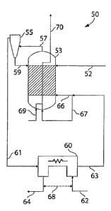
One non-limiting example of such a reactor is shown in Fig. 4, in which
reactor 50
comprises several different units or vessels therein. In the arrangement
illustrated
schematically in this figure, water and a fuel source, such as coal, are fed
to reactor 50, and
CA 02582865 2007-04-02
WO 2006/041854 PCT/US2005/035714
-21-
are reacted to produce hydrogen gas and waste gases, such as CO2. Coal is fed
in coal feed
52 to gasifier 53. Of course, in other embodiments, other fuels may be used
instead or in
addition to coal, for example, carbonaceous fuels such as those previously
described.
Within the gasifier, the coal (or other fuel) is broken down and fluidized to
produce a
hydrocarbon stream, e.g., a stream comprising a mixture of water, CO, COZ,
lower
hydrocarbons (e.g., organic molecules containing fewer numbers of carbon than
initially fed
to the gasifier, for example), unreacted hydrocarbons, and/or other compounds,
such as
impurities, inorganic entities, or the like. In some embodiments, the
gasification is
conducted in such a manner that a syngas is formed.
Typically, the hydrocarbon stream will include impurities, unreacted fuel, and
the
like. In some cases, these may be present as particles within the stream. In
some cases,
these may be removed from the hydrocarbon stream using separation techniques
known to
those of ordinary skill in the art, for example, using filters, cyclones,
centrifugal separators,
impingement separators, or the like. For example, as is shown in Fig. 4, a
cyclone 55 is
used to separate a hydrocarbon stream 57 produced in gasified 53 from various
impurities,
unreacted fuel, etc. Optionally, the impurities, unreacted fuel, etc. may be
fed back to
gasifier 53 in streain 59.
The hydrocarbon stream, upon leaving cyclone 55, flows through stream 61 to
reaction chamber 60. Also entering reaction chamber 60 is stream 62. Stream 62
contains
water, for example, which may be present as steam. Reaction chamber 60
contains a mixed
conducting material which separates the reaction chamber into two (or more
compartments),
at least one of which is fed by stream 61 and at least one of which is
separately fed by
stream 62. Within reaction chamber 60, the hydrocarbon stream is oxidized, for
example,
completely to produce C02, while the water is reduced to H2, e.g., using the
reaction
schematic illustrated in Fig. 2B. H2 (which may or may not include water)
leaves the
reactor through stream 64 (and can be collected and/or purified), while the
oxidized fuel
leaves the reactor through stream 63. In some cases, heat may be exchanged
between
streams 62 and 64, e.g., using a heat exchanger as is indicated by heat flow
68, wliich may
increase the overall efficiency.
In some embodiments, depending on the efficiency of reaction chamber 60, a
scrubber and/or an absorbent bed (not shown) may be added to stream 63. Stream
63, upon
exiting reaction chamber 60, is fed back to gasifier 53. This creates a
recycling operation
that may increase the overall efficiency of the system. In the example shown
in Fig. 4,
CA 02582865 2007-04-02
WO 2006/041854 PCT/US2005/035714
-22-
stream 63 divides into streams 66 and 67. Stream 66 is fed to the coal bed,
being the
gasification agent for the next cycle, and stream 67 is fed to a burner where
the remaining
CO burns with oxygen or air, introduced through stream 69. This is indicated
by the dotted
lines within the gasifier 53, which represents, for instance, a tube bundle in
the reactor,
through which combustion products may flow. These give off heat to the
gasifier, which
may assist the endothermic gasification process. The gases then exit the
gasifier 53 in
stream 70, which may include waste gases such as C02, H20, and the like. In
some cases,
the CO2 may be further processed and/or sequestered.
Another example of an embodiment of the invention is shown in Fig. 5. In this
figure, although the arrangement is similar to that shown in Fig. 4, here, the
reaction
chamber 60 is now positioned internally of gasifier 53. As before, water
(steain) is fed to
reaction chamber 60, which is isolated from gasifier 53 through the use of a
mixed
conducting material. However, instead of a separate hydrocarbon stream as was
shown in
Fig.4, in the embodiment shown in Fig.5, the fuel within gasifier 53 is
directly exposed to
the mixed conducting material. Such an arrangement may yield additional
efficiency, as the
heat lost from the reaction chamber is utilized witliin gasifier 53.
The hydrogen gas produced using techniques such as those described above may
be
separated from the reactor, e.g., for use in reactions or power generation, or
in some aspects
of the invention, the hydrogen gas may be oxidized to produce electrical
power, for
example, in a fuel cell. In some cases, the process of power generation may
occur
simultaneously with hydrogen gas production. Any suitable system that can
react hydrogen
gas to produce water and power may be used, for example, fuel cells. Non-
limiting
examples of fuel cells include solid oxide fuel cells, molten carbonate fuel
cells, phosphoric
acid fuel cells, polymer electrolyte fuel cells (e.g., using proton exchange
membranes),
alkaline fuel cells, or the like. Thus, in one embodiment, hydrogen is
provided in a reactor
(e.g., supplied externally as a fuel, and/or produced by the reactor), which
is reacted in a
first portion of a reactor to produce water, and then re-converted to hydrogen
in a second
portion of the reactor. The hydrogen may be re-cycled back to the first
portion of the
reactor, e.g., as is shown in Figs. 6A-6D, and/or the hydrogen may be
separated as described
above, or even used as a fuel for an electrochemical device not involving
either the first or
second portions, as a reactant for a chemical process, or the like. The first
portion and
second portion may be contained within the same chamber or vessel, or the
first and second
portions may be in separate vessels that are in fluidic communication, e.g.,
using pipes,
CA 02582865 2007-04-02
WO 2006/041854 PCT/US2005/035714
- 23 -
tubing, or the like, for example, a first vessel may contain a mixed
conduction material (e.g.,
as described herein) and a second vessel may contain a fuel cell, a vessel may
contain
therein both a mixed conduction material and a fuel cell (e.g., such that
hydrogen and/or
water within the vessel is in fluid communication with both the mixed
conduction material
and the fuel cell), or the like. Those of ordinary skill in the art will be
able to engineer and
build suitable systems using no more than routine skill with the disclosures
described
herein, for example, by adding, as appropriate, reaction vessels, piping,
tubing, heat
exchangers, gas collection systems, and the like.
Figs. 6A-6C illustrates several general reaction schemes, using a mixed
conduction
material of the invention 30, together with a fuel cell. In these figures,
both electrons (e")
and oxygen can be transported across mixed conduction material 30, which
separates an
oxidation compartment 31 from a reduction compartment 32. On one side of
material 30, a
fuel, such as a carbonaceous fuel, optionally comprising sulfur or other
impurities
(represented as CXHy + SZ) can be completely oxidized to produce H20, C02,
SO2, etc. In
other embodiments, however, the fuel may be only partially oxidized. The
oxidation
reaction also produces electrons, which are transported across the mixed
conduction
material 30. The electrons are used in a reduction reaction, e.g., reacted
with water (H20) to
produce hydrogen gas (H2) and oxygen ions. The ions can be transported across
mixed
conduction material 30.
The hydrogen gas may be used to regenerate water in the fuel cell, optionally
producing electric current in the process, which may be harnessed. The fuel
cell may be
separate from the reactor where hydrogen is produced from water, for example,
contained
within a compartment or a vessel that is physically separate from, but is in
fluidic
communication with, the compartment in which hydrogen is produced from water;
or in
some cases, the fuel cell may be an integral part of the reactor, i.e., in a
coinpartment of the
reactor, a mixture of hydrogen and water (which may be present as steam) is
simultaneously
exposed to a reaction in which hydrogen is produced from water (e.g., using a
mixed
ionically and electrically conducting material, as previously described), and
a reaction in
which water is produced from hydrogen (e.g., in a fuel cell). The fuel cell
may react H2 to
produce water (H20) by reaction with hydroxide ions (OH"), oxygen ions (02-),
carbonate
ions (C032"), etc., which in the process, may release electrons that can be
harnessed as
power 3 5.
CA 02582865 2007-04-02
WO 2006/041854 PCT/US2005/035714
-24-
It should be noted that the net result of such a reaction system, as is shown
in Figs.
6A-6D, is that oxygen enters the fuel cell, and, through a series of
reactions, reacts with and
oxidizes the fuel. Thus, there is a net transport of oxygen through this
reaction system, as is
shown by arrow 37.
In Fig. 6A, as an example, an alkaline fuel cell is demonstrated, where Off is
transported through the fuel cell to reduce hydrogen gas to water (H2 + 20H- --
> 2H20 +
2e ), in the process generating electrons which are harnessed. The Off may
come from a
source such as pure oxygen source, or from air (as is shown in Fig. 6A) or
another source
comprising oxygen, for example, produced using water in the reaction (02 +
2H20 + 4e -->
40H"). In some cases, the alkaline fuel cell uses a matrix 34 saturated with
an aqueous
alkaline solution, such as potassium hydroxide (KOH), in which the Off is
transported.
In Fig. 6B, a fuel cell using a proton exchange membrane is demonstrated. In
this
fuel cell, protons can transport through the proton exchange membrane,
although electrons
cannot. Thus, while protons (H+) passes through the membrane, the electrons
nlust pass
through an external circuit, where they can be harnessed for power 35. In this
system, some
of the hydrogen gas within compartinent 32 is broken down to produce the H}
which is
transported through the proton exchange membrane. Consequently, make-up
hydrogen may
be added to compartment 32, e.g., as hydrogen gas and/or as water. Upon
exiting the proton
exchange membrane, the H+ is reacted, for example, with oxygen (e.g., in air)
to produce
water. Proton exchange membranes are well-known in the art and can be made,
for
example, from certain polymers as the electrolyte/membrane 36.
Fig. 6C shows a molten carbonate fuel cell, as yet another example. In the
molten
carbonate fuel cell, the electrolyte 34 comprises a molten carbonate salt
mixture, which may
be suspended in a porous ceramic matrix 39, for example, a lithium aluminum
oxide
(LiAlO2) matrix. A fuel is combusted 41, for example, in air, and the
combustion products
are exposed to the molten carbonate fuel cell. Optionally, the combustion
processes are
recycled from compartment 31, as is indicated by arrow 42. Carbonates are
produced in the
matrix, which are then transported to compartment 32. HZO and/or CO2 within
compartment 32 are reduced as is previously described, e.g., to H2 and/or CO,
respectively.
The H2 and/or CO may then react with the carbonates from matrix 39 to
regenerate H20
and/or C02, respectively. It should be emphasized that, in some embodiments,
no H2/H20
is necessary, and only CO/CO2 is used as the redox species within compartment
32.
CA 02582865 2007-04-02
WO 2006/041854 PCT/US2005/035714
- 25 -
Another non-limiting example is shown in Fig. 6D. In this figure, reactor 100
includes a mixed conduction material 102, an anode 104, an electrolyte 106,
and a cathode
108. Anode 104, electrolyte 106, and cathode 108 together form a fuel cell,
for example, a
solid oxide fuel cell. Within reactor 100, oxygen (e.g., from air) is
transported through
electrolyte 106 to anode 104. In some cases, anode 104 is a liquid anode.
Within anode
104, the oxygen ions react with hydrogen to produce water. The hydrogen may
originate
from within reactor 100, and/or the hydrogen may be externally supplied. The
water
produced in this reaction is then reduced at mixed conduction material 102,
producing
oxygen which is transported through mixed conduction material 102 to oxidize a
fuel, for
example, a carbonaceous fuel (represented in Fig. 6D by CxHY and SZ).
It should be noted that these figures are intended to be schematic
representations of
useful general reaction schemes, and have been simplified for clarity. The
reactions shown
in Figs. 6A-6D may occur in one or more vessels, for example, the mixed
conduction
material and the fuel cell may be contained within a single vessel, or the
mixed conduction
material may be contained in a first vessel and the fuel cell may be contained
in a second
vessel physically separated but in fluidic communication with the first
vessel, for example,
using pipes, tubing, or the like.
The following examples are intended to illustrate certain embodiments of the
present
invention, but do not exemplify the full scope of the invention.
EXAMPLE 1
In this example, the hydrogen yield from a ceramic that is used to separate an
oxidizable species on one side and a reducible species on the other side (see
Fig. 2), is
calculated. The ceramic is short circuited by the electron flow.
In such cases, an electrical current, I, according to Ohm's law, may be
expected:
I=V.
R
The voltage V can be calculated from the ratio of partial oxygen pressures on
either
side of the membrane using the Nernst equation. The resistance, R, can be
divided into at
least the following components: (1) a polarization resistance on the cathode
due to the
charge transfer, Rc; (2) an ohmic resistance resulting from the ionic
transport through the
membrane, R;; (3) a polarization resistance on the anode due to the charge
transfer, Ra; and
CA 02582865 2007-04-02
WO 2006/041854 PCT/US2005/035714
-26-
(4) an electronic resistance that short circuits the cell, Re:
R=Rc +Ri +Ra+Re
The electronic resistance, Re, can be made negligible relative to R, in some
embodiments,
by an appropriate choice of ionic and/or electronic materials. The ionic
resistance can
depend on the material used, and may form a substantial proportion of R. It
can be
minimized, for example, by reducing the thickness to the minimum that is
practically and
reliably achievable from a ceramic processing standpoint. The polarization
resistances may
depend on the surface characteristics. Strategies to minimize these include
increasing the
reaction contact area, e.g., by using fine powders with catalytic properties.
As a specific
example, in some cases, an area specific total resistance of 400 mS2 cm2
(milliohm-cm2) can
be achieved. At a Nernst voltage of 200 mV, this resistance results, based on
these
calculations, in a current of 0.5 A/cm2, which translates into a yield of 3.5
ml H2/cm2/min
(volume measured at 1013 inbar and 273.15 K).
As a specific, non-limiting example, an estimate for the thickness of a
particular
membrane can be determined as follows. For the ionic conductivity, it can be
assumed that
the conductivity of Zr02 stabilized with 8 mol% Y203 (8YSZ) at 800 C is 0.024
S/cm. The
presence of an electronic phase may dilute the ionic phase in some instances,
which may
have a significant effect on the effective conductivity. For example, in some
cases, the
electronic phase may constitute 50% of the volume; this may reduce the
effective ionic
conductivity to 30% of the ionic conductivity of the undiluted material. In
such a case, a
membrane thickness of 30% x 400 mSZ cm2 x 0:024 S/cm = 32 microns would be
required.
Ceramic membranes of this thickness and below can reliably be made at
acceptably low
leak rates.
The polarization resistance may include the remainder of the total resistance.
At
high temperatures (e.g., about 1000 C) the lcinetics at the reaction
interface may be fast
enough to be without significant polarization, so that additional catalysts
may not be
required in some cases. In some cases, however, e.g., at lower temperatures
(750 C to 800
C), a high surface area coating of the material on the base membrane may also
be useful.
EXAMPLE 2
This example illustrates a reactor according to one embodiment of the
invention.
The reactor used in this example is schematically shown in Fig. 4. Table 2
shows the mass
CA 02582865 2007-04-02
WO 2006/041854 PCT/US2005/035714
-27-
and energy balances for a 1 MW hydrogen production system. The difference in
enthalpy
flows between the H2 line 64 and the steam line 62 in Table 3 is the latent
heat value (1
MW) of the produced hydrogen. It has been assumed in this example that in
steam line 62
in the table a fraction of hydrogen is present. In a complete system this may
be derived
from the product stream. In stream a the ratio of CO to CO2 is set equal to 8.
This is the
equilibrium value that would be obtained in a gasifier operating at 800 C in
the presence of
C, CO, and CO2.
Going from stream 57 to stream 63, the gas passes through the separator and
the
magnitude of the CO flow reduces as much as the CO2 flow increases. The
formation of
COZ might seem rather low in relation to the total flow that enters the
separator. This,
however, is a result of the fact that the sequence stream 57, stream 63, and
stream 66 form a
loop, from which only a small amount is taken away during each passage. The
reactor in
the loop may therefore be exposed to larger flows. Some benefits are that
concentration
gradients across reactors are reduced and mass transfer is improved. Recycling
of anode
gas in fuel cell systems is also an example where this takes place.
The reaction equations of the separator in this example indicate that for each
CO
molecule that is converted, an H2 molecule is produced. Therefore, the
difference in
hydrogen flow between the H2 line and the steam line is equal to the
conversion of CO, in
this case 4.1 mol/s.
The efficiency of the process in terms of the latent heats of the net hydrogen
produced, relative to the carbon consumed is (see Table 2):
D~x2AHx2 _ (4.3 - 0.17) * 242 = 0
~.OH. 3.16*400 80%,
where AHc = -400 kJ/mol is the combustion heat of carbon, AHH2 = -242 kJ/mol
is the heat
of combustion of hydrogen (latent heat of vaporization values at 20 C). The
free enthalpy
flux ratio of the net produced hydrogen stream and the ingoing carbon stream
is equal to
(see Table 3):
~ _ A~HZ OGH2 (4.3 - 0.17) * 228 = 75%
G ~cOGc 3.16 * 395 '
where OG _-395 kJ/mol is the free enthalpy change of the oxidation of carbon,
and dGH2
CA 02582865 2007-04-02
WO 2006/041854 PCT/US2005/035714
- 28 -
-228 l:J/mol is the free enthalpy change of the oxidation of hydrogen, both at
20 C.
The free enthalpy change is the theoretical maximum amount of work
(mechanical,
electrical) that can be obtained from a reaction, according to this example.
Therefore the
above quotient identifies how much of the resulting work potential is still
available relative
to the work potential before the gases entered the system.
Table 2
C line a line b line c line d team line line line heat units
feed H2 CO2 02 out
CO 0 18.7 14.6 12.4 .2 0 0 0 0
CO2 0 2.4 6.5 5.5 1.0 0 0 0
H2 0 0 0 0 0 0.17 4.3 0 0 mol/s
H20 0 0 0 0 0 17.0 12.9 0 0
C 3.16 0 0 0 0 0 0 3.16 0
02 0 0 0 0 0 0 0 0 2.2
enthalpy flux 0 -3.0 -4.1 -3.5 -0.6 -4.1 -3.1 -1.2 0 0.2 MW
Table 3 shows the partial oxygen pressures in the streams to and from the
separator
and the resulting voltages that drives the oxygen ions through the membrane
for this
example. On the cathode side, i.e. the hydrogen side, there is a pO2 gradient
ranging from
4.3 x 10"15 bar to 4.0 x 10"18 bar, going from inlet to outlet. This is
representing an upgrade
of the hydrogen content from 1% to 25%. As can be seen from the voltages in
Table 4, a
strong driving force is available down to pO2 = 4 x 10"18 bar. Increasing the
hydrogen
content to 50% brings the pO2 down to 8.9 x 10"20, leaving substantially less
driving force
(only 65 mV). This would reduce the yield of the membrane reactor, but would
also lessen
the steam production requirement per unit volume of hydrogen produced.
Table 3
Driving force pO2 cathode pO2 anode
Voltage 256 mV 4.3 x 10" 7.7 x 10
line a - steam
Voltage 153 mV 4.0 x 10" 6.1 x 10"
CA 02582865 2007-04-02
WO 2006/041854 PCT/US2005/035714
-29-
line b - line H2
EXAMPLE 3
The following example illustrates the production of a mixed ionically and
electrically conducting ceramic for use in a reactor, according to one
embodiment of the
invention.
Initially, a support tube was extruded and dried. The support tube is formed
from
Ni-YSZ, although the extrusion dough may contain, besides the Ni-YSZ
precursors,
binders, pore-formers etc. The Ni-YSZ tube was extruded using standard
extrusion
techniques known to those of ordinary skill in the art. The tube had a wall
thickness of 1
mm and a diameter (green) of 9 mm. The tube was allowed to dry and harden
before next
step.
Next, a caps were added to the tube. The caps were circles cut from a green Ni-
YZY sheet, and glued onto ends of tubes to form caps using Ni-YSZ slurry in a
solvent.
The cap was then bisque fired in air for 2 hours at 1100 C. An inner
functional layer was
then applied, after the tube had cooled. The functional layer was prepared by
dip-coating
the ceramic in a solution comprising Ni-CGO. The inner functional layer could
optionally
be sintered. In this sintering process, the tube was fired in air for 2 hours
at 1100 C.
YSZ/YST was applied to the tube as follows. The tube was dip-coated in a
solution
comprising 50% YSZ and 50%YST by sintered volume. The YSZ/YST was then fired
in
air for 5 hours at 1350 C.
An outer functional layer was then applied, after the tube had again cooled.
The
functional layer was prepared by dip-coating the ceramic in a solution
comprising Ni-CGO.
The outer functional layer could optionally be sintered. In this sintering
process, the tube
was fired in air for 2 hours at 1000 C to 1200 C.
The YST was then reduced at high temperatures. This was performed by firing
the
tube in hydrogen for 2 hours at 1100 C.
The following documents are incorporated herein by reference: U.S. Provisional
Patent Application Serial No. 60/616,475, filed October 5, 2004, entitled
"Conducting
Ceramics for Hydrogen Generation," by Rackey, et al.; and U.S. Provisional
Patent
Application Serial No. 60/662,321, filed March 16, 2005, entitled "Conducting
Ceramics
for Electrochemical Systems," by Rackey, et al.
CA 02582865 2007-04-02
WO 2006/041854 PCT/US2005/035714
-30-
While several embodiments of the present invention have been described and
illustrated herein, those of ordinary skill in the art will readily envision a
variety of other
means and/or structures for performing the functions and/or obtaining the
results and/or one
or more of the advantages described herein, and each of such variations and/or
modifications is deemed to be within the scope of the present invention. More
generally,
those skilled in the art will readily appreciate that all parameters,
dimensions, materials, and
configurations described herein are meant to be exemplary and that the actual
parameters,
dimensions, materials, and/or configurations will depend upon the specific
application or
applications for which the teachings of the present invention is/are used.
Those skilled in
the art will recognize, or be able to ascertain using no more than routine
experimentation,
many equivalents to the specific einbodiments of the invention described
herein. It is,
therefore, to be understood that the foregoing embodiments are presented by
way of
example only and that, within the scope of the appended claims and equivalents
thereto, the
invention may be practiced otherwise than as specifically described and
claimed. The
present invention is directed to each individual feature, system, article,
material, kit, and/or
method described herein. In addition, any combination of two or more such
features,
systems, articles, materials, kits, and/or methods, if such features, systems,
articles,
materials, kits, and/or methods are not mutually inconsistent, is included
within the scope of
the present invention.
All definitions, as defined and used herein, should be understood to control
over
dictionary definitions, definitions in documents incorporated by reference,
and/or ordinary
meanings of the defined terms.
The indefinite articles "a" and "an," as used herein in the specification and
in the
claims, unless clearly indicated to the contrary, should be understood to mean
"at least one."
The phrase "and/or," as used herein in the specification and in the claims,
should be
understood to mean "either or both" of the elements so conjoined, i.e.,
elements that are
conjunctively present in some cases and disjunctively present in other cases.
Multiple
elements listed with "and/or" should be construed in the same fashion, i.e.,
"one or more" of
the elements so conjoined. Other elements may optionally be present other than
the
elements specifically identified by the "and/or" clause, whether related or
unrelated to those
elements specifically identified. Thus, as a non-limiting example, a reference
to "A and/or
B", when used in conjunction with open-ended language such as "comprising" can
refer, in
one embodiment, to A only (optionally including elements other than B); in
another
CA 02582865 2007-04-02
WO 2006/041854 PCT/US2005/035714
-31 -
embodiment, to B only (optionally including elements other than A); in yet
another
embodiment, to both A and B (optionally including other elements); etc.
As used herein in the specification and in the claims, "or" should be
understood to
have the same meaning as "and/or" as defined above. For example, when
separating items
in a list, "or" or "and/or" shall be interpreted as being inclusive, i.e., the
inclusion of at least
one, but also including more than one, of a number or list of elements, and,
optionally,
additional unlisted items. Only terms clearly indicated to the contrary, such
as "only one
of' or "exactly one of," or, when used in the claims, "consisting of," will
refer to the
inclusion of exactly one element of a number or list of elements. In general,
the term "or"
as used herein shall only be interpreted as indicating exclusive alternatives
(i.e. "one or the
otller but not both") when preceded by terms of exclusivity, such as "either,"
"one of,"
"only one of," or "exactly one of." "Consisting essentially of," when used in
the claims,
shall have its ordinary meaning as used in the field of patent law.
As used herein in the specification and in the claims, the phrase "at least
one," in
reference to a list of one or more elements, should be understood to mean at
least one
element selected from any one or more of the elements in the list of elements,
but not
necessarily including at least one of each and every element specifically
listed within the list
of elements and not excluding any combinations of elements in the list of
elements. This
definition also allows that elements may optionally be present other than the
elements
specifically identified within the list of elements to which the phrase "at
least one" refers,
whether related or unrelated to those elements specifically identified. Thus,
as a non-
limiting example, "at least one of A and B" (or, equivalently, "at least one
of A or B," or,
equivalently "at least one of A and/or B") can refer, in one embodiment, to at
least one,
optionally including more than one, A, with no B present (and optionally
including
elements other than B); in another embodiment, to at least one, optionally
including more
than one, B, with no A present (and optionally including elements other than
A); in yet
another embodiment, to at least one, optionally including more than one, A,
and at least one,
optionally including more than one, B (and optionally including other
elements); etc.
It should also be understood that, unless clearly indicated to the contrary,
in any
methods claimed herein that include more than one step or act, the order of
the steps or acts
of the method is not necessarily limited to the order in which the steps or
acts of the method
are recited.
CA 02582865 2007-04-02
WO 2006/041854 PCT/US2005/035714
-32-
In the claims, as well as in the specification above, all transitional phrases
such as
"comprising," "including," "carrying," "having," "containing," "involving,"
"holding,"
"composed of," and the like are to be understood to be open-ended, i.e., to
mean including
but not limited to. Only the transitional phrases "consisting of' and
"consisting essentially
of' shall be closed or semi-closed transitional phrases, respectively, as set
forth in the
United States Patent Office Manual of Patent Examining Procedures, Section
2111.03.
What is claimed is: