Note: Descriptions are shown in the official language in which they were submitted.
CA 02582882 2007-03-27
13497P0015CA01
LOW NOISE, TOWED ELECTROMAGNETIC SYSTEM FOR SUBSURFACE
EXPLORATION
Field of the Invention
The invention relates generally to the field of electromagnetic survey
apparatus for
subsurface exploration in the Earth. More particularly, the invention relates
to structures for
detector electrodes and arrays thereof for detection of induced voltages
resulting from
electromagnetic fields imparted into the Earth.
Backaround of the Invention
Electromagnetic surveying is used for, among other purposes, determining the
presence of hydrocarbon bearing structures in the Earth's subsurface.
Electromagnetic
surveying includes what are called "controlled source" survey techniques.
Controlled source
electromagnetic surveying techniques include imparting an electric current or
a magnetic
field into the Earth, when such surveys are conducted on land, or imparting
the same into
sediments below the water bottom (sea floor) when such surveys are conducted
in a marine
environment. The techniques include measuring voltages and/or magnetic fields
induced in
electrodes, antennas and/or magnetometers disposed at the Earth's surface or
on the sea floor.
The voltages and/or magnetic fields are induced by interaction of the
electromagnetic field
caused by the electric current and/or magnetic field imparted into the Earth's
subsurface
(through the water bottom in marine surveys) with the subsurface Earth
formations.
Marine controlled source electromagnetic surveying known in the art typically
includes imparting alternating electric current into the sediments below the
water bottom by
applying current from a source, usually disposed on a survey vessel, to a
dipole electrode
towed by the survey vessel. A dipole electrode is typically an insulated
electrical cable
having two electrodes thereon at a selected spacing, sometimes 300 to 1000
meters or more.
The alternating current has one or more selected frequencies, typically within
a range of
about 0.1 to 100 Hz. A plurality of detector electrodes is disposed on the
water bottom at
spaced apart locations, and the detector electrodes are connected to devices
that record the
voltages induced across various pairs of such electrodes. Such surveying is
known as
frequency domain controlled source electromagnetic (f-CSEM) surveying. f-CSEM
1
CA 02582882 2007-03-27
surveying techniques are described, for example, in Sinha, M.C. Patel, P.D.,
Unsworth, M.J.,
Owen, T.R.E., and MacCormack, M.G.R. (1990), An active source electromagnetic
sounding
system for marine use, Marine Geophysical Research, 12, 29-68. Other
publications which
describe the physics of and the interpretation of electromagnetic subsurface
surveying
include: Constable, S.C. and Edwards, R.N. (1991), Electrical exploration
methods for the
seafloor: Investigation in Geophysics No 3, Electromagnetic methods in applied
geophysics,
vol. 2, application, part B, 931-966; and Cheesman, S.J., Edwards, R.N., and
Chave, A.D.
(1987), On the theory of sea-floor conductivity mapping using transient
electromagnetic
systems: Geophysics, 52, No. 2, 204-217.
Another technique for electromagnetic surveying of subsurface Earth formations
known in the art is transient controlled source electromagnetic (t-CSEM)
surveying. In t-
CSEM surveying, electric current is imparted into the Earth's subsurface using
electrodes on
a cable similar to those explained above as used for f-CSEM. The electric
current may be
direct current (DC). At a selected time or times, the electric current is
switched off, and
induced voltages are measured, typically with respect to time over a selected
time interval,
using electrodes disposed on the water bottom as previously explained with
reference to f-
CSEM surveying. Structure and composition of the Earth's subsurface are
inferred by the
time distribution of the induced voltages. t-CSEM surveying techniques are
described, for
example, in Strack, K.-M. (1992), Exploration with deep transient
electromagnetics,
Elsevier, 373 pp. (reprinted 1999).
Irrespective of the technique used, the presence of hydrocarbon bearing
structures can
be inferred because of resistivity contrast between hydrocarbon bearing
structures, which can
have electrical resistivities in a range of several ohm-meters to several
hundred ohm-meters,
and those of the adjacent, non hydrocarbon bearing Earth formations, which may
have
resistivities in a range of about 0.2 ohm-meters to several ohm-meters.
The foregoing electromagnetic survey techniques can be time consuming and
expensive to perform, mainly because the detector electrodes are typically
disposed in cables
that are deployed on the water bottom. Deploying such detector electrode
cables typically
includes unspooling them from the survey vessel or another deployment vessel,
locating the
geodetic position of the electrodes after deployment, and retrieving the
cables after the survey
is completed. To survey a substantial area of the Earth's subsurface,
therefore, requires
deployment of a substantial number of such cables and/or repeatedly deploying
the cables in
2
CA 02582882 2007-03-27
different positions along the water bottom. The principal reason that water
bottom deployed
(stationary) detector cables are used is that the voltages induced across
pairs of the electrodes
from electromagnetic effects are small enough such that noise that would be
induced in the
electrodes were they to be moved through the water would make it difficult to
measure the
voltages induced by electromagnetic effects.
Towing electrodes on cables is known in the art for certain types of marine
surveying,
particularly as stated above, for imparting an electric field into the
formations below the
water bottom. Using towed electrodes known in the art for electromagnetically
induced
voltage detecting, however, is difficult to perform using electrodes known in
the art,
particularly because towed cables vibrate as they move through the water. This
phenomenon
as it affects electrodes mounted on a cable was studied early on in relation
to submarine
receiving antennas. As a result of such study a number of noise sources were
identified. See,
for example, M.L. Burrows, IEEE Trans. Comm., 22 (1974) 540.
A significant source of noise results from the motion of the electrodes and
interconnecting cables within the Earth's geomagnetic field, that is,
electromagnetic
induction. The motion is excited by pressure fluctuations along the cable as
it moves through
the water, which makes it start vibrating. For a long cable it can be shown
that the motion-
induced voltage is proportional to v5/2/j2, where v and fare the towing speed
and the signal
frequency, respectively. Frequencies used for submarine communication antennas
are above
60 Hz, and as a result of frequency dependence of the noise, the resulting
noise can be dealt
with. However, for frequencies often used for hydrocarbon exploration, which
are
approximately 0.4 ¨ 0.8 Hz, induction noise is difficult to deal with. Using a
formula
developed by Burroughs and disclosed in the foregoing IEEE publication, the
noise level
would be expected to be on the order of 0.3 V/HzY'm at the frequencies of
interest and a
towing speed of 5 knots. Such noise level is unacceptably high in relation to
the voltages
expected to be measured in typical electromagnetic surveying.
Other significant noise sources are electrode noise, water motion noise and
thermal
noise. Electrode noise arises from the water motion disturbing the
electrochemical double
layer at the electrode surface. Water motion noise can be associated with
induction in the
geomagnetic field from water turbulence. Thermal noise will always be present
if there are
temperature gradients proximate the electrodes.
3
CA 02582882 2007-03-27
What is needed is a system for acquiring electromagnetic survey data that can
be
towed in the water similarly to a seismic streamer system such that the speed
and efficiency
of acquiring electromagnetic survey data are improved. Such a system should be
configured
to minimize noise that may be induced in the sensing elements as a result of
movement of
water past the sensing elements and movement of the sensing elements other
than along the
direction of towing.
Summary of the Invention
In its most general sense, the invention is a detector for a marine
electromagnetic
survey system that includes a housing arranged to minimin turbulence when the
housing is
towed through a body of water, and to minimize motion of the housing in any
direction other
than the tow direction. The housing includes an electric field or magnetic
field sensing
element associated therewith.
Another aspect of the invention is a marine electromagnetic survey system
detector.
A detector according to this aspect of the invention includes a housing formed
from
electrically substantially non-conductive material. The housing is shaped to
provide a surface
for placement of an electrode disposed within substantially laminar flowing
water as the
housing is moved through water. The housing is shaped to provide minimal
resistance to
flow of water therepast. Fins are coupled to the housing and project outwardly
from the
housing. The fins are shaped to stabilize motion of the housing through the
water and each
provides an attachment location for a tow cable. The fms are disposed
symmetrically about
the housing. The detector includes an electrode disposed on the surface of the
housing. The
electrode is formed from an electrically conductive, substantially non-
metallic material.
In one embodiment, the housing defines an interior chamber having voltage
measuring circuits therein.
Another aspect of the invention is a marine electromagnetic survey system. An
electromagnetic survey system according to this aspect of the invention
includes a survey
vessel arranged to tow a cable through a body of water. The survey vessel has
equipment
thereon for energizing source electrodes. The equipment includes a recording
device for
recording signals corresponding to voltages detected between at least one pair
of detectors.
The system includes at least two source electrodes disposed at selected
positions along the
cable and at least one pair of detectors coupled behind an aft end of the
cable. Each detector
4
CA 02582882 2007-03-27
includes a housing formed from electrically substantially non-conductive
material. Each
housing is shaped to provide a surface for placement of an electrode disposed
in substantially
laminar flowing water as each such housing is moved through the water. Each
housing is
shaped to provide minimal resistance to flow of water therepast. Each detector
includes fins
coupled to the respective housing and projecting outwardly from each
respective housing.
The fms are shaped to stabilize motion of the respective housing through the
water, and to
provide an attachment location for a tow cable. The fins are disposed
symmetrically about
the housing. Each detector includes an electrode disposed on the surface. The
electrode is
formed from an electrically conductive, substantially non-metallic material.
In one embodiment, each housing defines an interior chamber having voltage
measuring circuits therein.
Another aspect of the invention is a method for marine electromagnetic
surveying. A
method according to this aspect of the invention includes moving a field
source generator
through a body of water. At selected times an electrical current is passed
through the field
source generator and induces at the generator at least one of a time varying
magnetic field
and a time varying electric field in formations below the bottom of the body
of water. At
least one sensing element is moved through the body of water along a tow
direction. Using
the sensing element, at least one of a magnetic field and an electric field
resulting from
interaction of the induced field with the formations is detected. The moving
is performed so
as to minimize turbulence in the water and to minimize motion of the sensing
element other
than along the tow direction.
In a first broad aspect, the invention seeks to provide a marine
electromagnetic survey
system detector, comprising:
a housing formed from electrically substantially non-conductive material, the
housing
shaped to provide a surface for placement of an electrode disposed in
substantially laminar flowing water as the housing is moved through water, the
housing shaped to provide minimal resistance to flow of water therepast;
fins coupled to the housing and projecting outwardly therefrom, the fms shaped
to
stabilize motion of the housing through water and each to provide attachment
location for a tow cable, the fins disposed symmetrically about the housing;
and
5
CA 02582882 2007-03-27
an electrode disposed on the surface, the electrode formed from an
electrically
conductive, substantially non-metallic material.
In a second broad aspect, the invention seeks to provide a marine
electromagnetic
survey system, comprising:
a survey vessel configured to tow at least one pair of spaced apart detectors,
each
detector including a housing formed from electrically substantially non-
conductive material, the housing shaped to provide a surface for placement of
an electrode disposed in substantially laminar flowing water as the housing is
moved through water, the housing shaped to provide minimal resistance to
flow of water therepast, each detector including fins coupled to the housing
and projecting outwardly therefrom, the fms each shaped to stabilize motion of
the housing through water and each to provide attachment location for a tow
cable, the fins disposed symmetrically about the housing, each detector
including an electrode disposed on the surface, the electrode formed from an
electrically conductive, substantially non-metallic material; and
two, substantially coplanar, parallel tow cable towed by the survey vessel and
each
coupled to one of the attachment locations on each housing, the tow cables
configured to conduct signals between the two housings.
In a third broad aspect, the invention seeks to provide an electromagnetic
survey
detector, comprising:
a housing arranged to be towed through a body of water, the housing shaped to
minimi7e induced turbulence as the housing is moved through the water, the
housing shaped to minimize motion thereof in a direction other than along a
towing direction;
and
at least one of an electric field sensing element and a magnetic field sensing
element
associated with the housing.
In a fourth broad aspect, the invention seeks to provide a method for marine
electromagnetic surveying, comprising:
6
CA 02582882 2011-12-20
moving a field source generator througlh a body of water;
at selected times passing an electrical current through the field source
generator and
inducing at the generator at least one of a time varying magnetic field and a
time varying electric field in formations below the bottom Of the body of
water,
moving at least one sensing element through the body of water along a tow
direction;
and
detecting, using the sensing element, at least one of a magnetic field and an
electric
field resulting from interaction of the induced field with the formations, the
moving performed to minimize turbulence in the water and to minimize
motion of the sensing element other than along the tow direction.
Other aspects and advantages of the invention will be apparent from the
following
description.
Brief Description of the Drawings
Figure 1 shows one embodiment of an electromagnetic survey system according to
the
invention.
Figure 2 shows one embodiment of an electrode used with a survey system
according
to the invention.
Figure 3 shows one embodiment of detecting and telemetry circuitry that may be
used
in various embodiments of the invention.
Figure 4 shows one embodiment of a coupling for attaching detectors and their
associated tow cables to the aft end of a cable towed by a survey vessel.
Figure 5 shows an alternative embodiment of an acquisition system using an
antenna
as a transmitting element and a detector having magnetic sensors therein.
Figure 6 shows an alternative embodiment of detecting circuitry having
magnetometers therein.
7
CA 02582882 2007-03-27
Detailed Description
In the description of the invention herein, the term "detector" will be used
to mean a
device towed by a survey vessel or other vessel on a cable, which device
includes one or
more sensing elements for detecting one or more aspects of the interaction of
electromagnetic
fields with the formations in the Earth's subsurface. The electromagnetic
fields may be
induced in the Earth's subsurface by generating a time varying electric field
or a time varying
magnetic field in a body of water at a selected depth below the water surface.
Generally, the
one or more sensing elements can be galvanic electrodes disposed on, or
magnetic field
sensors disposed within a housing. The housing is configured to minimize water
turbulence
as it is towed through the body of water, and is configured to minimfre motion
of the housing
in any direction other than along the direction of towing of the housing.
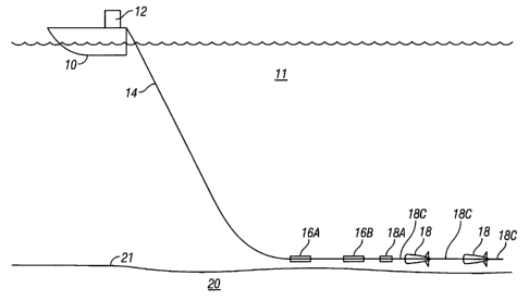
One embodiment of a marine controlled source electromagnetic survey system
according to the invention is shown in Figure 1. In the embodiment of Figure
1, an
electromagnetic field is imparted into the Earth's subsurface by generating a
time varying
electric field at a selected depth below the water surface. In the present
embodiment, the
electric field is generated by applying electric current across a pair of
spaced apart source
electrodes. In Figure 1, a survey vessel 10 moves along the surface of a body
of water 11
such as a lake or the ocean. The survey vessel 10 may include electronic
devices thereon,
shown collectively as a "recording system" 12 for imparting electrical survey
current into the
Earth formations 20 below the water bottom 21 through various electrodes. The
equipment
in the recording system 12 may also include devices (not shown separately) for
detecting and
recording signals corresponding to voltages detected across one or more pairs
of detectors 18
(shown in detail in Figure 2) each such detector having at least one electrode
thereon.
Equipment in the recording system 12 may also include devices (not shown
separately) for
determining the geodetic position of the vessel 10 and the various detectors
18 in the system.
The electrodes on the detectors 18 will be explained in more detail below with
reference to
Figure 2.
In the present embodiment, the electrical survey current may be imparted
through a
dipole pair of source electrodes 16A, 16B separated from each other by a
selected distance.
The selected distance will depend on, among other factors, the depth in the
Earth's subsurface
8
CA 02582882 2007-03-27
20 which is to be surveyed and the expected resistivities of the formations in
the Earth's
subsurface. The source electrodes 16A, 16B may be towed by a suitable survey
cable 14
deployed by the survey vessel 10 or by another vessel. The survey cable 14 may
include
electrical conductors (not shown separately) for transferring the electrical
survey current from
the recording unit 12 to the source electrodes 16A, 16B and for transferring
to the recording
system 12 signals related to voltages imparted across electrodes on pairs of
the various
detectors 18, as will be further explained below. Structures for the source
electrodes 16A,
16B are known in the art. The source electrodes 16A, 16B are shown in Figure 1
arranged as
a horizontal electric dipole. In other implementations, the source electrodes
may be arranged
as a vertical electric dipole.
In the present embodiment, the survey cable 14 may include at its aft end a
crossover
coupling and telemetry unit, shown generally at 18A. The crossover coupling
and telemetry
unit 18A in the present embodiment forms mechanical and electrical connection
between the
aft end of the survey cable 14 and to detector tow cables 18C for towing two
or more of the
detectors 18. The detectors 18 may be disposed along the detector tow cables
18C at spaced
apart locations as shown in Figure 1. The tow cables 18C in other embodiments
may be
coupled directly to the vessel 10. The number of and spacing of the detectors
18 used in any
particular embodiment of an electromagnetic survey system will depend on,
among other
factors, the resolution desired for the survey results, and the resistivities
of the formations in
the Earth's subsurface 20. The detectors 18 may be towed by the survey vessel
10 as shown
in Figure 1, or may be towed by a different vessel. The crossover coupling and
telemetry unit
18A may also include circuitry (not shown in Figure 1) for converting signals
related to the
detected voltages imparted across the various detectors 18 into an electrical
or optical
telemetry format for transmitting to the recording system 12, or may be a
simple mechanical
and electrical junction between the survey cable 14 and the detector tow
cables 18C.
Additionally or alternatively, the crossover coupling and telemetry unit 18A
may include
circuits (not shown) for locally recording signals corresponding to the
detected voltages.
In operating the system shown in Figure 1,= as the survey vessel 10 moves
through the
water 11, the recording system causes electrical survey current to be imparted
across the
source electrodes 16A, 16B. If the system is to measure transient
electromagnetic effects, the
electrical current may be switched direct current, alternating polarity direct
current, either
discretely switched or in a sequence such as a pseudo random binary. If the
system is to
9
CA 02582882 2007-03-27
measure frequency domain electromagnetic effects, the current may be
alternating current
having one or more frequencies in a range of about 0.1 to 100 Hz. The waveform
of the
alternating current may be sinusoidal, triangular, square wave or other
periodic waveform,
depending on the desired frequency content thereof. While, or after, the
source electrodes
16A 16B are so energized (depending on whether transient or frequency domain
effects are
being measured), voltages are measured across selected pairs of the detectors
18.
Measurements corresponding to the amplitude and/or phase of the induced
voltages (phase
with respect to the electrical current imparted across the source electrodes
16A, 16B), and/or
amplitude with respect to current switching time, are then used to infer the
structure and/or
composition of the subsurface 20. The detectors 18 may be towed at the same or
different
depth than the source electrodes 16A, 16B.
One embodiment of a detector 18 is shown in more detail in Figure 2. The
detector
18 may include a generally torpedo-shaped housing 32, preferably formed from
glass fiber
reinforced plastic or similar high strength, electrically non-conductive and
corrosion resistant
material. The housing 32 may include a generally blunt, rounded nose 31, onto
which a
sensing element, which in this embodiment is an electrode 30, is suitably
disposed thereon.
The electrode 30 may be formed from graphite or other electrically conductive,
non-metallic
material to avoid any changes in its electrical impedance caused by corrosion,
as would occur
with many metals if used for the electrode 30. The nose 31 will generally be
disposed within
laminar flowing water as the housing 32 is moved through the water. Thus, the
electrode 30
so positioned will be less susceptible to having turbulence-induced electrical
noise introduced
therein.
The housing 32 may include a generally elliptically shaped mid-section 40 and
a
generally conically shaped tail section 42. The shapes of the various sections
(nose 31, mid-
section 40 and tail 42) of the housing 32 are preferably such that the housing
32 may move
through the water (11 in Figure 1) with a minimum of hydrodynamic resistance,
induce as
little turbulence in the water as practical and provide a surface for the
electrode 30 that will
be disposed in substantially laminar flowing water.
Motion of the housing 32 through the water may be stabilized by coupling
generally
wing-shaped fins 34 at a suitable location along the housing 32. The fins 34
may be affixed
to the housing 32 or may be integrally formed therewith. The outermost edge of
each of the
fins 34 can also be the place at which the detector tow cables 18C are coupled
to the housing
CA 02582882 2007-03-27
32. As shown in Figure 2, the detector tow cables 18C may be affixed to the
outermost edges
of the fins 34 so as extend generally parallel to each other along the
direction of motion of the
detector tow cables 18C. The fins 34 are preferably symmetrically placed with
respect to the
housing 32 on opposed sides thereof. Although shown in Figure 2 as being
horizontally
separated, the detector tow cables 18C may also be vertically separated.
Horizontal
separation of the tow cables 18C may reduce induction noise caused by motion
of the tow
cables 18C within the Earth's geomagnetic field is electrically connected as
will be further
explained below with reference to Figure 3.
The housing 32 may also include two or more, generally circumferentially
symmetrically placed stabilizers 44 near the aft end of the housing 32. The
fins 34 and
stabilizers 44 may be integrally formed with the housing 32 or separately
formed and affixed
to the housing 32. In combination, the fins 34 and stabilizers 44 cause the
housing 32 to
move through the water with high directional stability. High directional
stability, among
other possible benefits, may reduce the amount of noise being induced in the
tow cables 18C
by undue movement of the tow cables 18C with respect to the Earth's
geomagnetic field.
The housing 32 may also be formed to define one or more sealed interior
compartments 33 including therein oil or similar electrically non-conductive,
substantially
incompressible fluid. The total volume of the compartments, and the density of
such fluid
(and the enclosed volume of a defined chamber that will be further explained
below) can be
selected to provide the housing 32 with substantially neutral buoyancy in the
water.
The housing 32 may also be formed to define a sealed interior chamber 35, in
which
suitable amplification and telemetry circuitry, shown generally at 36, may be
located. The
circuitry 36 is used to detect voltages imparted across the electrode 30 and
another, similarly
formed electrode in another one of the detectors 18 disposed along the
detector tow cables
18C. The circuitry 36 may be electrically connected to each of the detector
tow cables 18C
by suitable wiring, shown at 38. The circuitry 36 and the wiring 38 will be
explained in more
detail with reference to Figure 3.
The present embodiment includes two, symmetrically placed, substantially
coplanar
detector tow cables 18C coupled to respective ones of the fins 34 in order to
accomplish
several objectives. First, electrical power may be conducted to the circuits
36, signals may be
conducted from the circuits 36, and voltages or other representative signals
may be
transmitted along electrical conductors (see Figure 4) in the detector tow
cables 18C
11
CA 02582882 2007-03-27
substantially symmetrically, so as to avoid inducing stray voltages in the
electrode 30.
Second, the arrangement of the detector tow cables 18C as shown in Figure 2,
being
substantially coplanar and symmetric with respect to the detectors 18, may
improve the
stability of movement of the detector 18 through the water. Preferably the
detector tow
cables 18C have as small a diameter as is practical to reduce the effects of
any turbulence
induced by moving the detector tow cables 18C through the water. Additionally,
the use of
two detector tow cables is intended to substantially cancel out any voltages
that may be
induced in the detector tow cables 18C as a result of any motion instability
of the detectors 18
and detector tow cables 18C within the Earth's geomagnetic field, as explained
previously.
Preferably the detector tow cables 18C are as thin as practical with respect
to the drag
forces required to be carried by the tow cables 18C, not only to reduce drag,
as explained
above, but also to increase the vibration frequency of any turbulence-induced
vibration in the
tow cables 18C. Further, using thin tow cables minimizes their mass, thus
minimizing any
effects of the tow cables 18C on the motion of the detectors 18.
The embodiment shown in Figure 1 includes detectors arranged so that voltages
are
measured across a horizontal electrode pair. In other embodiments, one or more
of the
detectors may be arranged to measure voltage in a vertical or other
orientation using separate
tow cables and suitable structures for maintaining the relative positions of
the various
detectors.
One embodiment of the circuitry 36 is shown schematically in Figure 3. The
circuitry 36 may include a power converter 140 which accepts electrical power
from
conductors in the detector tow cables (18C in Figure 2) through suitable
symmetric
connections, such as electrical conductors 140A, 140B in the wiring 38. In a
preferred
embodiment direct current (DC) voltage is supplied by means of conductors 140A
and 140B,
and power converter 140 is a DC-DC converter. In an alternate embodiment
alternating
current (AC) power is supplied to the power converter 140 preferably at
relatively high
frequency, 500 Hz or more, so as to avoid inducing detectable voltages in the
electrodes (18
in Figure 2), and power converter 140 is an AC-DC converter. The power
converter 140 may
supply suitable electrical power to a preamplifier 142, an analog to digital
converter (ADC)
144 and a telemetry transceiver 146.
The preamplifier 142 has one input terminal electrically coupled to the
electrode (30
in Figure 2). The other input terminal of the preamplifier may be electrically
coupled, such
12
CA 02582882 2007-03-27
as through conductors 142A, 142B to a selected one of the electrodes (18 in
Figure 2)
disposed along the detector tow cables (18C in Figure 2). Output of the
preamplifier 142
may be digitized by the ADC 144, and conducted to the telemetry transceiver
146 for
inclusion in any suitable telemetry scheme. The telemetry transceiver may be
electrically
coupled to suitable conductors 146A, 146B in the wiring 38. The various
conductors 142A,
142B, 146A, 146B are coupled to corresponding conductors in the detector tow
cables 18C as
will be explained in more detail below with reference to Figure 4.
In some embodiments, a control signal may be transmitted to the telemetry
transceiver
146 (typically from the recording unit 12 in Figure 1) to cause the
preamplifier 142 to be
selectively coupled at the one input terminal to the conductors 142A, 142B,
such that the
voltage imparted to the input of the preamplifier 142 is between selected ones
of the detectors
(18 in Figure 1) along the detector tow cables (18C in Figure 1). Thus, the
spacing between
the detectors and corresponding electrodes thereon may be selectable in such
embodiments.
One embodiment of the crossover coupling and telemetry unit 18A is shown
schematically in Figure 4. The unit 18A may include a sealed, pressure
resistant housing
118A formed from steel or other high strength material. The housing 118A
includes load
transfer devices 114A to couple to one or more strength members 14A in the
survey cable 14
at the aft end thereof. The load transfer devices 114A couple the tension
carried by the
strength members 14A to the housing 118A. The housing 118A is preferably
arranged to
sealingly engage the survey cable 14 so as to exclude water from the interior
of both the
survey cable 14 and the housing 118A. Electrical and/or optical conductors
forming part of a
harness 14B pass through an opening into the interior of the housing 118A and
are
operatively coupled to respective power conductors 118C and telemetry
conductors 218C in
each of the detector tow cables 18C. Each detector tow cable 18C may include a
water
resistant exterior jacket 518C adapted to sealingly engage the housing 118A so
as to exclude
water from the interior of the housing 118A and each to cable 18C. Each
detector tow cable
can include a strength member 318C preferably formed from fiber rope such as a
fiber sold
under the trademark VECTRAN, which is a registered trademark of Hoechst
Celanese Corp.,
New York, New York. Each strength member 318C is coupled to a respective load
transfer
device 418C in the housing 118A to transfer tension load from the housing 118A
to each
detector tow cable 18C.
13
CA 02582882 2007-03-27
As previously explained, electromagnetic surveying known in the art includes
imparting time varying magnetic fields into the Earth's subsurface, and
detecting magnetic
fields that result from interaction of the imparted time varying fields with
the various
formations in the subsurface. Another embodiment of a system according to the
invention is
shown in Figure 5 which includes magnetic field generating and detecting
devices for such
purposes. Figure 5 shows a survey vessel 10 having a recording system 12
thereon moving
through a body of water 11, as explained above with reference to Figure 1. The
vessel 10
pulls a suitable survey cable 14 through the water 11. In the present
embodiment, a loop
antenna 17 is towed at the end of the survey cable 14. The loop antenna 17 can
be coupled to
a similar electric survey current source in the recording system 12 to that
explained with
reference to Figure 1. In the embodiment of Figure 5, as the current is passed
through the
loop antenna 17, a magnetic field is induced. The antenna 17 as shown in
Figure 1 produces
a vertical magnetic dipole, but other dipole orientations may be used in other
implementations.
At the aft end of the antenna 17, a crossover coupling and telemetry unit 18A,
similar
to that explained with reference to Figure 4, can be used to couple the end of
the survey cable
14 to tow cables 18C substantially as explained with reference to Figure 4.
The tow cables
18C are coupled to at least one detector 118, and preferably a plurality of
such detectors at
spaced apart locations along the tow cables (similar to what is shown in
Figure 1). The
detector 118 in Figure 5 may include one or more magnetic field sensor
elements
(magnetometers) therein, and may or may not include a galvanic electrode as
explained with
reference to Figure 2. The structure of the detector 118 may be substantially
similar to the
structure explained above with reference to Figure 2, in particular including
a housing
arranged to minimin generation of turbulence and to minimize motion thereof
other than
along the tow direction. The magnetometer, as will be explained below, detects
magnetic
fields resulting from interaction of the imparted electromagnetic field with
the subsurface 20
and generates corresponding signals that may be recorded in the recording
system 12 or
elsewhere for interpretation. Various aspects of the detected magnetic fields
are used to infer
structure of and composition of the various formations in the subsurface 20.
If
magnetometers are used in the present embodiment, it is preferable that the
detector housing
be made from a substantially non-magnetic material. The plastic compositions
explained
with reference to Figure 2 will of course have such properties. If an
electrode will not be
disposed on any part of the detector 118, the detector housing may be (but
need not be)
14
CA 02582882 2007-03-27
=
electrically conductive, although it should be non-magnetic. Materials such as
monel may be
used in such implementations. The present embodiment of the detector 118 may
include any
or all of the features of the housing explained above with reference to Figure
2 provided that
the detector 118 is arranged to minimize turbulence and motion other than
along the tow
direction.
Referring to Figure 6, circuitry 136 that may include one or more
magnetometers, can
be used in a detector as shown in Figure 5. Most of the components of the
circuitry 136 may
be substantially similar to the circuitry explained above with reference to
Figure 3, including
an ADC 144, preamplifier 142, power supply 140 and telemetry transceiver 146.
The present
embodiment may include one or more magnetometers, shown at Ml, M2, M3. The
magnetometers Ml, M2, M3 may be flux-gate devices such as are used to detect
the Earth's
geomagnetic field, or similar device. The magnetometers Ml, M2, M3 in Figure 6
may be
oriented substantially orthogonally with respect to each other for
convenience, or may be in
other orientations. The magnetometers Ml, M2, M3 have their signal outputs
coupled to
corresponding input terminals of a multiplexer 147 interposed between them and
the
preamplifier 142. The multiplexer 147 may include additional input terminals,
such as shown
at El coupled to one or more electrodes, if such are used in any particular
implementation. In
the present embodiment, both an electrode, as explained with reference to
Figure 2, and at
least one magnetometer may be used in the detector (118 in Figure 5).
The present embodiment of the detector (118 in Figure 5) may also be used with
the
electric field generating device shown in Figure 1. In such implementations,
the
magnetometers Ml, M2, M3 detect magnetic fields resulting from interaction of
the time
varying electric field with the various formations in the subsurface (20 in
Figure 1).
Irrespective of the particular implementation, whether electric fields are
generated and
voltages detected, or whether magnetic fields are induced and detected, or any
combination
thereof, by minimizing water turbulence and motion of the detector other than
along the tow
direction, noise detected by the sensing elements will be minimi7ed, which can
materially
enhance the ability to conduct an electromagnetic survey while moving the
detectors. Such
survey techniques may improve the speed and efficiency of electromagnetic
surveying.
While the invention has been described with respect to a limited number of
embodiments, those skilled in the art, having benefit of this disclosure, will
appreciate that
other embodiments can be devised which do not depart from the scope of the
invention as
CA 02582882 2007-03-27
disclosed herein. Accordingly, the scope of the invention should be limited
only by the
attached claims.
16