Language selection

Search

Patent 2583270 Summary

Third-party information liability

Some of the information on this Web page has been provided by external sources. The Government of Canada is not responsible for the accuracy, reliability or currency of the information supplied by external sources. Users wishing to rely upon this information should consult directly with the source of the information. Content provided by external sources is not subject to official languages, privacy and accessibility requirements.

Claims and Abstract availability

Any discrepancies in the text and image of the Claims and Abstract are due to differing posting times. Text of the Claims and Abstract are posted:

  • At the time the application is open to public inspection;
  • At the time of issue of the patent (grant).
(12) Patent Application: (11) CA 2583270
(54) English Title: SUBSEA FLUID DELIVERY SYSTEM AND METHOD
(54) French Title: SYSTEME ET PROCEDE DE DISTRIBUTION DE FLUIDE SOUS-MARIN
Status: Deemed Abandoned and Beyond the Period of Reinstatement - Pending Response to Notice of Disregarded Communication
Bibliographic Data
(51) International Patent Classification (IPC):
  • F04B 43/12 (2006.01)
  • F04B 07/02 (2006.01)
  • F04B 17/00 (2006.01)
  • F04B 49/00 (2006.01)
(72) Inventors :
  • CUNNINGHAM, MICHAEL (United States of America)
  • BLANCHARD, CHAD (United States of America)
  • SCHULTZ, EARL V., JR. (United States of America)
(73) Owners :
  • OCEANEERING INTERNATIONAL, INC.
(71) Applicants :
  • OCEANEERING INTERNATIONAL, INC. (United States of America)
(74) Agent: SMART & BIGGAR LP
(74) Associate agent:
(45) Issued:
(86) PCT Filing Date: 2005-10-06
(87) Open to Public Inspection: 2006-04-13
Examination requested: 2007-05-17
Availability of licence: N/A
Dedicated to the Public: N/A
(25) Language of filing: English

Patent Cooperation Treaty (PCT): Yes
(86) PCT Filing Number: PCT/US2005/035886
(87) International Publication Number: US2005035886
(85) National Entry: 2007-04-05

(30) Application Priority Data:
Application No. Country/Territory Date
60/616,240 (United States of America) 2004-10-06

Abstracts

English Abstract


A system for delivering fluids to a subsea device comprises a first fluid
pressurizer for pressurizing fluid at a first pressure in communication with a
fluid pressure intensifier located subsea that is capable of increasing the
fluid pressure of the fluid. It is emphasized that this abstract is provided
to comply with the rules requiring an abstract which will allow a searcher or
other reader to quickly ascertain the subject matter of the technical
disclosure. It is submitted with the understanding that it will not be used to
interpret or limit the scope of meaning of the claims.


French Abstract

L'invention concerne un système permettant de distribuer des fluides à un dispositif sous-marin. Ledit système comprend un premier dispositif de mise en pression fluidique permettant de mettre un fluide sous pression à une première pression en communication avec un multiplicateur de pression fluidique situé sous la mer capable d'augmenter la pression d'un fluide.

Claims

Note: Claims are shown in the official language in which they were submitted.

CLAIMS:
We claim:
1. A method of providing fluid under pressure for subsea use, comprising:
a. pumping a fluid at a first fluid pressure from a first location to a fluid
pressure
intensifier located subsea;
b. increasing the first fluid pressure to a higher fluid pressure at the fluid
pressure
intensifier located subsea; and
c. providing the higher fluid pressure fluid to a device for use subsea.
2. The method of claim 1, wherein the fluid is pumped at a first fluid
pressure from at
least one of (i) a pump located at a surface location or (ii) a pump located
subsea but not
located proximate the fluid pressure intensifier.
3. The method of claim 1, wherein:
a. the device is a component of a subsea installation workover control system;
and
b. the fluid is adapted to be used with the device for a subsea installation
workover control system function.
4. A system for providing fluid under pressure for subsea use, comprising:
a. a fluid source located distally from a seabed and adapted to provide a
fluid
suitable for use with a subsea device;
b. a fluid pressurizer in fluid communication with the fluid source, the fluid
pressurizer adapted to pressurize the fluid to a first pressure;
c. a fluid pressure intensifier located subsea, the fluid pressure intensifier
further
adapted to receive the fluid at the first fluid pressure and output the fluid
at a
fluid pressure higher than the first fluid pressure; and
5

d. a fluid conduit in fluid communication in between the fluid pressurizer and
the
fluid pressure intensifier.
5. The system of claim 4, wherein the subsea device is adapted to provide a
predetermined installation workover function.
6. The system of claim 4, wherein the fluid is at least one of (i) a control
fluid or (ii) a
tree chemical fluid.
7. The system of claim 4, wherein the fluid pressurizer is adapted to provide
fluid at a
fluid pressure substantially lower than the delivery pressure required for
injection of fluid to a
subsea device.
8. The system of claim 4, wherein the fluid pressurizer is located at least
(i) proximate
the surface or (ii) subsea distally from the fluid pressure intensifier.
9. The system of claim 4, wherein the fluid pressure intensifier is adapted to
provide a
pressure substantially higher than 10,000 PSI.
10. The system of claim 4, further comprising a surface control panel
operatively in
communication with at least one of (i) the fluid pressurizer or (ii) the fluid
pressure
intensifier.
11. The system of claim 4, wherein the fluid conduit is an umbilical.
12. The system of claim 11, wherein the umbilical further comprises at least
one of (i) a
fluid conduit, (ii) an electrical power conduit, and (iii) a data conduit.
13. The system of claim 4 the fluid pressure intensifier comprises a plurality
of fluid
pressure intensifiers.
14. The system of claim 13, wherein a first of the plurality of fluid pressure
intensifiers is
fluidly connected to at least one other of the plurality of fluid pressure
intensifiers.
15. The system of claim 13, wherein the plurality of fluid pressure
intensifiers are fluidly
interconnected in at least one of a series or parallel fluid connection.
6

16. A system for providing an installation workover control system,
comprising:
a. a fluid source located distally from a seabed and adapted to provide a
fluid
suitable for use with a subsea installation workover function;
b. a fluid pressurizer in fluid communication with the fluid source, the fluid
pressurizer adapted to pressurize the fluid to a first pressure;
c. a fluid pressure intensifier located at a surface location, the fluid
pressure
intensifier further adapted to receive fluid at a first fluid pressure and
output
the fluid at a fluid pressure higher than the first fluid pressure; and
d. a fluid conduit in fluid communication with the fluid pressurizer and the
fluid
pressure intensifier.
17. The system of claim 16, wherein the fluid pressure intensifier is adapted
to be driven
hydraulically from the surface.
7

Description

Note: Descriptions are shown in the official language in which they were submitted.


CA 02583270 2007-04-05
WO 2006/039719 PCT/US2005/035886
Title of Invention: Subsea Fluid Delivery System And Method
Inventors: Michael Cunningham; Chad Blanchard
FIELD OF THE INVENTION
[0001] The inventions relate to a system and method for delivering fluid under
pressure for use subsea.
BACKGROUND OF THE INVENTION
[0002] Subsea devices often require fluids, e.g. hydraulic fluids or chemicals
for
injection and the like. These fluids are typically delivered to the device
under pressure. As
subsea devices are deployed deeper and deeper, the pressures required have
increased.
[0003] Existing installation workover control systems are limited in the
projects on
which they can be used, in part due to the pressure ratings of umbilicals used
to provide fluids
under pressure from a source of fluids, e.g. a surface vessel, to devices
subsea that need that
fluid. Deepwater trees, for example, will or currently need fluid pressures in
the ranges that
exceed 10,000 psi.
[0004] Additionally, umbilicals from the surface currently need to contain a
plurality
of fluid conduits which increases cost and complexity. The greater the number
of required
conduits, the greater the cost associated with the umbilical.
BRIEF DESCRIPTION OF THE DRAWINGS
[0001] The various drawings supplied herein are representative of one or more
embodiments of the present inventions.
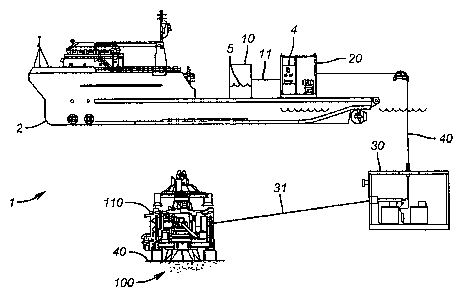
[0002] Fig. 1 is a planar view in of an exemplary system;
[0003] Fig. 2 is a cross-sectional view of an exemplary conduit;
[0004] Fig. 3 is a planar view of a second exemplary system; and
[0005] Fig. 4 is a flowchart of an exemplary method.

CA 02583270 2007-04-05
WO 2006/039719 PCT/US2005/035886
DETAILED DESCRIPTION OF
EXEMPLARY EMBODIMENTS OF THE INVENTIONS
[0005] Referring now to Fig. 1, system 1 is adapted to provide fluid under
pressure to
a subsea device, e.g. a device adapted for use in an installation workover
control system. In a
preferred embodiment, system 1 comprises fluid source 10 located distally from
seabed 100
and adapted to provide fluid 5 suitable for use with the subsea device, e.g.
to provide a subsea
installation workover function; fluid pressurizer 20 in fluid coinmunication
with fluid source
10, fluid pressurizer 20 adapted to pressurize fluid 5 to a first pressure;
fluid pressure
intensifier 30 adapted to be located subsea, fluid pressure intensifier 30
further adapted to
receive fluid 5 at a first fluid pressure and output fluid 5 at a fluid
pressure higher than the
first fluid pressure; and fluid conduit 40 in fluid communication with fluid
pressurizer 20 and
fluid pressure intensifier 30.
[0006] Fluid source -10 may be located on vessel 2 but does not have to be. In
a
preferred embodiment, fluid source 10 is located distally from seabed 100 such
as near or at
the water surface. Fluid 5 may be a control fluid, a tree chemical fluid, or
the like, or a
combination tliereof.
[0007] Fluid pressurizer 20 is adapted to provide a pressure substantially
lower than
the delivery pressure required for injection of fluid 5 to subsea device 110.
Fluid pressurizer
20 may be located proximate the surface or subsea distally from fluid pressure
intensifier 30
and may be part of fluid source 10, i.e. integrated with fluid source 10, or
otherwise in fluid
communication with fluid source 10 such as via fluid conduit 11.
[0008] Fluid pressurizer 20 is in fluid communication with fluid pressure
intensifier
30, which is located proximate seabed 100, such as via fluid conduit 40. In
preferred
embodiments, fluid pressure intensifier 30 may be located on seabed 100 or
near seabed 110
such as on an ROV (not shown in the figures). Fluid pressurizer intensifier 30
is adapted to
provide fluid 5 to one or more subsea devices, e.g. subsea device 110, at
higher fluid pressure
2

CA 02583270 2007-04-05
WO 2006/039719 PCT/US2005/035886
than fluid pressurizer 20 provides. In an embodiment, fluid pressure
intensifier 30 is adapted
to provide a pressure substantially higher than 10,000 PSI and, more
preferably, in the range
of around 15,000 to around 20,000 psi.
[0009] In certain embodiments, fluid pressure intensifier 30 comprises a
plurality of
fluid pressure intensifiers 30 connected in series, parallel, or a combination
thereof. One or
more fluid pressure intensifiers 30 may utilize proportional hydraulic valves.
[0010] In a preferred embodiment, fluid conduit 40 is an umbilical which may
further
corri-prise one or more fluid conduits 42, electrical power conduits 43, data
conduits 44, or a
coinbination thereof.
[0011] System 1 may further comprise surface control panel 4 operatively in
communication with fluid pressurizer 20, fluid pressure intensifier 30, or
both.
[0012] In an alternative embodiment, system 1 is adapted to provide an
installation
workover control system and comprises fluid source 10 located distally from
seabed 100 and
adapted to provide fluid 5 suitable for use with a subsea installation
workover function; fluid
pressurizer 20 in fluid communication with fluid source 10, fluid pressurizer
20 adapted to
pressurize fluid 5 to a first pressure; fluid pressure intensifier 30 located
at a surface location,
fluid pressure intensifier 30 further adapted to receive fluid 5 at a first
fluid pressure and
output fluid 5 at a fluid pressure higher than the first fluid pressure; and
fluid conduit 40 in
fluid communication with fluid pressurizer 20 and fluid pressure intensifier
30. '
[0013] Fluid pressure intensifier 30 may be further adapted to be driven
hydraulically
frorn the surface.
[0014] In the operation of an exemplary embodiment, fluid under pressure may
be
provided for subsea use such as with a subsea installation workover control
system by
purnping fluid 5 at a first fluid pressure from a first location to fluid
pressure intensifier 20
3

CA 02583270 2007-04-05
WO 2006/039719 PCT/US2005/035886
located subsea; increasing the fluid pressure to a higher pressure at the
subsea fluid pressure
intensifier 20; and providing the increased pressure fluid 5 for use subsea.
[0015] In an einbodiment, fluid 5 is pumped at a first fluid pressure from a
pump
located at a surface location or a pump located subsea, e.g. fluid pressurizer
20, but not
located proximate fluid pressure intensifier 30.
[0016] The foregoing disclosure and description of the inventions are
illustrative and
explanatory. Various changes in the size, shape, and materials, as well as in
the details of the
illustrative construction and/or a illustrative method may be made without
departing from the
spirit of the invention.
4

Representative Drawing
A single figure which represents the drawing illustrating the invention.
Administrative Status

2024-08-01:As part of the Next Generation Patents (NGP) transition, the Canadian Patents Database (CPD) now contains a more detailed Event History, which replicates the Event Log of our new back-office solution.

Please note that "Inactive:" events refers to events no longer in use in our new back-office solution.

For a clearer understanding of the status of the application/patent presented on this page, the site Disclaimer , as well as the definitions for Patent , Event History , Maintenance Fee  and Payment History  should be consulted.

Event History

Description Date
Application Not Reinstated by Deadline 2010-08-17
Inactive: Dead - No reply to s.30(2) Rules requisition 2010-08-17
Deemed Abandoned - Failure to Respond to Maintenance Fee Notice 2009-10-06
Inactive: Abandoned - No reply to s.30(2) Rules requisition 2009-08-17
Inactive: S.30(2) Rules - Examiner requisition 2009-02-17
Letter Sent 2007-12-07
Inactive: Single transfer 2007-10-10
Correct Applicant Request Received 2007-10-10
Letter Sent 2007-06-19
Inactive: Cover page published 2007-06-11
Inactive: Incomplete PCT application letter 2007-06-07
Inactive: Notice - National entry - No RFE 2007-06-07
Request for Examination Requirements Determined Compliant 2007-05-17
All Requirements for Examination Determined Compliant 2007-05-17
Request for Examination Received 2007-05-17
Inactive: First IPC assigned 2007-05-01
Application Received - PCT 2007-04-30
Inactive: IPRP received 2007-04-06
National Entry Requirements Determined Compliant 2007-04-05
Application Published (Open to Public Inspection) 2006-04-13

Abandonment History

Abandonment Date Reason Reinstatement Date
2009-10-06

Maintenance Fee

The last payment was received on 2008-09-30

Note : If the full payment has not been received on or before the date indicated, a further fee may be required which may be one of the following

  • the reinstatement fee;
  • the late payment fee; or
  • additional fee to reverse deemed expiry.

Patent fees are adjusted on the 1st of January every year. The amounts above are the current amounts if received by December 31 of the current year.
Please refer to the CIPO Patent Fees web page to see all current fee amounts.

Fee History

Fee Type Anniversary Year Due Date Paid Date
Basic national fee - standard 2007-04-05
Request for examination - standard 2007-05-17
MF (application, 2nd anniv.) - standard 02 2007-10-09 2007-09-19
Registration of a document 2007-10-10
MF (application, 3rd anniv.) - standard 03 2008-10-06 2008-09-30
Owners on Record

Note: Records showing the ownership history in alphabetical order.

Current Owners on Record
OCEANEERING INTERNATIONAL, INC.
Past Owners on Record
CHAD BLANCHARD
EARL V., JR. SCHULTZ
MICHAEL CUNNINGHAM
Past Owners that do not appear in the "Owners on Record" listing will appear in other documentation within the application.
Documents

To view selected files, please enter reCAPTCHA code :


To view images, click a link in the Document Description column. To download the documents, select one or more checkboxes in the first column and then click the "Download Selected in PDF format (Zip Archive)" or the "Download Selected as Single PDF" button.

List of published and non-published patent-specific documents on the CPD .

If you have any difficulty accessing content, you can call the Client Service Centre at 1-866-997-1936 or send them an e-mail at CIPO Client Service Centre.


Document
Description 
Date
(yyyy-mm-dd) 
Number of pages   Size of Image (KB) 
Drawings 2007-04-04 3 66
Claims 2007-04-04 3 98
Description 2007-04-04 4 158
Abstract 2007-04-04 1 63
Representative drawing 2007-06-07 1 11
Acknowledgement of Request for Examination 2007-06-18 1 177
Reminder of maintenance fee due 2007-06-06 1 112
Notice of National Entry 2007-06-06 1 195
Courtesy - Certificate of registration (related document(s)) 2007-12-06 1 105
Courtesy - Abandonment Letter (R30(2)) 2009-11-08 1 163
Courtesy - Abandonment Letter (Maintenance Fee) 2009-11-30 1 172
PCT 2007-04-04 1 49
Correspondence 2007-06-06 1 17
Correspondence 2007-08-26 1 26
Correspondence 2007-10-09 2 102
PCT 2007-04-05 4 195
Fees 2008-09-29 1 35