Note: Descriptions are shown in the official language in which they were submitted.
CA 02583339 2007-04-11
- ~ _
LID-EQUIPPED, MONOMATERIAL CONTAINER FOR
HORTICULTURAL USE
DESCRIPTION
OBJECT OF THE INVENTION
This invention covers a box of the type used in marketing fruit and
vegetable produce, specifically a box made of medium or high density wood
fibre or some other similar product, incorporating holes to facilitate
aeration
of the product that it contains.
The purpose of the invention is to provide a package able to
withstand heavy loads, made of a single recyclable material, which can be
transported dismantled and is easy to assemble, with no need for staples,
nails
or any kind of adhesive, facilitating its stacking and providing optimum
ventilation of the products kept inside it.
BACKGROUND OF THE INVENTION
The usage of cardboard boxes for storing and transporting fruit
and vegetable produce is well known. Although these have the advantage of
being able to be stored dismantled, taking up the least space possible, such
boxes involve the disadvantage of having very low structural rigidity, which
is why they cannot be used for storing excessively heavy products, apart from
entailing the further problem of a major drop in their structural rigidity in
the
CA 02583339 2007-04-11
-2-
presence of humidity.
Wooden boxes are also often used for this type of products.
Although they have greater structural rigidity, to be assembled they require
staples, nails or some kind of adhesive complicating the construction process,
which results in making the final product more expensive.
This type of boxes also has the added problem of being difficult to
recycle, due to the presence of said staples or nails, whose elimination in
the
recycling process becomes complicated, to such an extent that there are
countries which do not allow in boxes with staples.
Apart from this, in a large number of countries the use of wooden
boxes is covered by certain legislation forcing said wood to be treated to be
free of pests, with the corresponding certificate vouching for this, though
this
is not always complied with.
This type of boxes involves the further problem of being supplied
assembled, consequently using up the space available, with the economic
repercussions that this has.
Lastly, cardboard and wooden boxes are also known of with holes,
slits or slots in their sides to improve their preservation condition by
aeration.
This solution is valid for vertically stacking boxes, but when space reasons
mean that several piles of boxes are stacked beside each other, forming
several rows, the boxes located on the outside make it impossible to air the
other boxes, as they cover these completely, with the resulting damage for the
products stored.
CA 02583339 2007-04-11
-3-
DESCRIPTION OF THE INVENTION
The single-material package for containing fruit and vegetable
produce with a lid as proposed in this invention is intended to provide an
entirely satisfactory solution to the problems stated above, being made up of
six pieces of "MDF" medium or high density wood fibre or some other
similar product. These pieces consist of a bottom, two sidepieces, two ends
and a top or lid. All these pieces can be easily fitted together with no need
for nails, staples nor any kind of adhesive.
The bottom consists of a basically rectangular piece with
chamfered corners, a plurality of holes of different radiuses, evenly
distributed across its surface, as well as a series of slots longitudinally
spread
along its smaller sides, with a plurality of trapezium-shaped tabs emerging
from its larger edges to assemble the side pieces to said bottom easily.
The side pieces consist of a basically rectangular body, with a
broad notch in its upper side, to facilitate aeration of the contents of the
box,
with chamfered lower edges, and a plurality of slots at both side and bottom
edges positionally coinciding with the tabs emerging from the larger edges of
the bottom, in the case of the lower edge, and with the tabs emerging from the
box ends, as will be described below.
The box end pieces consist of a basically rectangular body, with
chamfered lower edges, incorporating in their lower edge a plurality of
trapezium-shaped tabs, of the same kind as the ones emerging from the longer
sides of the bottom. In their side edges there are a number of trapezium-
CA 02583339 2007-04-11
-4-
shaped tabs, in whose lower edge there is a small notch which thus forms a
tooth for tongue and groove-type coupling with the side pieces by sliding in
under pressure, with said side edge having a wedge that makes it impossible
to pull out the box end after being coupled to the slot. They also have the
usual oval-shaped holes in the middle upper side like handles, having a small
extension or tab in the middle of the upper edge, for coupling the top.
This top, with a basically rectangular shape, and coinciding with
the mouth of the box, has a number of holes, for proper aeration of the
product inside, as well as to help viewing the contents, having two appendices
for coupling to the aforementioned oval holes in the box ends in the middle
zone of its shorter sides, so that after being attached, this top can also be
used
as a handle for the box, by means of its holes.
Both the box sides and the ends have triangular-shaped extensions
or appendices on their upper edges. These extensions facilitate perfect
vertical
stacking of the boxes, when these have not been placed in perfect alignment
for some reason, as the rounded lower edges of both the ends and the sides
coincide with the sloping edges of these extensions, the upper box sliding on
said sloping surface to its proper position by its own weight.
To get greater stability in stacking, the box ends have in turn a
number of trapezium-shaped tabs along their upper edges, spaced out in such
a way as to constitute a tongue and groove coupling with the tabs of the lower
bottom securing edge of the end belonging to the box immediately above.
DESCRIPTION OF THE DRAWINGS
CA 02583339 2007-04-11
-5-
To complement the description being given herein, in order to
ensure better understanding of the characteristics of the invention,
according to a preferential example of its practical execution, a set of
drawings is included as full part of this description, in which the following
items are shown, for illustration purposes and without constituting any
limitation:
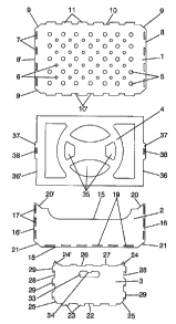
Figure 1.- This figure shows an exploded plan view of a box for
fruit and vegetable produce, made according to the object of this invention.
Figure 2.- Shows a plan view of the tabs for coupling the base to
the sides.
Figure 3.- Shows a perspective view of the box in an intermediate
phase of the assembly.
Figure 4.- Shows a perspective view of the assembled box without
its lid.
Figure 5.- Shows a perspective view of the assembled box with its
lid.
Figure 6.- Shows an elevation view of a detail of the prior
assembly of the box ends to the sides.
Figure 7.- Shows an elevation view of a detail of the final
arrangement of the assembly tabs in the top area of the box ends to the sides.
Figure 8.- Shows an elevation view of a set of boxes stacked in
CA 02583339 2007-04-11
-6-
several rows.
Figure 9.- Shows a plan view of a set of boxes stacked in several
rows.
PREFERENTIAL EXECUTION OF THE INVENTION
In view of the figures referred to, and particularly Figure 1, it can
be seen how the box for fruit and vegetable produce proposed by the
invention consists basically of a bottom (1), two sides (2) (2'), two ends
(3),
(3') and a lid (4), all being able to be coupled together.
The bottom (1) consists of a basically rectangular body, fitted with
a plurality of circular holes (5) and (6), of greater and small diameter
respectively, spaced out over its surface area, as well as a series of slots,
(7),
longitudinally distributed along its lower edges (8), (8) for tongue and
groove
coupling to the ends (3), (3'). The bottom (1) also has four chamfered corners
(9) and a plurality of tabs (11) emerge from its larger sides (10), (10') for
tongue and groove coupling to the sides (2), (2'), in a coupling arrangement
which will be explained below.
These tabs (11) have a trapezium shape with a chamfered
presentation zone (12) with its edges rounded off, this zone helping to
position it against the corresponding slot, an expansion zone (13), of
slightly
greater length than that of said slot and an inverse trapezium-shaped zone
(14), with a transversal length equal to the thickness of the part that
receives
this, having in its narrowest longitudinal zone the same longitudinal
coordinate as the receiving slot, as can be seen in Figure 2.
CA 02583339 2007-04-11 -7-
The sides (2), (2') consist of a basically rectangular body, with the
traditional notch (15) in its upper larger side, this being a rectangular
notch,
with its edges extremely rounded off to get greater aeration of the product
housed inside the box.
On both smaller sides (16), (16') the box sides (2), (2') incorporate
a number of slots (17), as well as in their lower edge (18), given reference
(19) for its respective assembly with the ends (3), (3') and the bottom (1).
Furthermore, two triangular extensions (20), (20') emerge from
the ends of these sides (2), (2'), the extensions' inclination coinciding with
the inclination of both chamfered lower corners (21), (21').
The ends (3), (3') have an essentially rectangular body, provided
in its lower edge area (22) with a plurality of tabs (23), of the same kind as
the
ones present in the upper edges (10), (10') of the bottom (1).
From the ends of said box ends (3), (3') there emerge two
triangular extensions (24), (24') whose inclination coincides with the
inclination of both chamfered lower corners (25), (25'). A self-stacking
effect
is achieved by means of these and the triangular extensions (20), (20') fitted
on the box sides (2), (2'), as well as their chamfered corners (21), (21'), so
that if the upper box has not been placed properly, this will slide down under
its own weight onto said sloping surfaces until the proper position is
reached.
To ensure greater stability of the stacked boxes, the box ends (3),
(3') incorporate in turn at their upper edge (26), a number of tabs (27), of
trapezium shape, spaced out in such a way that these form a tongue and
groove coupling with the surface of the tabs (23) of the box end, which stand
CA 02583339 2007-04-11
-8-
out from the lower side of the bottom (1).
At both lateral edges (28), (28') the box ends (3), (3') incorporate
a number of trapezium-shaped tabs (29) in whose lower edge these have a
small notch (30), with the same width as the thickness of the sides (2), (2').
This notch (30) generates a tooth (31), for tongue and groove coupling with
the box sides (2), (2') through its holes (17).
As can be seen in Figure 3, for assembling the box, the procedure
involves placing the sides opposite each other (2), (2') with the larger sides
(10), (10') of the bottom (1). Then the box ends (3), (3') are placed on the
lower sides (8), (8') of the bottom (1), the four pieces thus being presented,
after which the sides (2), (2') are fitted to the bottom (1), inserting the
tabs
(11) by elastic deformation into the slots (19), and at the same time
inserting
the tabs (29) of the ends (3), (3') into the slots (17) in the box sides.
After inserting the tabs (29), these are locked in by means of
vertical downward movement, applying a certain pressure on the box end,
elastically deforming a small wedge (32), located beside the tab closest to
the
upper end of the edges (28), (28'), so that after fitting this wedge into the
slot
(17), this prevents any upward vertical movement of the box end, preventing
it from being pulled out, as can be seen in Figures 6 and 7.
The pressure applied as above is made use of to lock the tabs (23)
of the lower edge of the box end in the slots (7) present in the smaller edges
(8), (8') of the bottom (1) in the same movement, the box ending up properly
assembled, except for the top, without the use of any kind of adhesive,
staples
or nails being necessary for this.
CA 02583339 2007-04-11
-9-
In their upper middle zone the box ends (3), (3') have the
traditional oval-shaped hole (33), used as a handle, which has in its upper
middle zone a small tab (34) for coupling the lid (4).
As can be seen in Figures 1 and 5, the lid (4) has a basically
rectangular surface, with a number of holes (35) for proper aeration of the
product inserted, as well as for facilitating the vision of the contents
inside.
In the middle zone of its shorter sides (36), (36') this lid (4) has
certain extensions (37), which incorporate slots (38) for coupling this to the
box, so that after facing the lid (4) towards the mouth of the box, by means
of
a small elastic deformation of this, the extensions (37) are inserted through
the oval-shaped holes (33) in the box ends (3), (3'), the tab (34) being
coupled
in the slot (38).
This thus means that the lid has the effect of holding back the
products contained in the box, if this should tip over, and this lid can be
used
as a handle by means of the holes (35).
As can be seen in Figures 8 and 9, the projections (39) of the tabs
(29) in the box ends, as well as the distance between the slots (17) and the
edge of the side pieces (16), (16'), constitute a spacer between boxes,
preventing the surfaces of the boxes from coming into contact with each
other, when these are placed in a compact pallet arrangement, facilitating
the circulation of air between the interior boxes through the holes (41)