Note: Descriptions are shown in the official language in which they were submitted.
CA 02583612 2007-04-12
WO 2006/043923 PCT/US2004/033795
DEVICE FOR HIGH-HEELED SHOES AND
METHOD OF CONSTRUCTING A HIGH-HEELED SHOE
The present invention relates to a shoe that is easily constructed and
provides
greater comfort to the wearer without affecting the fit or style of the shoe.
The invention
has particular utility in connection with high-heeled shoes.
Conventional high-heeled shoes have a reputation for being extremely
uncomfortable. There is survey information indicating that as many as 20% of
the users
of such shoes experience foot pain related to the shoes immediately, and the
majority of
users experience such pain after as little as four hours of use.
In order to understand the prior art and the present invention, it is
necessary to
understand the anatomy of the foot and the basics of shoe construction. To
that end,
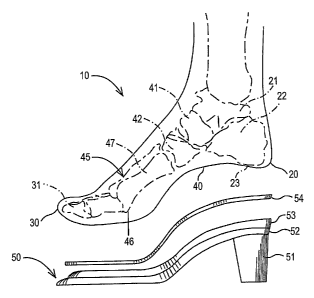
FIG. 1 is a diagrammatic view of the bones of the foot and the portions of a
shoe that
underlie the sole of the foot. By reference to FIG. 1, the following briefly
describes the
anatomy of the foot and the basics of shoe construction.
FIG. I is a diagrammatic medial side view of the bones of the human foot 10.
For purposes of this application, references to rearward mean in the direction
of the rear
of the foot or heel 20; references to forward mean in the direction of the
front of the foot
30 where the toes or phalanges 31 are located; references to medial mean the
side of the
foot where the arch 40 is located; references to lateral mean the outside of
the foot; and
references to upper or top and lower, bottom or under assume the foot or shoe
is oriented
in an upright position.
The heel 20 (also known as the tarsus) includes the talus 21 and the calcaneus
22
bones. The rear lower.surface of the calcaneus 22 has a slight protuberance 23
Icnown as
the tuberosity of the calcaneus. The bones of the foot also include the
navicular 41, the
cuneiform 42, the metatarsals 45 and the phalanges, or toes, with the big toe
31 visible in
FIG. 1. The metatarsal heads 46 are located at the forward end of the
metatarsal shafts
47. The metatarsals are numbered 1 to 5, with 1 designating the big toe.
Also depicted in FIG. 1 is a partially exploded view of the portions of a
conventional high-heeled shoe 50 that underlie the sole of the foot. Shoe 50
has a heel
51 which is generally attached to the lower surface of sole 52 of shoe 50,
with the sole 52
in turn supporting the insole board 53 on which the sock liner 54 is placed.
In a
conventional shoe, the insole board is typically of relatively rigid
construction from the
region underlying the wearer's heel to the heads of the metatarsals. Soclc
liners are
CA 02583612 2007-04-12
WO 2006/043923 PCT/US2004/033795
commonly very flexible and generally are very thin, typically no more than
half a
millimeter thick. The sock liner is the surface upon which the sole of the
foot normally
rests.
According to conventional shoe construction methods, the last is the form
around
which the shoe is constructed. During manufacture, the lower surface of the
last sits on
the upper surface of insole board, and the shoe upper is then shaped around
the last and
attached to the insole board. Optimally, the lower surface of the last and the
upper
surface of the insole board fit together smoothly in order to properly
manufacture shoes.
If there is any convexity on the lower surface of the last or the upper
surface of the insole
board respectively, a corresponding concavity must be present in the insole
board or last
respectively. To be assured of a quality shoe construction, any such convexity
and
corresponding concavity must be carefully aligned during shoe manufacture,
thereby
introducing added complexity and/or quality control issues to shoe
manufacture.
As will be appreciated, a conventional high-heeled shoe such as shown in FIG.
1
places the wearer's foot essentially on an inclined plane. As a result, the
foot is urged
forward by gravity into the toe box in standing or walking. This results in
pressure on
the ball or forefoot regions and toe jamming which often gives rise to a
burning sensation
in these areas of the foot, as well as fatigue and discomfort in the foot and
other areas of
the body.
Numerous suggestions have been made for improving the comfort of high-heeled
shoes, including suggestions in my prior patents and publications. For
example, in a
February 1990 article in Current Podiatric Medicine, pp. 29-32, I described a
high-
heeled shoe design in which the portion of the shoe under the heel does not
form a
continuous ramp down the arch to the ball of the foot, but rather the portion
underlying
the heel is relatively parallel to the ground. The design used a rigid plastic
molded
midsole which was cupped to receive the heel and angled to bring the heel into
a plane
more parallel with the floor. In addition, a metatarsal pad was incorporated
into the
molded midsole.
In U.S. Patent No. 5,373,650, I proposed an orthotic under the heel. The
orthotic
is a rigid or semirigid shell under the heel and extending forward, with arch
support, to a
point behind the metatarsal heads of the foot. The heel in this device is
supported
parallel to the ground or tilted slightly baclcwards.
In U.S. Patent No. 5,782,015, I have described a high-heeled shoe design in
which the heel is positioned more parallel or slightly downwardly inclined
angle relative
2
CA 02583612 2007-04-12
WO 2006/043923 PCT/US2004/033795
to the shank plane and which has an arch support that supports the head of the
navicular
in approximately the same plane as the wearer's heel bones. My PCT Publication
W098/14083, published April 9, 1998, describes a rigid molded device
comprising a
heel cup and an anatomically shaped arch appliance.
Nuinerous examples of designs by others intended to improve comfort of high-
heeled shoes exist in the prior art. U.S. Patent Nos. 1,864,999, 1,907,997,
4,317,293,
4,631,841, 4,686,993, 4,932,141 and 6,412,198 each describes shoe inserts or
orthotics
intended to improve comfort of a high-heeled shoe. Several involve arch
supports.
Some are rigid; others suggest cushioning as a means to improve comfort. The
prior art
inserts and orthotics typically are relatively bulky and can affect a shoe's
fit if added by
the wearer after manufacture. Other prior art proposals to improve wearer
comfort
require that each last used to manufacture the shoe be modified to change the
shape of
the shoe itself.
These prior art constructions improve comfort by supporting or cushioning
parts
of the foot and/or altering the foot angles to reduce sliding forward and/or
to alter the
percentage of the wearer's weight borne by different parts of the foot. Their
teachings
suggest, among other things, placing the heel on a more level plane to shift
the weight
backward onto the heel, supporting the arch, angling the toes upward and/or
cushioning
the surfaces on which the largest percentage of weight is borne.
The present invention provides a thin flexible shoe insert which can readily
be
adapted to any style shoe and which can be incorporated into a shoe without
requiring
modifications to a shoe last, and the accompanying manufacturing complexity.
The
insert has two slightly raised areas under the heel and the metatarsals.
Although the
insert has two only slightly raised areas, it significantly increases wearer
comfort even in
very high heels. The insert does not require that the heel be repositioned to
a plane
parallel with the floor as is the case in some of the prior art. Other than in
the two
slightly raised areas, the insert can be extremely thin, thereby minimizing
any effect on
fit of the shoe and eliminating any adverse effect on the style or appearance
of the shoe.
Alternatively, the thin flexible insert can be placed in the shoe by the
wearer.
In accordance with the present invention, there is provided a device for
insertion
into a high-heeled shoe and a corresponding method of constructing shoes using
the
device. The device comprises (a) a rear region positioned to underlie the
calcaneus in at
least the area forward of the tuberosity of the calcaneus, the upper surface
of said rear
region having a portion which gradually rises from the rear of the device to a
crescent
3
CA 02583612 2007-04-12
WO 2006/043923 PCT/US2004/033795
shaped apex, said apex lying under the area forward of the tuberosity of the
calcaneus
and (b) a forward region positioned to underlie at least a portion of the
shafts of the
metatarsals, the upper surface of said forward region having a portion which
gradually
rises to an apex positioned to underlie the shafts of the second and third
metatarsals. In
the preferred embodiment, the device has a bridging or middle region which
connects
said forward and rear regions, the device is flexible and the upper surface of
the device
is smoothly contoured between all regions. A feature and advantage of the
device of the
present invention is that the device may be universally applied to
conventional high-
heeled shoes without the need to otherwise modify the shoes or the shoe last.
A shoe
may be constructed with the device according to the present invention by
incorporating
the device into the shoe during the manufacturing process or the device may be
applied
post-manufacture by the wearer.
FIG. I is a diagrammatic cross-sectional view of the foot bones and a
partially
exploded view of the portions of a conventional high-heeled shoe that underlie
the sole
of the foot.
FIG. 2 is a top plan view of an embodiment of the device of the present
invention.
FIG. 3 is a side cross-sectional view of the device of the present invention
shown
in FIG. 2, taken along plane "III-III."
FIG. 4 is a side cross-sectional view of the device of FIG. 2, taken along
plane
"Iv-Iv."
FIG. 5 is a diagrainmatic cross-sectional view of the foot bones and a
partially
exploded view of the portions of a conventional high-heeled shoe that underlie
the sole
of the foot into which the device of the present invention shown in FIG. 2 has
been
inserted.
FIG. 6 is a plan view of an alternative embodiment of the invention.
In the present invention, a device is provided which improves comfort and is
easily installed in high-heeled shoes. For purposes of this invention, it is
to be
understood that high-heeled shoes include all footwear having a heel which is
about one
inch or higher. The benefits of the invention are achieved when a raised area
is
positioned in a shoe to underlie the metatarsal shafts and heel. Typically,
the device of
the invention is positioned on the insole board or sock liner of a high-heeled
shoe.
Preferably, the device is sufficiently flexible so that it readily conforms to
the upper
surface of the insole board or sock liner on which it is positioned. It may be
formed of
4
CA 02583612 2007-04-12
WO 2006/043923 PCT/US2004/033795
any materials known to those of ordinary skill in the art that can be molded
or shaped
and that will produce a device flexible under normal conditions of use of a
shoe, while
retaining sufficient dimensional stability to retain the benefit of the
invention.
In the preferred embodiment, the device is shaped to underlie at least (i) the
portion of the heel extending from the edge of the tuberosity of the calcaneus
to the
portion of the heel that is immediately forward of the tuberosity of the
calcaneus and
(ii) the area under the second and third metatarsal shafts. The device may
extend beyond
these areas and may be shaped to conform to the shape of the sock liner or
insole board.
Optimally, the device is narrower than the sock liner when it is to be
positioned under the
sock liner. This narrower size allows the edge of the sock liner to be adhered
to the
insole board along the edges of the device of the invention. Depending on the
style of
the shoes this narrower configuration may be particularly desirable.
The device has two distinct raised areas: a first distinct raised area that
rises from
the forward edge of the tuberosity of the calcaneus to a crescent-shaped apex
underlying
the calcaneus in the area forward of the tuberosity of the calcaneus of the
wearer's foot,
and a second distinct raised area located within a shoe to underlie the
metatarsal shafts of
the wearer's foot, with its apex under or between the second and third
metatarsal shafts.
The first and second raised areas are joined by a bridging or middle region.
For clarity, it
is to be understood that references to narrow and wide mean the side-to-side
dimensions
of the shoe or device while references to raised, lowered, thinness, depth or
height mean
the vertical dimensions of the device.
FIGS. 3-5 illustrate an exemplary embodiment of a device 100 consistent with
the
invention. The device 100 is formed froin a flexible material, e.g., molded
flexible
plastic or rubber, such as polyurethane, thermoplastic elastomer (TPE),
thermoplastic
rubber (TPR), polyvinyl chloride (PVC) or ethylene vinyl acetate (EVA). The
raised
areas of the device have a Shore A hardness between about 20 and 90, and
preferably
have a Shore A hardness of about 30 to 50, and most preferably about 40. The
entire
device preferably but not necessarily is of the same hardness. The device 100
has a
metatarsal end 110 and a heel end 120. The device includes two raised areas
130 and
140. The first raised area 130, located in the rear region, is generally
crescent-shaped
and positioned in a shoe to underlie the area immediately in front of the
tuberosity 23 of
the heel bone or calcaneus 22 of the wearer's foot. The crescent-shaped first
raised area
130 rises from the rear of the device so that the crescent is oriented as
shown in FIGS. 3-
5. References herein to this raised area rising from the rear of the device
mean the
5
CA 02583612 2007-04-12
WO 2006/043923 PCT/US2004/033795
direction of the rise and the orientation of the crescent. Therefore, when the
device
extends rearward beyond the tuberosity of the calcaneus, it is to be
understood that the
raised area need not, and preferably should not, begin to rise from the end of
the device.
The second raised area 140 is located in the forward region and is positioned
to
underlie the metatarsal shafts 47 of the wearer's foot. Optimally, the apex of
the second
raised area is located under or between the second and third metatarsal
shafts. The
second raised area comprises a generally rounded or ellipsoid shape that rises
to an apex
toward the direction of the metatarsal heads. The forward raised area
preferably has a
thinner aspect located towards the heel end 120 and a wider aspect located
towards the
front end 110.
The apices of the raised areas are preferably 2 to 8 mm higher than the upper
surface of the device immediately forward of the forward raised area under the
metatarsal shafts and immediately rearward of the raised area under the
calcaneus. In the
preferred embodiment the apices are of similar or the same height. Preferably,
each apex
is higher for higher heeled shoes and lower for lower heeled shoes. Also each
apex is
preferably lower for smaller sized shoes and higher for larger sized shoes. In
the most
preferred embodiment each apex is approximately 3 mm for a US size 1 women's
shoe
and approximately 6 mm for a US size 16 women's shoe (or their equivalents in
other,
e.g. English, European and Japanese shoe size scales) having a heel height of
1 to 5
inches. The area covered by the raised regions also changes with shoe size
with the size
of the area increasing with increasing length and/or width. Typically the size
of the
bump both in terins of height and area is scaled to the shoe size with normal
rules of
scaling applying as the length and width of the shoes increases with
increasing size.
However, it has been found that a small range of sizes can use an identical
device
without significant loss of the iinproved comfort associated with the device.
The
limiting factor on the comfort achieved with the device of the invention
appears to be the
location of the apices of the two raised regions -- under the calcaneus but
forward of the
tuberosity of the calcaneus and under the middle metatarsals but rearward of
the heads of
the metatarsals.
The proximal and the distal ends of the device, i.e., underlying the back of
the
heel and forward of raised area 140 are thin relative to the raised areas.
Preferably these
proxiinal and distal ends have a depth that results in their being flush with
the upper
surface of the shoe upper where it wraps around the upper surface of the
insole board.
Preferably the ends are also shaped to conform somewhat to the area extending
between
6
CA 02583612 2007-04-12
WO 2006/043923 PCT/US2004/033795
the edges of the upper that lie on the surface of the insole board. The
thickness of these
ends of the device will typically be from 0.2 to 1 mm thick.
The bridging or middle section or area of the device between the first raised
area
130 and second raised area 140 is also preferably thin relative to the raised
areas. The
thickness of this area is in part dictated by issues of structural integrity
during the
manufacturing process for the shoe. With stronger materials this area can, and
ideally
should be, no more than a millimeter thick. In general, this bridging or
middle section or
area must be thinner than the raised areas 130 and 140, and preferably is no
more than
about 4 millimeters thick, more preferably about 2 mm thick for a US size 6
women's
shoe and about 3 mm for a US size 10 women's shoe (or their equivalents in
other size
scales). This thinner bridging or middle region allows the device to more
easily conform
to the shape of the insole. The minimum width of this bridging or middle
region is also
dictated by manufacturing considerations with the optimal minimum width being
that
which will maintain the geometry of the forward and rear regions relative to
each other.
The maximum width is that which will not iiiterfere with the appearance of the
shoe.
Preferably this bridging or middle region is narrower than the insole board
and, like the
ends of the device, the bridging or middle region sits flush with the upper
surface of the
upper that wraps around the insole board and'generally conforms to the shape
of the area
created by the edges of the upper on the insole board. FIG. 6 describes an
alternative
embodiment 200 of the device in which the forward region 210 and middle or
bridging
region are narrower than the rear region 220. The forward apex is element 240
and the
rear apex is element 230.
It should be noted that, contrary to the teachings of the prior art, rather
than
providing a raised area for supporting the arch of the wearer's foot in the
device of the
present invention, at least a portion of the bridging or middle region
underlying the arch
is thinner than the apices of the first and second raised areas 130, 140. That
is to say,
where a traditional arch support normally would be located in the shoe at
least a portion
of the area underlying the arch of the foot is hollowed or lower than adjacent
areas
leaving the arch unsupported in part.
Preferably, the upper surface of the device is smoothly contoured, with no
sharp
transitions or edges that could contribute to discomfort. Specifically, the
transition
between the apices of the raised areas and the surrounding areas of the device
are
smooth.
7
CA 02583612 2007-04-12
WO 2006/043923 PCT/US2004/033795
As described above, the invention contemplates a single flexible device into
which both raised areas are incorporated. The invention also contemplates two
separate
flexible devices, each of which embodies one of the above-described raised
areas and
which together achieve the advantages of the invention. The invention also
contemplates
a single flexible device which embodies one or the other of the above raised
areas and
which is used in conjunction with a shoe or shoe part which incorporates the
other raised
area. Finally, the invention contemplates shoes into which any of the
foregoing
described embodiments of the device has been incorporated.
The device 100 preferably is positioned in shoe 50 during the manufacturing
process. Accordingly, this invention also provides a method of constructing a
high-
heeled shoe comprising: (a) assembling an upper, insole board and sole; (b)
mounting
above the insole board a flexible device comprising (i) a rear region
positioned to
underlie the calcaneus in the area forward of the forward edge of the
tuberosity of the
calcaneus, the upper surface of said rear region having a portion which
gradually rises
from the rear of the device to a crescent shaped apex, said apex lying under
the area
forward of the tuberosity of the calcaneus; (ii) a forward region positioned
to underlie at
least a portion of the shafts of the metatarsals, the upper surface of said
forward region
having a portion which gradually rises to an apex positioned to underlie the
shafts of the
second and third metatarsals from a position behind the heads of metatarsals;
(iii) a
bridging or middle region which connects said forward and rear regions; and
(iv) the
upper surface of said device transitioning smoothly between all regions; and
(c) affixing
a sock liner to the insole board and to the device. The order in which these
steps are
done is the choice of the manufacturer. In a preferred embodiment of the
invention, the
device 100 is positioned on the insole board 53 of the shoe 50, and then a
sock liner 54 is
adhered to the top of the insole board and the device 100. It is also
contemplated that the
device 100 may be installed post-manufacture or post-sale in certain
embodiments, e.g.,
by being placed on the insole board 53 or sock liner 54 post-manufacture. The
device
100 may be attached to the insole board 53 and the sock liner 54 through means
such as
glue, pressure-sensitive adhesive (PSA), hook and loop, e.g., Velcro , or
mechanical
fasteners such as nails or staples. In general, any means that will cause the
raised areas
of the device to remain in position may be used to position the device in the
shoe.
Device 100 also need riot be separate from the sock liner but may be integral
with the
sock liner.
8
CA 02583612 2007-04-12
WO 2006/043923 PCT/US2004/033795
In order to facilitate proper positioning of the device, the device may be
provided
with an markings or structure that orient the device. These markings may be
arrows or
the device itself may be configured with a point which serves to orient the
device.
The two raised areas may be made as separate pieces and individually
positioned
in a shoe. In that case, the region between the two raised areas of the device
is integral
with the insole board or the sock liner and need not be flexible. A further
manufacturing
alternative is to incorporate one of the raised areas into the insole board
and again this
incorporated raised area need not be flexible. Yet a further alternative is to
incorporate
one or both raised areas into the sock liner. However, for ease of
manufacture, a single
device having the separate raised areas joined by a bridging or middle section
is
preferred. In all cases, the portions of the device that are mounted on the
insole board of
a shoe must be flexible enough to readily conform to the upper surface of the
insole
board on which they are mounted.
The device of the present invention provides unexpected advantages over the
prior art. For example, although the rear raised area is only a few
millimeters high the
device causes the weight borne by the foot to be significantly shifted towards
the heel
and off the ball of the foot. As a result, the device reduces toe pain and
general lower
back pain associated with the wearing of heeled shoes. Thus, foot pain,
endemic with
the use of high-heeled shoes, is reduced or eliminated using the instant
device. The
device also repositions the ankle for increased stability.
In addition, this device does not require any change in the lasts used to
rnanufacture conventional shoes; rather, the device can simply be placed into
the
conventionally constructed shoe either by the manufacturer or by the wearer.
Nor does
this device significantly affect the fit of the shoe as it does not intrude
substantially into
the shoe and thereby diminish the space available for the foot.
9