Language selection

Search

Patent 2583789 Summary

Third-party information liability

Some of the information on this Web page has been provided by external sources. The Government of Canada is not responsible for the accuracy, reliability or currency of the information supplied by external sources. Users wishing to rely upon this information should consult directly with the source of the information. Content provided by external sources is not subject to official languages, privacy and accessibility requirements.

Claims and Abstract availability

Any discrepancies in the text and image of the Claims and Abstract are due to differing posting times. Text of the Claims and Abstract are posted:

  • At the time the application is open to public inspection;
  • At the time of issue of the patent (grant).
(12) Patent: (11) CA 2583789
(54) English Title: MEMBRANE UNIT, HOUSING OF A PRESSURE MEASURING UNIT AND PRESSURE MEASURING UNIT
(54) French Title: UNITE DE MEMBRANE, LOGEMENT POUR UNITE DE MESURE DE PRESSION ET UNITE DE MESURE DE PRESSION
Status: Granted
Bibliographic Data
(51) International Patent Classification (IPC):
  • A61M 1/36 (2006.01)
  • G01L 19/00 (2006.01)
(72) Inventors :
  • REITER, REINHOLD (Italy)
  • CARONNA, MARCO (Italy)
(73) Owners :
  • FRESENIUS MEDICAL CARE DEUTSCHLAND GMBH (Germany)
(71) Applicants :
  • FRESENIUS MEDICAL CARE DEUTSCHLAND GMBH (Germany)
(74) Agent: AVENTUM IP LAW LLP
(74) Associate agent:
(45) Issued: 2013-09-03
(86) PCT Filing Date: 2005-11-10
(87) Open to Public Inspection: 2006-05-26
Examination requested: 2010-08-12
Availability of licence: N/A
(25) Language of filing: English

Patent Cooperation Treaty (PCT): Yes
(86) PCT Filing Number: PCT/EP2005/012042
(87) International Publication Number: WO2006/053673
(85) National Entry: 2007-04-16

(30) Application Priority Data:
Application No. Country/Territory Date
04425855.6 European Patent Office (EPO) 2004-11-17

Abstracts

English Abstract


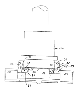
The present invention relates to a membrane unit adapted for use in a housing
of a pressure measuring unit preferably for measuring pressure in an extra-
corporal blood circuit comprising a flexible membrane and a fixing ring which
is integral with the membrane so that the membrane and the fixing ring form a
one-piece element, wherein the fixing ring has a lower flexibility than the
membrane and wherein the fixing ring comprises fixing elements for fixing the
fixing ring to the pressure meas~uring housing. The invention further relates
to a housing as well as to a pressure measuring unit.


French Abstract

La présente invention concerne une unité de membrane adaptée pour être utilisée dans un logement d~unité de mesure de pression, servant de préférence à mesurer la pression dans un circuit sanguin externe au corps comportant une membrane souple et un anneau de fixation qui est intégré avec la membrane de façon que la membrane et l~anneau de fixation forment un élément monobloc, l~anneau de fixation présentant une souplesse inférieure à celle de la membrane, et l~anneau de fixation comportant des éléments de fixation pour fixer l~anneau de fixation au logement de mesure de pression. L~invention concerne en outre un logement ainsi qu~une unité de mesure de pression.

Claims

Note: Claims are shown in the official language in which they were submitted.


- 9 -
Claims
1. Membrane unit adapted for use in a housing (10) of a pressure measuring
unit,
comprising a flexible membrane (20) and a fixing ring (30) which is integral
with the
membrane (20) so that the membrane (20) and the fixing ring (30) form a one-
piece
element, wherein the fixing ring (30) is made from a rigid material and has a
lower
flexibility than the membrane (20), which is made from elastic flexible
material, and
wherein the fixing ring (30) comprises one or more fixing elements for fixing
the fixing
ring (30) to said housing (10).
2. Membrane unit according to claim 1, wherein said pressure measuring unit is
for
measuring pressure of blood in an extra-corporeal blood circuit.
3. Membrane unit according to claim 1 or 2, characterized in that the fixing
ring (30) and
the membrane (20) are linked to each other by a connecting means.
4. Membrane unit according to claim 3, wherein said connecting means comprises

means for gluing or welding.
5. Membrane unit according to any one of claims 1 to 4, characterized in that
the fixing
ring (30) and the membrane (20) are manufactured jointly in a common process
of manufacture.
6. Membrane unit according to claim 5, characterized in that the fixing ring
(30) and the
membrane (20) are manufactured by means of two-component injection moulding.

- 10 -
7. Membrane unit according to any one of claims 1 to 6, characterized in that
the fixing
elements of the fixing ring (30) are formed as at least one projection (32),
groove or
thread.
8. Membrane unit according to claim 7, characterized in that the fixing
elements of the
fixing ring (30) are located at the outside area of the fixing ring (30)
and/or that the fixing
ring comprises a U-shaped portion, the fixing elements being located at one or
both
facing sides of the legs of the U-shaped portion.
9. Membrane unit according to any one of claims 1 to 8, characterized in that
the fixing
ring (30) is joined perpendicular to the membrane (20).
10. Membrane unit according to any one of claims 1 to 9, characterized in that
the
membrane (20) has a circumferential portion and a central portion wherein the
circumferential portion has a larger thickness than the central portion.
11. Membrane unit according to any one of claims 1 to 10, characterized in
that the
membrane (20) has a circumferentially extending sealing lip (22) for sealing a
contact
surface between the membrane (20) and said housing (10).
12. Membrane unit according to claim 11, characterized in that the sealing lip
(22)
extends into a first direction perpendicular relative to the planar area
defined by the
central portion of the membrane (20) whereas the fixing ring (30) extends
relative to this
area into the opposite direction of said first direction.
13. Membrane unit according to claim 12, wherein said sealing lip (22)
together with a
larger thickness portion in the circumferential portion of the membrane (20)
extends into
said first direction.

- 11 -
14. Membrane unit according to any one of claims 1 to 13, characterized in
that the
membrane (20) has a groove (24) on the surface facing the fixing ring (30).
15. Membrane unit according to any one of claims 11 to 14, characterized in
that the
contact surface (40) between the membrane (20) and the fixing ring (30) is not
flat.
16. Membrane unit according to claim 15, wherein said contact surface (40) is
further
provided with one or more projections (42) extending from one of the membrane
or the
fixing ring (30) which engage with one or more grooves (24) in the other of
the
membrane (20) and the fixing ring.
17. Membrane unit according to any one of claims 11 to 16, characterized in
that the
shape of the sealing lip (22) of the membrane (20) equals the shape of the
contact
surface (40) between the membrane (20) and the fixing ring (30).
18. Housing (10) of a pressure measuring unit, comprising a membrane unit
according
to any one of claims 1 to 17, an inlet (12) and an outlet (14) for a fluid the
pressure of
which is to be measured as well as a pressure measuring chamber (16) located
in fluid
communication with the inlet (12) and the outlet (14), wherein the pressure
measuring
chamber (16) has an opening (17) which is to be closed by the membrane (20)
which is
to be inserted into the housing (10), wherein the housing (10) further
comprises fixing
elements for fixing the membrane unit to the housing (10) wherein the fixing
elements
are located at one or more projections (18) extending around said opening (17)
of the
pressure measuring chamber (16).
19. Housing (10) according to claim 18, wherein said pressure measuring unit
is for
measuring pressure of blood in an extra-corporeal blood circuit.

- 12 -
20. Housing (10) according to claim 18 or 19, characterized in that the
projections (18)
extend perpendicularly relative to said opening (17) of the pressure measuring
chamber
(16).
21. Housing (10) according to any one of claims 18 to 20, characterized in
that the
fixing elements of the projection (18) are formed as groove (19), jut or
thread.
22. Housing (10) according to any one of claims 18 to 21, characterized in
that the fixing
elements are located on that side of the projection (18) which is oriented to
said opening
(17) of the pressure measuring chamber (16).
23. Pressure measuring unit comprising a membrane unit according to any one of
claims 1 to 17 and a housing (10) according to any one of claims 18 to 22,
wherein the
fixing elements of the membrane unit engage with the fixing elements of the
housing (10)
and wherein the membrane (20) of the membrane unit forms one surface of the
pressure measuring chamber (16) of the housing (10).

Description

Note: Descriptions are shown in the official language in which they were submitted.


CA 02583789 2012-10-30
-
Membrane unit, housing of a pressure measuring unit and pressure
measuring unit
Technical Field of the Invention
The present invention refers to a membrane unit adapted for use in a housing
of a
pressure measuring unit which unit is preferably adapted to measure the
pressure in
an extra-corporeal blood circuit. Such pressure measuring units are usually
referred
to as "dome" or "pressure dome". These units comprise a membrane forming one
surface of a pressure measuring chamber which membrane in use is in contact
with a
fluid and with a pressure transducer for converting pressures and pressure
changes
of the fluid into electrical signals.
Background
A pressure measuring unit comprising a membrane and a housing is known from US

patent 5,614,677. The pressure measuring unit disclosed in this document
comprises a housing comprising a pressure measuring chamber which is in fluid
communication with an inlet and outlet of the housing. One surface of the
pressure
measuring chamber is formed by a membrane which is fixed to the housing by
means of a tension ring inserted in a groove on the upper surface of the
housing.
The tension ring is fixed in its position by aid of a guide of the transducer
which is
abutting the upper surface of the housing.

CA 02583789 2012-10-30
-2-
Prior art document W099/37983 also discloses a pressure measuring unit
comprising
a housing with a pressure measuring chamber one surface of which is formed by
a
membrane. The membrane comprises a circumferentially extending bead which is
located on the side of the membrane facing the measuring chamber and which is
pressed into a groove of the housing. A similar arrangement is known from U.S.

patent application US 2004/0050168 Al.
The pressure measuring units described in the prior art are disadvantageous as
the
mounting of the membrane to the housing is cumbersome or has to be established
by
the membrane itself which is made of soft material.
Summary of the Invention
Accordingly, it is the object of the present invention to provide a membrane
which
can easily be fixed in a pressure measuring housing and at the same time
exhibits
good pressure transmitting and sealing properties.
According to the invention a membrane unit is provided adapted to be inserted
into a
housing of a pressure measuring unit preferably used for measuring pressure in
an
extracorporeal blood circuit which membrane unit comprises a flexible membrane

and a fixing ring which is integral with the membrane so that the membrane and
the
fixing ring form a one-piece element, wherein the fixing ring has a lower
flexibility than
the membrane and wherein the fixing ring comprises fixing elements for fixing
the
fixing ring to the housing. Accordingly, the membrane is part of a one-piece
element
composed of the membrane and a fixing ring having a lower flexibility than the
mem-
brane. The invention ensures that the membrane is fixed reliably in the
housing and
thus reveals a good pressure transmitting property to a transducer facing the
mem-
brane on the other side than the fluid. Further a good sealing property of the
mem-
brane is obtained. A further advantage of the membrane unit according to the
in-
vention is that it can be easily mounted into the housing by engaging the
fixing ele-
ments of the ring with the housing.

CA 02583789 2007-04-16
WO 2006/053673 PCT/EP2005/012042
- 3 -
The fixing ring as well as the membrane can be connected to each other by
means
of a suitable connection technique for example by means of glueing or welding.
Alternatively, the fixing ring and the membrane can form a joint element which
is
manufactured in a common process of manufacture. One example of such a proc-
ess is two-component injection moulding. Accordingly, the membrane unit can be

manufactured as one part or can also be manufactured as two elements which are

linked to each other in a second step.
In a further embodiment of the invention the fixing elements of the fixing
ring are
formed as at least one projection, groove or thread. Alternative fixing
elements are
also conceivable.
The fixing elements of the fixing ring are located in a further embodiment of
the in-
vention at the outside portion of the fixing ring. Further the fixing ring may
comprise
a U-shaped portion and the fixing elements are located at one or both facing
sides
of the legs of the U-shaped portion.
The fixing ring may be arranged in a standing upright position on the
membrane,
preferably on the circumferential portion of the membrane. Preferably the ring
ex-
tends perpendicularly relative to the membrane.
Furthermore, the circumferential portion of the membrane may have a larger
thick-
ness than the central portion of the membrane to improve the sealing
properties.
In a further embodiment of the invention the membrane has a circumferential ex-

tending sealing lip for sealing the contact surface between the membrane and
the
housing. The sealing lip is fixed in the correct position by means of the
fixing ring
which itself is fixed at the housing.
In a further embodiment the sealing lip, in particular together with the
possible lar-
ger thickness portion in the circumferential portion of the membrane, extends
into a

CA 02583789 2012-10-30
-4-
first direction perpendicular relative to the planar area defined by the
central portion of
the membrane whereas the ring extends relative to this area into the opposite
direction of said first direction. In this embodiment, during use the fluid
whose pres-
sure is to be determined contacts the central portion of the membrane from the
side of
the first direction whereas the pressure transducer contacts the membrane from
the
opposite site.
In another embodiment of the invention the membrane has a groove on the
surface
facing the fixing ring for receiving a portion of the fixing ring.
The contact surface between the membrane and the fixing ring may be provided
with one or more projections extending from one of the membrane or the fixing
ring
which engage with a groove in the other of the membrane and the fixing ring.
The
contact surface for example can be formed by a groove in the surface of the
mem-
brane facing the fixing ring with the fixing ring being accommodated in this
groove
with its portion abutting the membrane.
In a further embodiment of the invention the shape of the sealing lip of the
mem-
brane equals the shape of the contact surface between the membrane and the
fixing
ring.
The present invention further refers to a housing of a pressure measuring unit
which
housing is adapted to receive a membrane unit, the housing comprising an inlet
and
an outlet for a fluid, the pressure of which is to be measured as well as a
pressure
measuring chamber being in fluid communication with the inlet and the outlet,
wherein the pressure measuring chamber has an opening which is to be closed by
a
membrane which is to be inserted into the housing, wherein the housing further

comprises fixing elements for fixing a membrane unit to the housing wherein
the
fixing elements are located at one or more projections extending around said
opening
of the pressure measuring chamber.

CA 02583789 2012-10-30
-5-
The projection may extend perpendicularly relative to that surface of the
pressure
measuring chamber which is formed by a membrane, i.e. perpendicularly relative
to
the opening of the pressure measuring chamber which is to be closed by the mem-

brane.
The projection may extend circumferentially around the longitudinal axis of
the
pressure measuring chamber which axis is perpendicular to said opening of the
pressure measuring chamber. In a preferred embodiment the projection is
located
concentrically with the longitudinal axis of the pressure measuring chamber.
The fixing elements of the projection of the housing may be formed as groove,
jut or
thread.
In a further embodiment of the invention the fixing elements are located on
that side of
the projection which is oriented to said opening of the pressure measuring
chamber.
The fixing elements may extend perpendicularly to the projection.
The invention is further directed to a pressure measuring unit comprising a
mem-
brane unit and a housing, wherein the fixing elements of the membrane unit
engage
with the fixing elements of the housing and wherein the membrane of the
membrane
unit forms one surface of the pressure measuring chamber of the housing.
Brief Description of the Drawings
Further details and advantages of the invention become apparent from an embodi-

ment which is now described as an example by aid of the drawings:
Figure 1 shows the pressure measuring unit according to the invention with a
pressure transducer inserted therein,
Figure 2,
Figure 3 show in detail the fixing ring and the membrane in different
embodiments
and

CA 02583789 2012-10-30
-6-
Figure 4 shows the fixing ring and the membrane after and before assembly
according to figure 3.
Detailed Description
Figure 1 shows the housing 10 comprising an inlet 12 and an outlet 14 for
connection
to an extra-corporeal blood circuit of a dialysis apparatus. Between the inlet
12 and
the outlet 14 is located the pressure measuring chamber 16 which is in fluid
communication with the inlet 12 and the outlet 14. In this embodiment the
pressure
chamber 16 has a circular cross section when viewed from the top. The pressure

measuring chamber 16 is terminated at the top by the lower surface of a
circular
membrane 20 which closes the upper opening 17 of the pressure measuring cham-
ber 16. At the edge of the membrane 20 there is a sealing lip 22 at the lower
surface
of the membrane 20 facing toward the housing 10 and a groove 24 on the upper
surface of the membrane 20 facing a fixing ring 30. The interior walls of the
pressure
measuring chamber 16 below the membrane 20 may have any shape suitable for the

required purpose (e.g. rounded edges for blood compatibility, not shown in
detail).
The membrane 20 and the fixing ring 30 form a one-piece element which is con-
nected after manufacture of both parts or which is manufactured in a single
process,
for example by injection moulding.
The fixing ring 30 is made from a rigid material for guaranteeing the position
of the
soft sealing membrane 20 after assembling. The membrane 20 is made from
elastic
flexible material (for example thermoplastic elastomer, rubber) for sealing
purposes
as well as for transmitting the pressure/pressure changes to the transducer
100
abutting the upper surface of the membrane 20.
The membrane 20 and the fixing ring 30 are in permanent contact with each
other
and the contact surface 40 between both parts is not flat for providing more
surface
for adhesion between the rigid material of the fixing ring 30 and the soft
material of
the membrane 20. In the present embodiment the contact surface 40 comprises a

CA 02583789 2007-04-16
WO 2006/053673 PCT/EP2005/012042
- 7 -
=
projection 42 of the fixing ring 30 which engages with a groove 24 on the
upper sur-
face of the membrane 20 facing the fixing ring 30.
As further shown in figure 1 the fixing ring 30 at its outer surface comprises
a radial
projection 32 which is inserted into a corresponding groove 19 on the inside
of a
cylindrical projection 18 of the housing 10. The projection 18 extends
perpendicu-
larly to and circumferentially around the membrane 20. At its inner surface
the pro-
jection 18 comprises the circumferentially extending groove 19 in which as men-

tioned above the also circumferentially extending projection 32 of the fixing
ring 30
is inserted. The projection 18 and the fixing ring 30 are arranged vertically,
i. e. per-
pendicularly to the membrane 20.
The membrane unit consisting of membrane 20 and fixing ring 30 can easily be
in-
serted into the housing 10. Due to the presence of a rigid material in form of
the
fixing ring 30 the desired position of the fixing ring 30 and of the membrane
20 is
reliably established so that a good sealing property as well as a good
pressure
transmitting property of the membrane 20 are obtained. The membrane unit is
eas-
ily connected to the housing 10 by pushing the membrane unit from the top
until the
projection 32 snaps into the groove 19. As both the fixing ring 30 and the
projection
18 are made of sufficiently rigid materials a firm connection is achieved. At
the
same time the membrane 20 touches the rim 25 of an opening 17 in the housing
10
that is to be closed by the membrane 20. Using appropriate sizes this contact
can
be used to apply a certain amount of tension to the membrane 20 upon fixing
the
ring 30 to the housing 10. This tension may be advantageous for the pressure
transmitting properties for fluid pressures both below and above ambient
pressure.
As the circumferential portion of the membrane 20 comprises a larger thickness

portion 26 that is positioned in a groove 27 surrounding the rim 25 of the
housing 10
the membrane 20 is well sealed by this circumferential portion against the
housing
10. The sealing is further supported by the sealing lip 22 that is pressed by
the fix-
ing ring 30 into a complementary structure in the groove 27.

CA 02583789 2007-04-16
WO 2006/053673 PCT/EP2005/012042
- 8 -
As shown in figure 1 the fixing ring 30 is joined perpendicularly to the
circumferen-
tial portion of the membrane 20.
In the shown embodiment the two parts are joined in a direction being opposite
to
the direction the larger thickness portion 26 extends relative to the planar
area de-
fined by the central portion of the membrane 20.
Figures 2 and 3 show two different embodiments of the invention in which the
con-
tact surface 40 between the membrane 20 and the fixing ring 30 differs.
According
to figure 2 the contact surface 40 differs in its shape from the shape of the
sealing
lip 22 and in the embodiment of figure 3 the contact surface 40 as well as the
seal-
ing lip 22 have a similar or identical shape.
As an alternative embodiment the fixing ring 30 may also have an inverted U-
shaped upper portion so that it can be pushed over the projection 18 of the
housing
10. In this case fixing elements may be provided on one or both of the legs of
the U-
shaped portion of the fixing ring 30.
In a further embodiment the fixing ring 30 and the projection 18 may have a
thread
or other suitable fixing elements.
Figure 4 shows different views of the membrane unit composed of membrane 20
and fixing ring 30. The embodiment of figure 4 corresponds to that shown in
figure
3. As may be gathered from figure 4 the membrane unit is composed of two parts

which are linked to each other after manufacture thereof for example by
glueing or
welding. After the assembly the complete unit consisting of membrane 20 and
fixing
ring 30 is inserted into the housing 10 shown in figure 1.

Representative Drawing
A single figure which represents the drawing illustrating the invention.
Administrative Status

For a clearer understanding of the status of the application/patent presented on this page, the site Disclaimer , as well as the definitions for Patent , Administrative Status , Maintenance Fee  and Payment History  should be consulted.

Administrative Status

Title Date
Forecasted Issue Date 2013-09-03
(86) PCT Filing Date 2005-11-10
(87) PCT Publication Date 2006-05-26
(85) National Entry 2007-04-16
Examination Requested 2010-08-12
(45) Issued 2013-09-03

Abandonment History

There is no abandonment history.

Maintenance Fee

Last Payment of $473.65 was received on 2023-10-19


 Upcoming maintenance fee amounts

Description Date Amount
Next Payment if standard fee 2024-11-12 $624.00
Next Payment if small entity fee 2024-11-12 $253.00

Note : If the full payment has not been received on or before the date indicated, a further fee may be required which may be one of the following

  • the reinstatement fee;
  • the late payment fee; or
  • additional fee to reverse deemed expiry.

Patent fees are adjusted on the 1st of January every year. The amounts above are the current amounts if received by December 31 of the current year.
Please refer to the CIPO Patent Fees web page to see all current fee amounts.

Payment History

Fee Type Anniversary Year Due Date Amount Paid Paid Date
Application Fee $400.00 2007-04-16
Maintenance Fee - Application - New Act 2 2007-11-13 $100.00 2007-04-16
Maintenance Fee - Application - New Act 3 2008-11-10 $100.00 2008-10-30
Maintenance Fee - Application - New Act 4 2009-11-10 $100.00 2009-10-15
Request for Examination $800.00 2010-08-12
Maintenance Fee - Application - New Act 5 2010-11-10 $200.00 2010-10-18
Maintenance Fee - Application - New Act 6 2011-11-10 $200.00 2011-10-17
Maintenance Fee - Application - New Act 7 2012-11-13 $200.00 2012-10-30
Registration of a document - section 124 $100.00 2013-06-20
Final Fee $300.00 2013-06-20
Maintenance Fee - Patent - New Act 8 2013-11-12 $200.00 2013-10-24
Maintenance Fee - Patent - New Act 9 2014-11-10 $200.00 2014-10-27
Maintenance Fee - Patent - New Act 10 2015-11-10 $250.00 2015-10-28
Maintenance Fee - Patent - New Act 11 2016-11-10 $250.00 2016-10-20
Maintenance Fee - Patent - New Act 12 2017-11-10 $250.00 2017-10-19
Maintenance Fee - Patent - New Act 13 2018-11-13 $250.00 2018-10-23
Maintenance Fee - Patent - New Act 14 2019-11-12 $250.00 2019-10-22
Maintenance Fee - Patent - New Act 15 2020-11-10 $450.00 2020-10-21
Maintenance Fee - Patent - New Act 16 2021-11-10 $459.00 2021-10-20
Maintenance Fee - Patent - New Act 17 2022-11-10 $458.08 2022-10-24
Maintenance Fee - Patent - New Act 18 2023-11-10 $473.65 2023-10-19
Owners on Record

Note: Records showing the ownership history in alphabetical order.

Current Owners on Record
FRESENIUS MEDICAL CARE DEUTSCHLAND GMBH
Past Owners on Record
CARONNA, MARCO
REITER, REINHOLD
Past Owners that do not appear in the "Owners on Record" listing will appear in other documentation within the application.
Documents

To view selected files, please enter reCAPTCHA code :


To view images, click a link in the Document Description column. To download the documents, select one or more checkboxes in the first column and then click the "Download Selected in PDF format (Zip Archive)" or the "Download Selected as Single PDF" button.

List of published and non-published patent-specific documents on the CPD .

If you have any difficulty accessing content, you can call the Client Service Centre at 1-866-997-1936 or send them an e-mail at CIPO Client Service Centre.


Document
Description 
Date
(yyyy-mm-dd) 
Number of pages   Size of Image (KB) 
Abstract 2007-04-16 2 66
Claims 2007-04-16 4 123
Drawings 2007-04-16 3 23
Description 2007-04-16 8 339
Representative Drawing 2007-06-19 1 5
Cover Page 2007-06-20 1 37
Description 2012-10-30 8 327
Claims 2012-10-30 4 131
Cover Page 2013-08-06 2 41
Assignment 2007-07-06 4 104
Correspondence 2007-07-06 2 57
PCT 2007-04-16 4 209
Assignment 2007-04-16 4 118
Correspondence 2007-06-20 1 20
Prosecution-Amendment 2010-08-12 1 52
Assignment 2013-06-20 5 117
Prosecution-Amendment 2012-05-28 3 145
Prosecution-Amendment 2012-10-30 17 612
Correspondence 2013-06-20 2 55