Note: Descriptions are shown in the official language in which they were submitted.
CA 02583902 2007-04-11
WO 2006/049842 PCT/US2005/036937
1
VALVE
CROSS-REFERENCE TO RELATED APPLICATIONS
[0001] This patent application claims the benefit of U.S. Provisional Patent
Application
No. 60/622,610, filed October 28, 2004, which is incorporated by reference.
BACKGROUND OF THE INVENTION
[0002] A variety of in-line devices are used to control fluid flow. Typically,
the device
comprises a housing with a valve disposed therein, wherein the valve includes
a frangible
portion that is broken when it is desired to allow fluid flow through the
device.
[0003] These devices have suffered from a number of drawbacks. For example,
the
frangible portion may fail to break off completely, or, once broken off, can
become lodged
in an undesired location and restrict fluid flow. The frangible portion can
adversely affect
the fluid, e.g., if the fluid is a biological fluid, red blood cells
contacting the portion can
become hemolyzed and/or platelets contacting the portion can become activated.
Alternatively, or additionally, red blood cells and/or platelets can aggregate
upon contacting
the portion. Some devices require the use of a tool to facilitate breaking the
frangible
portion. Additionally, or alternatively, the valves may have to be oriented in
a specified
direction (e.g., so that the frangible portion is arranged in the downstream
direction) to be
operated to allow fluid flow, thus requiring careful assembly of the devices.
[0004] The present invention provides for ameliorating at least some of the
disadvantages of the prior art. These and other advantages of the present
invention will be
apparent from the description as set forth below.
BRIEF SUMMARY OF THE INVENTION
[0005] In an embodiment of the invention a valve is provided comprising a
housing
comprising a first section and a second section; the first section comprising
at least one
inlet; the second section comprising at least one outlet; wherein the first
section is rotatably
engaged with the second section, and, while the sections are engaged, one
section can be
rotated with respect to the other section from a first position wherein fluid
flow through the
housing is prevented to a second position allowing fluid flow through the
housing.
[0006] Another embodiment of a valve according to the invention comprises a
housing
comprising a first section and a second section; the first section comprising
at least one inlet
and at least one inlet fluid flow channel; the second section comprising at
least one outlet
and at least one outlet fluid flow channel; wherein the first section is
rotatably engaged with
CA 02583902 2007-04-11
WO 2006/049842 PCT/US2005/036937
2
the second section, and, while the sections are engaged, the first section is
rotatable with
respect to the second section from a first position that prevents fluid flow
through the
housing, to a second position that allows fluid flow through the housing.
[0007] In preferred embodiments, the valve includes a gasket interposed
between the
sections, wherein the gasket includes at least one opening that allows fluid
flow
therethrough when a section is rotated from the first position to the second
position.
[0008] Alternatively, or additionally, in some embodiments the valve includes
at least
two inlets and/or at least two outlets.
[0009] In another embodiment, the valve comprises a housing comprising a first
section
and a second section; the first section comprising a first inlet and a second
inlet, the second
section comprising an outlet; optionally, a gasket interposed between the
first section and
the second section, the gasket including at least one opening for allowing
fluid flow
therethrough, wherein the first section is rotatably engaged with the second
section, and,
while the sections are engaged, one section can be rotated with respect to the
other section
from a first position wherein fluid flow through the housing is prevented to a
second
position allowing fluid flow through the housing. In a more preferred
embodiment, the first
section can be rotated to a plurality of second positions, the positions
allowing fluid flow
from the first inlet and through the outlet, fluid flow from the second inlet
and through the
outlet and/or allowing fluid flow from the first and second inlets and through
the outlet.
[0010] In another embodiment, the invention provides a fluid processing device
comprising at least one conduit communicating with a valve, the valve
comprising a housing
comprising a first section and a second section; the first section comprising
at least one
inlet; the second section comprising at least one outlet; wherein the first
section is rotatably
engaged with the second section, and, while the sections are engaged, one
section can be
rotated with respect to the other section from a first position wherein fluid
flow through the
housing is prevented to a second position allowing fluid flow through the
housing. In some
embodiments, the device comprises a first conduit connected to the first
section of the
housing, and a second conduit connected to the second section of the housing.
In other
embodiments, the device comprises a first conduit connected to the first
section of the
housing, and a fluid processing container having at least two fluid flow
ports, wherein one
fluid flow port of the fluid processing container connected to the second
section of the
housing.
[0011] In yet another embodiment, a fluid processing system is provided,
comprising a
fluid processing device as described above, and at least one fluid processing
container
comprising a flexible bag including at least two fluid flow ports, wherein the
container is in
fluid communication with the valve.
CA 02583902 2007-04-11
WO 2006/049842 PCT/US2005/036937
3
BRIEF DESCRIPTION OF THE SEVERAL VIEWS OF THE DRAWING(S)
[0012] Figure 1 is a cross-sectional view of an embodiment of a valve
according to the
present invention comprising first and second housing sections and a gasket.
Figure 1 a
shows an exploded view, Figure lb shows an assembled view, wherein the first
housing
section is in a first position with respect to the second housing section,
which prevents flow
through the valve, and Figure lc shows a top view of an embodiment of a gasket
in the
valve.
[0013] Figure 2 shows a cross-sectional view of the embodiment of the valve
shown in
Figure 1, wherein the first housing section is in a second position with
respect to the second
housing section, which allows flow through the valve.
[0014] Figure 3 shows a cross-sectional view of the second section of the
valve shown
in Figure 1, including a gasket sealed to the second section.
[0015] Figure 4 shows a top view of the second section of the valve shown in
Figure la,
also showing grooves for use in sealing the gasket to the second section and
showing part of
a locking arrangement.
[0016] Figure 5 shows a top view of the second section of the valve shown in
Figure 4,
also showing the gasket.
[0017] Figure 6 shows a side view of the second section of the valve shown in
Figure
1 a, showing part of a locking arrangement.
[0018] Figure 7 shows a bottom view of the first section of the valve shown in
Figure
1 a.
[0019] Figure 8 (Figures 8a-8e) shows another embodiment of a gasket for use
in an
embodiment of a valve according to the invention. Figures 8b-8e also show a
portion of the
first section of the valve, illustrating adjusting the flow of fluid through
the valve.
[0020] Figure 9 (Figures 9a-9e) shows various views of another embodiment of a
valve
according to the present invention comprising first and second housing
sections and a
gasket, wherein the first section includes first arid second inlets, and the
second section
includes a single outlet. Figure 9a shows an exploded cross-sectional view,
Figure 9b
shows, in an exploded view, the gasket and the gasket contacting surfaces of
the first and
second sections, Figures 9c, 9d, and 9e show assembled side, front, and rear
cross-sectional
views, respectively. Figure 9d shows the valve wherein the first section is in
a second
position providing fluid flow paths between the first and second inlets and
the outlet.
Figure 9e shows the valve wherein the first section is in a first position
wherein the fluid
flow paths are closed between the first and second inlets and the outlet.
CA 02583902 2007-04-11
WO 2006/049842 PCT/US2005/036937
4
[0021] Figure 10 (Figures l0a-lOd) shows various views of the gasket and a
bottom
portion of the first housing section of Figure 9 illustrating allowing and
preventing fluid
flow through the valve between the first inlet and the outlet and/or between
the second inlet
and the outlet.
[0022] Figure 11 shows an embodiment of a fluid processing device, including
the
assembled valve shown in Figure lb, with first and second conduits connected
to the first
and second sections of the housing, respectively.
[0023] Figure 12 (Figures 12a-12b) shows various views of another embodiment
of a
fluid processing device, including the assembled valve shown in Figure 9, with
separate
conduits connected to the first and second inlets of the first section of the
housing, and an
additional conduit connected to the outlet of the second section of the
housing.
[0024] Figure 13 shows various views of another embodiment of a valve
according to
the present invention comprising first and second housing sections and a
gasket, wherein the
first section includes first and second inlets, and the second section
includes a single outlet,
and wherein the valve is arranged such that the proportions of two different
fluids passing
through the valve can be adjusted. Figure 13a shows a top view, Figure 13b
shows a
cross-sectional view along line A-A, Figure 13c shows a cross-sectional view
along line B-
B. Figures 13d-h show the gasket and the bottom portion of the first section
of the valve,
illustrating allowing and preventing flow through the valve between the first
inlet and the
outlet and/or between the second inlet and the outlet, as well as
incrementally uncovering
the ends of the fluid flow channels to change the flow of fluids through the
valve.
[0025] Figure 14 shows a cross-sectional view an embodiment of an assembled
valve
according to the invention without a gasket between the first and second
housing sections.
[0026] Figure 15 (Figures 15a-15b) shows cross-sectional views of another
embodiment
of an assembled valve according to the present invention comprising first and
second
housing sections, wherein the first section includes first and second inlets,
and the second
section includes a single outlet, and wherein the valve does not include a
gasket between the
first and second housing sections.
[0027] Figure 16 is a cross-sectional view of another embodiment of an
assembled
valve according to the present invention, wherein the second section has been
swaged for
engagement with the first section.
[0028] Figure 17 is a cross-sectional view of another embodiment of an
assembled
valve according to the present invention, wherein the sections have been
engaged using an
ultrasonic seal. Figure 17a shows an embodiment without a gasket, and Figure
17b shows
an embodiment with a gasket.
CA 02583902 2007-04-11
WO 2006/049842 PCT/US2005/036937
[0029] Figure 18 shows an embodiment of a fluid processing device, including
the
assembled valve shown in Figure lb, with a first conduit connected to the
first section of the
housing, and a fluid processing container, wherein a fluid flow port of the
fluid processing
container is connected to the second section of the housing.
[0030] Figure 19 shows an embodiment of a biological fluid processing system
including the biological fluid processing devices illustrated in Figures 11
and 18.
[0031] Figure 20 shows an embodiment of a biological fluid processing system
including the biological fluid processing devices illustrated in Figure 12.
[0032] Figure 21 shows an embodiment of a fluid processing device comprising a
valve
and a container, wherein the valve has indicia showing the direction of
rotation of a housing
section and indicia showing reference positions for different flow rates
through the valve,
allowing a user to adjust flow rates as desired.
[0033] Figure 22 shows another embodiment of a system, comprising two valves
as
shown in Figure 9, a vent communicating with each valve, a filter interposed
between the
valves, an upstream container, and a downstream container. Figure 22 also
shows various
views of the gasket and a bottom portion of the first housing section of each
valve
illustrating allowing and preventing fluid flow through the valve between at
least one inlet
and/or at least one outlet.
DETAILED DESCRIPTION OF THE INVENTION
[0034] In an embodiment, the invention provides a valve comprising a housing
comprising a first section and a second section; the first section comprising
at least one
inlet; the second section comprising at least one outlet; wherein the first
section is rotatably
engaged with the second section, and, while the sections are engaged, one
section can be
rotated with respect to the other section from a first position wherein fluid
flow through the
housing is prevented to a second position allowing fluid flow through the
housing. In one
embodiment, the first section is rotatable with respect to the second section
from a first
position that prevents fluid flow through the housing, to a second position
that allows fluid
flow through the housing.
[0035] Another embodiment of a valve according to the invention comprises a
housing
comprising a first section and a second section; the first section comprising
at least one inlet
and at least one inlet fluid flow channel; the second section comprising at
least one outlet
and at least one outlet fluid flow channel; wherein the first section is
rotatably engaged with
the second section, and, while the sections are engaged, the first section is
rotatable with
respect to the second section from a first position that prevents fluid flow
through the
housing, to a second position that allows fluid flow through the housing.
CA 02583902 2007-04-11
WO 2006/049842 PCT/US2005/036937
6
[0036] In a preferred embodiment, the valve includes a gasket interposed
between the
sections, wherein the gasket includes at least one opening that allows fluid
flow
therethrough when a section is rotated from the first position to the second
position.
[0037] Alternatively, or additionally, in some embodiments the valve includes
at least
two inlets and/or at least two outlets.
[0038] In another embodiment, the valve comprises a housing comprising a first
section
and a second section; the first section comprising a first inlet and a second
inlet, the second
section comprising an outlet; an optional gasket interposed between the first
section and the
second section, the gasket including at least one opening for allowing fluid
flow
therethrough, wherein the first section is rotatably engaged with the second
section, and,
while the sections are engaged, one section can be rotated with respect to the
other section
from a first position wherein fluid flow through the housing is prevented to a
second
position allowing fluid flow through the housing. In a more preferred
embodiment, the first
section can be rotated to a plurality of second positions, the positions
allowing fluid flow
from the first inlet and through the outlet, fluid flow from the second inlet
and through the
outlet and/or allowing fluid flow from the first and second inlets and through
the outlet. In
some embodiments, the proportions of two fluids passing through the valve can
be adjusted
as desired.
[0039] A fluid processing device according to another embodiment of the
invention
comprises an embodiment of the valve as described above, at least a first
conduit connected to
the first section of the housing, and a flexible container including two or
more fluid flow ports,
wherein one of the fluid flow ports is connected to the second section of the
housing.
[0040] In an embodiment, the invention provides a fluid processing device
comprising an
embodiment of the valve as described above, at least one first conduit
connected to the first
section of the housing, and at least one second conduit connected to the
second section of the
housing. In some embodiments, the fluid processing device has at least two
first conduits
connected to the first section of the housing, and at least one second conduit
connected to the
second section of the housing, or at least one first conduit connected to the
first section of the
housing, and at least two second conduits connected to the second section of
the housing.
[0041] An embodiment of a biological fluid processing system is also provided,
comprising a fluid processing device including at least one first conduit and
at least one
second conduit as described above, and a first biological fluid processing
container
comprising a flexible bag including at least two fluid flow ports, wherein one
of the conduits is
in fluid communication with one of the fluid flow ports. The biological fluid
processing
system can include at least one additional container, e.g., a flexible bag
including at least one
fluid flow port, wherein the additional (e.g., second) bag is in fluid
communication with the
CA 02583902 2007-04-11
WO 2006/049842 PCT/US2005/036937
7
other conduit. Alternatively, or additionally, embodiments of the biological
fluid processing
system can include additional containers, e.g., wherein the containers are
downstream of, and
in fluid communication with, the first or second bags.
[0042] In yet another embodiment, a biological fluid processing system is
provided,
comprising a fluid processing device as described above, and at least one
additional
biological fluid processing container comprising a flexible bag including at
least two fluid flow
ports.
[0043] Embodiments of fluid processing devices and/or systems can include two
or more
conduits, two or more bags, and/or two or more valves.
[0044] Advantageously, the valve can be operated to allow fluid flow when
desired
without breaking a frangible portion, and thus, there is no frangible portion
in the fluid flow
path that could adversely affect fluid flow and/or adversely affect the
biological fluid
components in the fluid being processed in accordance with embodiments of the
invention.
The valve can be operated without special tools. Also advantageously, the
valve includes
smooth rounded surfaces and edges where the biological fluid contacts the
valve, further
minimizing the potential to stress the biological fluid components. In
accordance with
another advantage, the valve can be oriented in any direction with respect to
fluid flow, e.g.,
either end can be "upstream" or "downstream."
[0045] Yet another advantage is that, if desired, the valve can be operated
(e.g., in a
biological fluid processing system) such that fluid flow can be started and/or
stopped
without clamping and unclamping one or more conduits communicating with the
valve.
Avoiding clamping can be advantageous in that clamping can damage one or more
components in the fluid present in the conduit(s) and/or clamping and
unclamping can be
labor intensive. This can be especially desirable in some embodiments wherein
the valve
includes more than one inlet and/or more than one outlet, as the valve can be
operated (e.g.,
as a"Y" or "T" connector) to provide combined or separated fluid flow paths,
without
clamping and unclamping the conduit(s) communicating with the valve.
[0046] Avoiding clamping can also be advantageous in that clamped conduits can
take a
"set," e.g., wherein the conduit does not return to its initial full open flow
position and/or
the clamp (e.g., a roller clamp) can "creep" such that the clamping force
changes, allowing
changes in the flow rate.
[0047] In accordance with another advantage, the flow rate through the valve
can be
readily adjusted and/or controlled, if desired.
[0048] In accordance with the invention, one or more fluid flow paths, e.g.,
one or more
liquid flow paths, can be established through the engaged sections once one of
the sections
has been rotated, allowing fluid(s) to flow through the valve, wherein the
fluid flow path(s)
CA 02583902 2007-04-11
WO 2006/049842 PCT/US2005/036937
8
is/are isolated from the ambient environment and from contaminants present in
the ambient
environment. In some embodiments, the fluid flow path(s) can be established
while
maintaining a sterile fluid pathway, making the invention suitable for use in
closed systems.
100491 Embodiments of the invention are suitable for use with a variety of
fluids,
preferably, biological fluids.
[0050] Biological Fluid. A biological fluid includes any treated or untreated
fluid
associated with living organisms, particularly blood, including whole blood,
wann or cold
blood, and stored or fresh blood; treated blood, such as blood diluted with at
least one
physiological solution, including but not limited to saline, nutrient, and/or
anticoagulant
solutions; blood components, such as platelet concentrate (PC), platelet-rich
plasma (PRP),
platelet-poor plasma (PPP), platelet-free plasma, plasma, fresh frozen plasma
(FFP),
components obtained from plasma, packed red cells (PRC), transition zone
material or buffy
coat (BC); blood products derived from blood or a blood component or derived
from bone
marrow; stem cells; red cells separated from plasma and resuspended in
physiological fluid
or a cryoprotective fluid; and platelets separated from plasma and resuspended
in
physiological fluid or a cryoprotective fluid. The biological fluid may have
been treated to
remove some of the leukocytes before being processed according to the
invention. As used
herein, blood product or biological fluid refers to the components described
above, and to
similar blood products or biological fluids obtained by other means and with
similar
properties.
[0051] A "unit" is the quantity of biological fluid from a donor or derived
from one unit
of whole blood. It may also refer to the quantity drawn during a single
donation. Typically,
the volume of a unit varies, the amount differing from patient to patient and
from donation
to donation. Multiple units of some blood components, particularly platelets
and buffy coat,
may be pooled or combined, typically by combining four or more units.
[0052] As used herein, the term "closed" refers to a system that allows the
collection
and processing (and, if desired, the manipulation, e.g., separation of
portions, separation
into components, filtration, storage, and preservation) of biological fluid,
e.g., donor blood,
blood samples, and/or blood components, without the need to compromise the
sterile
integrity of the system. A closed system can be as originally made, or result
from the
connection of system components using what are known as "sterile docking"
devices.
Illustrative sterile docking devices are disclosed in U.S. Patent Nos.
4,507,119, 4,737,214,
and 4,913,756.
[0053] Each of the components of the invention will now be described in more
detail
below, wherein like components have like reference numbers.
CA 02583902 2007-04-11
WO 2006/049842 PCT/US2005/036937
9
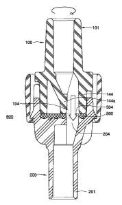
[00541 Figure 1 a shows an exploded cross-sectional view of a valve 600
according to an
embodiment of the invention, comprising a housing 400 comprising a first
section 100 and a
second section 200, wherein, once assembled as shown in Figures lb and 2, the
sections are
rotatably engaged together.
[0055] The housing and sections can be fabricated from any suitable impervious
material or materials (e.g., rigid, semi-rigid, and/or elastic impervious
material(s)),
including any impervious thermoplastic material, which is compatible with the
fluid,
preferably, biological fluid, being processed. The housing and sections are
preferably
formed from a polymeric material, e.g., molded from a polymeric material such
as an
acrylic, polypropylene, polystyrene, or a polycarbonated resin. The housing
and sections
can be formed from a plurality of materials (e.g., one section can be formed
from a different
material or combinations of materials than another section). For example, one
section can
be formed from a rigid material, and another section can be formed from a semi-
rigid or
elastic material. Alternatively, or additionally, a section can have, for
example, a portion
formed from a rigid material, and another portion formed from a semi-rigid or
elastic
material.
[0056] In some embodiments, the housing and sections (or portions thereof) are
formed
from a transparent or translucent polymer, e.g., to allow observation of the
passage of the
fluid through the housing. Typically, the first and second sections are each
single-piece
sections, although in some embodiments, at least one section comprises two or
more pieces.
[0057] In the embodiment shown in Figures la and lb, the first section 100
includes an
inlet 101, and a channel or aperture 102 (having open ends 103 and 104, the
channel being
formed by side wall 112), and second section 200 includes an outlet 201, and a
channel or
aperture 202 (having open ends 203 and 204, the channel being formed by side
wa11212),
and a gasket 500 including at least one cut-out or opening 504 is interposed
between the
channels 102 and 202. In this illustrated embodiment, the open ends in each
channel are
offset from one another, i.e., open end 103 is offset from open end 104, and
open end 203 is
offset from open end 204.
[0058] One section can be rotated independently of the other section while the
sections
remained engaged, preferably one section can be rotated with respect to the
other section
(e.g., one section rotates while the other remains stationary) from a first
position wherein
fluid flow through the housing is prevented, to at least a second position
wherein fluid flow
through the housing is allowed (e.g., using Figure 2 for reference, wherein
the three
openings 104, 504, and 204 are at least partially aligned to allow fluid flow
therethrough).
[0059] For directional orientation in the following discussion, each section
has a
proximal end, nearest the opposing section, and a distal end, furthest from
the opposing
CA 02583902 2007-04-11
WO 2006/049842 PCT/US2005/036937
section. Also, since the exemplary sections 100, 200 in the Figures comprise
elongated
bodies, the term axial denotes disposition along their axes.
[0060] In one embodiment, e.g., as shown in Figures la and lb (cross-sectional
view)
and Figure 7 (bottom view), the valve 600 comprises a housing 400 comprising
first section
100 and second section 200, wherein the first section 100 comprises a first
inlet 101 and a
sidewall 112 providing a channel 102 having open ends 103 and 104. The first
section also
comprises a flange 142 (the flange typically assuming a radially extending
annular plan
form) and a sidewall 144 extending from the flange. In the illustrated
embodiment, an
additional side wall 144a also extends from the flange 142. A portion of
sidewalls 144 and
sidewall 144a is continuous with channel sidewall 112, and provides channel
open end 104.
The opening 104 can have a variety of shapes, and in one embodiment, as
described below,
the opening is generally "D" shaped.
[00611 The sidewall 144 includes a proximal end surface 143 (preferably,
wherein the
surface is rounded) facing the second section 200, and, in the this
illustrated embodiment,
which includes an additional sidewall 144a, the sidewall 144a includes a
proximal end
surface 143a (preferably, wherein the surface is rounded) and there is a space
149 between
additional sidewall 144a and the portion of the sidewall 144 not providing
channel sidewall
112. In another illustrative embodiment (not shown) there is no space 149 and
no additional
sidewall 144a, e.g., the sidewall 144 fills the area shown in Figure la as
space 149, and
sidewall 144 provides channel sidewall 112.
[0062] In some embodiments, two or more forks 146 extend from the flange 142.
The
fork(s) can be formed integrally with the flange 142. Additionally, in the
embodiment
illustrated in Figure 7, the first section also includes a projection or tooth
190.
[0063] In one preferred embodiment, e.g., as shown in Figures la, lb, 3 (cross-
sectional
view), as well as Figures 4 and 5 (bottom view), the second section 200
comprises a first
outlet 201, a sidewall 212 providing a channe1202, having open ends 203 and
204, a flange
242 (the flange typically assuming a radially extending annular plan form) and
a generally
cylindrical sidewal1244 defining a socket or cup 245, wherein the second
section has a
proximal open end 205, and the base of the cup includes channel proximal open
end 204.
The open end 204 can have a variety of shapes, and in one embodiment, as
described below,
the opening is generally "D" shaped.
[0064] Preferably, in those embodiments wherein the valve includes a gasket,
the base
of the cup includes at least one rib, groove and/or blind hole, and Figures
la, 3, and 4, show
blind hole 260 and three grooves 251, 252, and 253, wherein groove 251 is
annular, and the
other two grooves 252 and 253 are approximately semicircular.
CA 02583902 2007-04-11
WO 2006/049842 PCT/US2005/036937
11
[0065] In embodiment illustrated in Figures 1-7, the sidewall 244 extends from
and is
concentric with the flange 242 and the second section includes an annular
proximal end
surface 243 facing the first section 100. Preferably, at least one lip or
ridge 247 extends
from the flange 242. The lip(s) can be formed integrally with the flange 242.
[0066] In one illustrated embodiment (e.g., as shown in Figure 3 (side cross-
section),
Figure 4 (top view) and Figure 6 (side view)), a portion of the sidewall 244
is cut away to
provide a lower sidewall 244a and a generally semicircular upper sidewall
244b.
Additionally, in this illustrated embodiment, the second section also includes
a projection or
finger 290.
[0067] In this illustrated embodiment, wherein the valve includes a gasket
500, the
gasket is enclosed in the socket 245 formed in the proximal open end 205 of
second section
200. In the illustrated embodiment, the socket 245 is defined by the annular
sidewall 244
and end surface 243, and preferably, the socket 245 completely surrounds the
gasket 500,
e.g., the sidewall 244 can comprise a continuous, unbroken cylindrical wall
which
completely surrounds the gasket 500.
[0068] The gasket 500 can be sealed to the first section 100 or the second
section 200.
Preferably, the gasket 500 is sealed to the second section 200 such that the
gasket does not
move independently of the second section. In one preferred embodiment, the
gasket is
insert molded or "two-shot" molded into the second section, more preferably,
wherein the
second section is still at an increased temperature from molding when the
gasket is molded
therein. This provides for an efficient thermal bond between the gasket and
the second
section. However, in some embodiments, an efficient thermal bond can be formed
between
the gasket and second section when the gasket is molded into a cooled second
section.
Alternatively, or additionally, the gasket can be sealed within the valve
(e.g., within the
second section), utilizing, for example, an adhesive, a solvent, radio
frequency sealing,
ultrasonic sealing and/or heat sealing and/or the gasket can be sealed via,
for example,
injection molding, or overmolding of the section.
[0069] In some embodiments wherein the valve includes a gasket, the second
section
includes one or more blind holes, ribs and/or grooves (e.g., as shown in
Figures 3 and 4), to
increase the surface area of the second section contacting the gasket during
molding,
preferably to improve the grip between the gasket and the cup.
[0070] The gasket 500 is preferably resilient, and a variety of suitable
materials are
known in the art. Exemplary materials for the gasket include resiliently
compressible and
expandable polymeric materials or elastomeric materials. Examples of suitable
materials
include, but are not limited to, silicone, and a TPE (thermoplastic
elastomer), such as a
Santoprene TPE. The enhanced resiliency of the gasket provides a greatly
improved seal.
CA 02583902 2007-04-11
WO 2006/049842 PCT/US2005/036937
12
[0071] Once the first and second sections are engaged together as described
below, the
gasket 500 is compressed between the end surface 243 of the second section 200
and the
end surface 143 of the first section and the gasket is sealed between the
first and second
sections.
[0072] Preferably, the outer diameter of sidewall 144 is slightly larger than
the inner
diameter of sidewa11244 to provide a tight frictional fit when the first and
second sections
are engaged together.
[0073] When the first section 100 is engaged with the second section 200, the
forks 146
engage with the flange 242. Each fork 146 preferably comprises at least one
prong 147
wherein the prong is preferably flexible to allow the prong to slide along the
slide wa11244
of the flange 242 and engage the flange. One or more catches 148 can be formed
on the
prongs 147 and abut a distal surface of the flange 242. In this manner, the
forks 146 engage
the flange 242 to interlock the first and second sections together, preferably
via the one or
more catches 148 engaging one or more lips 247. Alternatively, for example,
the sections
can be engaged using forks engaging with slots. In accordance with embodiments
of the
invention, the first and second sections can be engaged together via a variety
of other
arrangements. For example, other embodiments of the invention, the first and
second
sections are engaged together without including the forks and flanges as
described above.
Illustratively, the sections can be ultrasonically sealed together, or swaged
together.
[0074] Figures lb and 2 show cross-sectional views of an embodiment of an
assembled
valve 600, wherein Figure lb shows the first section in a first position (with
respect to the
second section) preventing fluid flow through the housing, and Figure 2 shows
the first
section in a second position allowing fluid flow through the housing.
[0075] In accordance with this illustrated embodiment, when the first section
is rotated
circumferentially on its axis from the first position, open end 104 moves
toward the cut-out
504 of gasket 500, wherein cut-out 504 is aligned with open end 204 of the
second section
101. Accordingly, when the first section is in the second position, the cut-
out 504, which is
aligned with open end 204, is also aligned with open end 104 of the first
section. In
accordance with the embodiment shown in Figure 2, when the distal open end 104
of
channel 101 in the first section and the distal open end 204 of channel 201 in
the second
section align with the opening 504 in the gasket 500, fluid can flow through
the valve from
the inlet 101 through the outlet 201.
[0076] Preferably, the flow rate and/or flow paths through the valve are
controlled by
the relative positioning of the first and second sections. However, in those
embodiments
including a gasket, the gasket 500 can include more than one opening 504
and/or the
opening can be configured (e.g., by controlling the size and/or shape of the
opening) so that
CA 02583902 2007-04-11
WO 2006/049842 PCT/US2005/036937
13
different flow rates and/or flow paths can be provided when the rotated
section is in a
second position, or in any additional position that is not the first position.
Additionally, or
alternatively, the housing can be configured so that different flow rates
and/or flow paths
can be provided when a section is in a second position, or in any additional
position that is
not the first position. If desired, in some embodiments, the second position
can include a
number of degrees of rotation for the rotating section, wherein the openings
104, 504 and
204 can be partially or completely aligned, to provide a desired flow rate
and/or flow path.
[0077] Illustratively, Figure 8 shows another embodiment of the gasket 500
having a
crescent-shaped opening 504, wherein the gasket includes a differently shaped
opening than
the gasket illustrated in Figure 1a. Figure 8 also illustrates how different
flow rates and/or
flow volumes can be obtained when a first section moves along various degrees
of rotation
in the second position. For example, Figures 8b-8e show, respectively, about
25% of the
area of the opening 504 being uncovered, about 50% of the area being
uncovered, about
75% of the area being uncovered, and 100% of the area being uncovered. In some
embodiments, the flow rate and/or flow volume can be changed to more
efficiently drain an
upstream container and/or to more efficiently combine or mix fluids. For
example, as
shown in Figure 21, the flow rate can be changed to more efficiently
administer one or more
fluids to a patient, wherein the flow rate (e.g., as monitored by a drip
chamber 950) is
changed as desired.
[0078] The opening(s) and housing can be configured so that the change in flow
is
proportional, or non-proportional, to the area of the opening being uncovered
and/or the
degrees of rotation traveled by the rotating section. Gasket 500 shown in
Figures 1 a and 1 c,
and gaskets having other configurations of one or more openings (e.g., wherein
different
openings in the same gasket can have different configurations), can also be
utilized in a
similar manner.
[0079] In accordance with embodiments of the invention, the valve can, if
desired,
provide for any desired flow volume and/or flow rate. In some embodiments, the
valve can
provide for more than one calibrated flow volume and/or flow rate.
[0080] A gasket can have a plurality of openings for use in providing a
plurality of fluid
flow paths. Alternatively, or additionally, a single opening in a gasket can
be utilized in a
valve providing a plurality of fluid flow paths. For example, as will be
described in more
detail below, Figures 9 and 13 shows embodiments of valves, and Figure 10
shows an
embodiment of a gasket used in the valve shown in Figure 9 (particularly shown
in Figure
9b), wherein different flow paths are provided when the first housing section
100 is in
positions other than the first position (e.g., the section can rotated to a
plurality of second
positions). As will also be shown below, Figure 22 shows valves also including
an
CA 02583902 2007-04-11
WO 2006/049842 PCT/US2005/036937
14
embodiment of a gasket used in the valve shown in Figures 9 and 13, wherein
different flow
paths are provided through the valves shown in Figure 22 when the first
housing section
100 is in positions other than the first position.
[00811 While Figures 1 c, 8, 10, and 21 show gaskets having "D-shaped" or
crescent-shaped openings, one of ordinary skill in the art will recognize a
variety of other
shaped openings can be used in accordance with the invention.
[0082] As will be discussed in more detail below, in those embodiments wherein
the
valve includes two or more inlets and/or two or more outlets (e.g., Figures 9
and 13
illustrate embodiments of valves including two inlets and a single outlet), as
well as a
gasket, the gasket can include one or more openings wherein the valve can be
operated to
provide one or more flow paths. For example, using Figures 9 with 10, and
Figure 13, for
reference, the valve can be operated to provide a first fluid flow path from a
first inlet
through a gasket opening and through an outlet, a second fluid flow path from
a second inlet
through a gasket opening and through the outlet, and/or combined first and
second fluid
flow paths through the device wherein fluid flows through the first inlet and
through the
outlet while fluid flows through the second inlet and the outlet. In these
illustrated
embodiments, the first and second fluid flow paths flow through the same
opening in the
gasket. However, in other embodiments, the first and second fluid flow paths
flow through
separate openings in the gasket.
[0083] In the embodiment illustrated in Figure 9, the valve 600 comprises a
housing 400
comprising first section 100 and second section 200. The illustrated first and
second
sections have some similarities to the first and sections illustrated in
Figure 1. However, in
accordance with the embodiment illustrated in Figure 9, the device can be
operated to
provide first and second fluid flow paths, and the first section 100 comprises
a first inlet 101
and a sidewall 112 providing a first channel 102 having first open ends 103
and 104, and a
second inlet 101' and a sidewall 112' providing an additional first channel
102' having open
ends 103' and 104'. The channels can have a variety of configurations and the
open ends
can have a variety of shapes.
[0084] The first section illustrated in Figure 9 also comprises a flange 142
(the flange
typically assuming a radially extending annular plan form) and a sidewall 144
extending
from the flange. In the illustrated embodiment, an additional side wall 144a
also extends
from the flange 142. A portion of sidewalls 144 and sidewall 144a is
continuous with
channel sidewall 112, and provides channel open end 104, and another portion
of sidewalls
144 and sidewall 144a is continuous with channel sidewall 112', and provides
channel open
end 104'. The openings 104 and 104' can have a variety of shapes, and one
opening can
have a different shape than the other opening.
CA 02583902 2007-04-11
WO 2006/049842 PCT/US2005/036937
[0085] The sidewall 144 includes a proximal end surface 143 (preferably,
wherein the
surface is rounded) facing the second section 200, and, in this illustrated
embodiment,
which includes an additional sidewall 144a, the sidewall 144a includes a
proximal end
surface 143a (preferably, wherein the surface is rounded). Typically, two or
more forks 146
extend from the flange 142, and the illustrated embodiment includes four
forks. The fork(s)
can be formed integrally with the flange 142.
[0086] In the embodiment illustrated in Figure 9, the second section 200 and
gasket 500
correspond to the second section and gasket as described with respect to
Figure 1, and the
sections are engaged together, with the gasket therebetween, as described
above.
[0087] Using Figures 9 and 10 for reference, when the first section is rotated
circumferentially on its axis from the first position, the first section is
rotated so that, as
desired, the open end 104 moves toward the cut-out 504 of gasket 500, wherein
cut-out 504
is aligned with open end 204 of the second section 200 and/or the open end
104' moves
toward the cut-out 504 of gasket 500, wherein cut-out 504 is aligned with open
end 204 of
the second section 201.
[0088] Illustratively, when the first section is in the first position,
openings 104 and
104' in the first section 100 are covered by the non-open section of gasket
500, as shown in
Figure 10a. When the first section is in one of the second positions (e.g.,
the "first" second
position), the cut-out 504, which is aligned with open end 204, is also
aligned with open end
104 of the first section, but not open end 104", as shown in Figure l Ob. When
the first
section is in one of the additional second positions (e.g., the "second"
second position), the
cut-out 504, which is aligned with open end 204, is also aligned with open end
104' of the
first section, but not open end 104, as shown in Figure 10c. When the first
section is in
another additional second position (e.g., the "third" second position), the
cut-out 504, which
is aligned with open end 204, is also aligned with open ends 104 and 104' of
the first
section, as shown in Figure 10d.
[0089] Thus, when the distal open end 104 of channel 102 in the first section
and the
distal open end 204 of channe1202 in the second section align with the opening
504 in the
gasket 500, fluid can flow along a first fluid flow path through the valve
from the first inlet
101 through the outlet 201. When the distal open end 104' of channel 102' in
the first
section and the distal open end 204 of channe1202 in the second section align
with the
opening 504 in the gasket 500, fluid can flow along a second fluid flow path
through the
valve from the second inlet 101' through the outlet 201.
[0090] When the distal open end 104 of channel 102, the distal open end 104'
of
channel 102', and the distal open end 204 of channe1202, all align with the
opening 504 in
the gasket 500, fluid can flow along the first and second fluid flow paths
through the valve
CA 02583902 2007-04-11
WO 2006/049842 PCT/US2005/036937
16
from the first and second inlets 101 and 101' through the outlet 201, as shown
in Figures 9d
and l Oc. If desired, the first section can be rotated to incrementally engage
the fluid flow
channels, e.g., by varying the area of the ends of the channels that are
available to allow
fluids to flow therethrough. Any desired engagement can be provided.
[0091] Figure 13 illustrates another embodiment of a valve allowing the flow
rates of
fluids passing through the valve to be adjusted as desired.
[0092] In the embodiment illustrated in Figure 13, the valve 600 comprises a
housing
400 comprising first section 100 and second section 200, and the illustrated
first and second
sections are generally similar to the first and sections illustrated in Figure
9. However, in
accordance with the embodiment illustrated in Figure 13, the first channel 102
and
additional first channel 102' are arranged differently in the first section
100 than the
channels in Figure 9. Additionally, the open ends 104 and 104' in Figure 13
are arranged
differently than the open ends 104 and 104' in Figure 9. The illustrated open
ends 104 and
104' in Figure 13 generally subtend the same angle, and are preferably
radially spaced. The
illustrated open ends are curved, preferably, arcuate. However, in other
embodiments, the
open ends can have a variety of shapes and orientations.
[0093] With respect to changing the flow of fluids passing through the valve,
Figure 13
shows varying the engagement of the fluid flow channels to allow fluids to
pass through the
valve. Figures 13d-13h show, sequentially, the first section 100 in the first
position,
wherein the open ends 104 and 104' in the first section 100 are covered by the
non-open
section of gasket 500 (Fig. 13d); the first section in one of the second
positions (e.g., the
"first" second position), wherein the cut-out 504, which is aligned with open
end 204, is
also partially aligned with open end 104 of the first section (uncovering a
portion of the area
of the open end 104 and allowing fluid flow through the first fluid flow
path), but not open
end 104" (uncovering 0% of the area of the open end 104' and not allowing flow
through
the second fluid flow path) (Fig. 13e); the first section in the "second"
second position,
wherein the cut-out 504, which is aligned with open end 204, is partially
aligned with open
end 104 of the first section (uncovering a greater portion of the area of open
end 104), and
partially aligned with open end 104" (uncovering a portion of the area of open
end 104')
(Fig. 13f); the first section in the "third" second position, wherein the cut-
out 504, which is
aligned with open end 204, is partially aligned with open end 104 of the first
section
(uncovering a greater portion of the area of open end 104), and partially
aligned with open
end 104' (uncovering a greater portion of the area of open end 104') (Fig.
13g); and the first
section in the "fourth" second position, wherein the cut-out 504, which is
aligned with open
end 204, is aligned with open end 104 of the first section (fully uncovering
the area of open
CA 02583902 2007-04-11
WO 2006/049842 PCT/US2005/036937
17
end 104), and aligned with open end 104" (fully uncovering the area of open
end 104') (Fig.
13h).
[0094] As a result, the valve can be used as a multi-way connector, for
example, a Y- or
T- connector and/or can be used to maintain separate flow paths (e.g.,
separating a fluid
flow path from a first inlet to an outlet from a fluid flow path from a second
inlet to an
outlet, or separating a fluid flow path from an inlet to a first outlet from a
fluid flow path
from an inlet to a second outlet).
[0095] For example, the first fluid flow path can be used to pass a first
fluid, e.g., a
drug, or a priming fluid such as saline to prime a filter device downstream of
the valve, and
the second fluid flow path can be used to pass a second fluid, e.g., a
biological fluid to be
passed through the primed filter. The first and second fluids can be the same,
or different.
Alternatively, for example, one inlet can be placed in fluid communication
with a vent such
as a gas inlet (e.g., wherein the gas inlet includes a membrane that allows
gas to pass
therethrough), the other inlet can be placed in communication with a container
of biological
fluid, and the outlet can be placed in communication with a biological fluid
filter and/or a
container for containing processed biological fluid. The valve can be operated
so that first
fluid flow path is used to pass one fluid, e.g., a biological fluid that can
be passed to the
biological fluid filter. After the flow of biological fluid stops, and fluid
remains in a conduit
upstream of the filter and/or in the filter housing, the valve can be operated
so that the
second fluid flow path is open for flow, so that gas passes through the gas
inlet, and held up
biological fluid can be displaced and recovered. Thus, it is possible there is
no need to
utilize the valve in a position wherein the first and second flow paths are
open for flow at
the same time.
[0096] Alternatively, or additionally, in yet another embodiment, as will be
explained in
more detail below, the 101 and 101' comprise outlets, and 201 comprises an
inlet, and one
fluid flow path can be used for venting and/or biological fluid sampling, and
the other fluid
flow path can be used for passing the fluid to a device (such as a filter)
downstream of the
valve. For example, Figure 22 shows an embodiment of a system including two
embodiments of valves, wherein one illustrated valve includes two inlets and
an outlet, and
can be operated with a vent, preferably comprising a gas inlet, and the other
illustrated valve
includes one inlet and two outlets, and can be operated with another vent,
preferably
comprising a gas outlet.
[0097] Alternatively, in another embodiment, the valve can be used to provide
a first or
second fluid flow path, and a combined fluid flow path (i.e., wherein the
first and second
fluid flow paths are open for flow at the same time). In one embodiment, the
valve can be
capable of providing two different combined fluid flow paths in different
directions through
CA 02583902 2007-04-11
WO 2006/049842 PCT/US2005/036937
18
the valve when desired, e.g., allowing fluid flow from the first and second
inlets through the
outlet, and later, after a conduit downstream of the outlet is sealed or
clamped, allowing
fluid flow from one inlet into the outlet and then from the outlet through the
other inlet.
[0098] In some embodiments, the valve does not include a gasket. For example,
although the embodiments of the valves shown in Figures 14 and 15 can have
some of the
same or similar structures and/or elements as in the embodiments of the valves
shown in
Figures 2, 9, and 13, the embodiments shown in Figures 14 and 15 do not
include a gasket
between the first and second sections. Additionally, the embodiments of valves
without a
gasket preferably do not include one or more blind holes, ribs and/or grooves
in the second
section (e.g., in contrast with the second section shown in Figures 3 and 4
wherein the valve
includes a gasket 500, as well as blind hole 260 and three grooves 251, 252,
and 253), as
those structures are typically provided for increasing the surface area of the
second section
contacting the gasket.
[0099] In those embodiments wherein the valve lacks a gasket, the proximal end
surfaces 143 (and 143 a) of the first section 100 are in intimate contact with
the proximal
end surface 243 of the second section 200 to provide a fluid tight seal while
allowing the
first section to be rotated with respect to the second section. If desired,
the first and second
sections can be made from, or comprise portions made from, materials having
different
compressibility and/or rigidity, e.g., to improve the seal. Illustratively,
sections and/or
portions of sections can be made from plastic materials (preferably
thermoplastic materials),
wherein the plastic materials are semi-rigid (e.g., having a hardness value in
the range of
about 30 to about 70 Shore D), rigid (e.g., having a hardness value in the
range of about 80
to about 150 Rockwell R), or elastic (e.g., having a hardness value in the
range of about 20
to about 75 Shore A). Typically, Shore A and Shore D values are measured in
accordance
with ASTM D2240 or ISO 868, and Rockwell R values are measured in accordance
with
ASTM E18.
[0100] For example, a valve can comprise a section having a semi-rigid
portion, and
another section having a rigid portion, wherein the semi-rigid portion
contacts the rigid
portion to provide a fluid tight seal without a gasket while allowing the
first section to be
rotated with respect to the second section. Alternatively, for example, a
valve can comprise
first and second sections each having a semi-rigid portion, wherein the semi-
rigid portion of
the first section contacts the semi-rigid portion of the second section to
provide a fluid tight
seal without a gasket while allowing the first section to be rotated with
respect to the second
section.
[0101] The operation of the embodiments of the valves shown in Figures 14 and
15 is
essentially the same as that described above with respect to the embodiments
shown in
CA 02583902 2007-04-11
WO 2006/049842 PCT/US2005/036937
19
Figures 2, 9, and 13, i.e., the first section is rotated with respect to the
second section so that
when the first section is in the second position, open end 104 of the first
section is aligned
with open end 204 of the second section, and fluid can flow through the valve
from the inlet
101 through the outlet 201.
[0102] With respect to the operation of the embodiment shown in Figure 15, and
as
described with respect to the embodiments shown in Figures 9 and 13, when the
first section
is rotated circumferentially on its axis from the first position, the first
section is rotated so
that, as desired, the open end 104 moves toward alignment with open end 204 of
the second
section 200 and/or the open end 104' moves toward alignment with open end 204
of the
second section 201.
[0103] Illustratively, when the first section is in the first position,
openings 104 and
104' in the first section 100 face the non-open portion of the surface 243 of
the second
section 200. When the first section is in one of the second positions (e.g.,
the "first" second
position), open end 204 is aligned with open end 104 of the first section, but
not open end
104'. When the first section is in one of the additional second positions
(e.g., the "second"
second position), open end 204 is aligned with open end 104' of the first
section, but not
open end 104. When the first section is in another additional second position
(e.g., the
"third" second position), open end 204 is aligned with open ends 104 and 104'
of the first
section. Thus, when the distal open end 104 of channel 102 in the first
section and the distal
open end 204 of channe1202 in the second section are aligned, fluid can flow
along a first
fluid flow path through the valve from the first inlet 101 through the outlet
201. When the
distal open end 104' of channel 102' in the first section and the distal open
end 204 of
channe1202 in the second section are aligned, fluid can flow along a second
fluid flow path
through the valve from the second inlet 101' through the outlet 201.
[0104] When the distal open end 104 of channel 102, the distal open end 104'
of
channel 102', and the distal open end 204 of channe1202, all align, fluid can
flow along the
first and second fluid flow paths through the valve from the first and second
inlets 101 and
101' through the outlet 201.
[0105] The valve can be sterilized as is known in the art. For example,
embodiments of
the valve can be sterilized by one of more of ethylene oxide, gamma
sterilization, e-beam
sterilization, and steam sterilization.
[0106] If desired, either or both sections can include indicia, e.g., visual,
tactile, and/or
auditory indicia to indicate rotation and/or a desired position has been
achieved. For
example, with respect to visual indicia, either or both sections can include
one or more of
arrows, symbols, numerals and/or markers, showing the user the direction of
rotation and/or
positions for desired flow rates. Illustratively, Figures 18, 21, and 22 show
devices with
CA 02583902 2007-04-11
WO 2006/049842 PCT/US2005/036937
arrows (showing the user the direction of rotation) and/or numerals (showing
the user flow
adjustments). Alternatively, or additionally, either, or more preferably,
both, sections can
further include structures providing tactile and/or auditory feedback to the
user to indicate
rotation and/or a desired position has been achieved.
[0107] In some preferred embodiments, the valve includes a feedback
arrangement, that
can comprise a locking arrangement, comprising an element associated with each
section,
wherein the elements interact cooperatively to provide tactile (e.g., the
resistance to
circumferential rotation changes) and/or auditory (e.g., a clicking or
snapping sound is
heard) feedback to the user reflecting the rotation and/or position of the
first section.
[0108] The feedback arrangement can be of any configuration providing tactile
and/or
auditory information to the user indicating rotation and/or the position of a
housing section.
[0109] The locking arrangement can be of any configuration that restricts the
accidental
or inadvertent rotation of a housing section to initiate or prevent fluid flow
and/or to modify
the fluid flow rate.
[0110] For example, the valve can include a locking arrangement comprising an
element associated with each section, wherein the first section is initially
locked in the first
position with respect to the second section, and the elements interact
cooperatively to
provide the tactile and/or the auditory feedback to the user to indicate when
the valve is in
the fluid flow position.
[0111] Alternatively or additionally, the valve can include a feedback
arrangement
comprising an element associated with each section, wherein, as the first
housing section
reaches the second position with respect to the second section, the elements
interact
cooperatively to provide the tactile and/or auditory feedback to the user. If
desired, the
feedback arrangement can comprise a locking arrangement configured to resist
the reverse
rotation of the first section back to the first position after the first
section has been rotated to
the second position and/or the locking arrangement can be configured to
prevent the
continued rotation of the first section beyond the second position.
[0112] For example, using Figures 5-7 for reference, wherein the first section
100
includes a tooth 190 (shown in Figure 7) and the second section 200 includes a
finger 290
(shown in Figures 5 and 6), rotating the first section will cause tooth 190 to
contact finger
290, and the resistance to rotation will be increased.
[0113] Continued rotation will cause the tooth 190 to bend the finger 290,
until the
finger is bent sufficiently to allow the tooth to slide over or past it. The
resistance will then
decrease, and a click can be heard. Preferably, the finger is sufficiently
resilient to
substantially return to its previous upright position, to provide resistance
to reverse rotation
of the first section back to the first position. Moreover, the second section
can be
CA 02583902 2007-04-11
WO 2006/049842 PCT/US2005/036937
21
configured to prevent continued rotation of the first section beyond the
second position, e.g.,
the tooth 190 contacting the edge 244c of the upper sidewa11244b prevents
further rotation.
Accordingly, the valve can be locked in the fluid flow position.
[0114] In another variation (not shown), the feedback arrangement comprises a
plurality
of teeth, e.g., wherein each tooth bends the finger and each click indicates a
different flow
rate. In some embodiments, the feedback arrangement comprises a ratchet, e.g.,
wherein a
pawl engages a plurality of teeth as the first section is rotated, and reverse
rotation is
prevented.
[0115] With the terms "inlet" and "outlet" are used above, it should be clear
that, in
accordance with embodiments of the invention, the flow can be in either
direction through
the valve, e.g., an "inlet" 101 can be an "outlet", and an "outlet" 201 can be
an "inlet."
[0116) For example, using Figure 9d for reference (using the same reference
numbers
but reversing the flow), an embodiment of the invention can include one inlet
201 and first
and second outlets 101 and 101'. When the distal open end 104 of channel 102
in the first
section and the distal open end 204 of channe1202 in the second section align
with the
opening 504 in the gasket 500, fluid can flow along a first fluid flow path
through the valve
from the inlet 201 through the first outlet 101. When the distal open end 104'
of channel
101' in the first section and the distal open end 204 of channel 202 in the
second section
align with the opening 504 in the gasket 500, fluid can flow along a second
fluid flow path
through the valve from the inlet 201 through the second outlet 101'.
[0117] Thus, when the distal open end 104 of channel 102, the distal open end
104' of
channel 102', and the distal open end 204 of charme1202, all align with the
opening 504 in
the gasket 500, fluid can flow along the first and second fluid flow paths
through the valve
from the inlet 201 through the first and second outlets 101 and 101'.
[0118] In illustrative embodiments, inlet 201 is in fluid communication with
the outlet
of a filter housing (a filter is not required, the inlet 201 can be in fluid
communication with,
for example, a first biological fluid container such as a collection bag),
first outlet 101 is in
fluid communication with a biological fluid container such as a satellite bag,
and second
outlet 101' is in fluid communication with a gas outlet (e.g., including one
or more porous
media), or a sampling arrangement.
[01191 For example, the first and second fluid flow paths can be initially
closed. The
second fluid flow path can be opened so that filtered biological fluid passes
from the inlet
201 to the second outlet 101'. As the biological fluid passes, it displaces
gas in the system
and the gas passes through the porous medium (e.g., a porous or microporous
hydrophobic
membrane) or media (e.g., a porous or microporous hydrophilic membrane and a
porous or
microporous hydrophobic membrane) of the gas outlet. Once the biological fluid
contacts a
CA 02583902 2007-04-11
WO 2006/049842 PCT/US2005/036937
22
hydrophobic medium, flow stops, as the biological fluid does not pass through
the
hydrophobic medium.
[0120] The first fluid flow path can then be opened (if desired, the second
fluid flow
path can remain open) and filtered biological fluid passes from the inlet 201
through the
first outlet 101 to a downstream biological fluid container such as a
satellite bag.
[0121] In another illustrative embodiment, the first and second fluid flow
paths can be
initially closed. The second fluid flow path can be opened so that filtered
biological fluid
passes from the inlet 201 through the second outlet 101' into a sampling
arrangement, e.g.,
comprising a pouch or evacuated container. Once a desired amount of the
biological fluid
has been obtained, the second fluid flow path can be closed, and the first
fluid flow path can
be opened, allowing biological fluid to be collected in a downstream
biological fluid
container.
[0122] In yet other embodiments, flow can be in more than one direction
through the
valve. For example, using Figure 9d for reference, the inlet 201 can be in
fluid
communication with the outlet of a filter housing wherein the filter is
"backprimeable," e.g.,
the filter is primed using priming fluid passed through the outlet of the
housing, and through
the downstream side of the filter to the upstream side, and toward the inlet
of the housing.
A first fluid flow path can be opened so that priming fluid (e.g., from a
satellite container)
can be passed from "outlet" 101 and through "inlet" 201 to backprime the
filter. After the
filter is primed (and after a fluid flow path upstream of the filter housing
is opened), the
second fluid flow path can be opened so that biological fluid passes from
inlet 201 and
through second outlet 101' to a downstream biological fluid container.
[0123] In some embodiments, combined flow can be in more than one direction
through
the valve. Again, using Figure 9d for reference, 101 and 101' can both
comprise inlets, and
201 can comprise an outlet at one point in a fluid processing protocol, and
when the distal
open end 104 of channel 102, the distal open end 104' of channel 102', and the
distal open
end 204 of channel 202, all align with the opening 504 in the gasket 500,
fluid can flow
along the first and second fluid flow paths through the valve from the first
and second inlets
101 and 101' through the outlet 201. However, at another point in the fluid
processing
protocol, one of the inlets can become an "outlet." For example, at the
appropriate point in
the fluid processing protocol, the fluid flow path downstream of the outlet
201 can be
blocked (e.g., a conduit connected to outlet 201 can be clamped or sealed
(preferably, heat
sealed). While the open ends 104, 104', and 204 are aligned with the opening
504, fluid can
be passed from an "inlet", e.g., inlet 101, into outlet 201, and, since the
conduit connected to
outlet 201 is blocked, the fluid subsequently passes from the outlet 201
through 101', which
is now an "outlet."
CA 02583902 2007-04-11
WO 2006/049842 PCT/US2005/036937
23
[0124] There are many alternative ways by which the valve can be configured.
For
example, in other embodiments (not shown) the first section can include a
socket enclosing
the gasket, and/or the gasket can be thermally sealed to the first section
(rather than the
second section) so that the gasket does not move independently of the first
section.
[0125] In yet other embodiments, the first and second sections are engaged
together
utilizing, for example, swaging (e.g., as shown in Figure 16, wherein one or
more portions
of the second section have been swaged to provide a retaining collar or a
plurality of forks)
or ultrasonic sealing (e.g., as shown in Figures 17a and 17b). If desired, the
first and second
sections can be made from different materials and/or at least one section can
have different
portions made from different materials. For example, the portion to be swaged
or
ultrasonically sealed can be made of a different (e.g., more rigid) material
than the other
portions.
[0126] The sections of the valve can be attached to, or formed as part of, any
suitable
conduit or fluid container, such as, for example, a section of tubing, or a
flexible container
such as a bag. In some embodiments, the valve housing can include additional
elements for
ease of attachment to conduits and/or containers, for example, one or more
nipples (e.g., for
push-on connection with tubing) or threads (e.g., for engaging the threads of
a connector).
Typically, the conduits and containers are flexible conduits and flexible
containers as
conventionally used in blood collection and/or processing systems, e.g.,
plasticized PVC
tubing and bags.
[0127] In an embodiment, a fluid processing device comprises an embodiment of
the valve
as described above, at least one first conduit connected to the first section
of the housing, and
at least one second conduit connected to the second section of the housing.
For example,
Figure 11 illustrates a biological fluid processing device 1000, comprising
valve 600 as
described with respect to Figure 1, with a first conduit 701 attached to, and
in fluid
communication with, the first section 100 (in the illustrated embodiment, the
conduit is
attached to the inlet 101), and a second conduit 702 attached to, and in fluid
communication
with, the second section 200 (in the illustrated embodiment, the conduit is
attached to the outlet
201).
[0128] In some embodiments wherein the valve includes one or more additional
inlets, the
fluid processing device comprises the valve, a plurality of first conduits
(e.g., one for each
inlet) each first conduit connected to the first section of the housing, and
at least one second
conduit connected to the second section of the housing. For example, Figure 12
illustrates a
biological fluid processing device 1000, comprising valve 600 as described
with respect to
Figure 9, with a first conduit 701 attached to, and in fluid communication
with, the first section
100 (in the illustrated embodiment, the conduit is attached to the first inlet
101), an additional
CA 02583902 2007-04-11
WO 2006/049842 PCT/US2005/036937
24
first conduit 701' attached to, and in fluid communication with, the first
section 100 (in the
illustrated embodiment, the conduit is attached to the additional inlet 101')
and a second
conduit 702 attached to, and in fluid communication with, the second section
200 (in the
illustrated embodiment, the conduit is attached to the outlet 201).
[0129] In another embodiment of the invention, the biological fluid processing
device
comprises an embodiment of a valve as described above, at least a first
conduit connected to
the first section of the housing, and a biological fluid container including
two or more fluid
flow ports, wherein one of the fluid flow ports is connected to the second
section of the
housing. Figure 18 illustrates a biological fluid processing device 1000,
comprising valve 600
as described with respect to Figure 1, with a first conduit 701 attached to,
and in fluid
communication with, the first section 100 (in the illustrated embodiment, the
conduit is
attached to the inlet 101), and a biological fluid processing container 900,
having a plurality of
fluid flow ports, wherein fluid flow port 901 is attached to, and in fluid
communication with,
second section 200.
[0130] In another embodiment, as shown in Figure 20, the device comprises the
valve as
described with respect to Figure 9, separate conduits attached to the inlets,
and a biological
fluid processing container comprising a plurality of fluid flow ports, wherein
a fluid flow port
of the biological fluid processing container is attached to, and in fluid
communication with, the
second section of the housing.
[0131] Embodiments of the invention are especially suitable for use in
biological fluid
processing systems, e.g., typically including one or more, preferably, two or
more,
biological fluid containers such as blood collection and/or satellite bags.
[0132] For example, an embodiment of a biological fluid processing system
comprises a
biological fluid processing device including conduits as described above with
respect to
Figures 11 and 12, and a first biological fluid processing container
comprising a flexible bag
including at least two fluid flow ports, wherein one of the conduits is in
fluid communication
with a fluid flow port. In a more preferred embodiment, the biological fluid
processing
container is downstream of the biological fluid processing device, e.g., one
end of the second
conduit is connected to the second section of the housing, and the other end
of the second
conduit is attached to a fluid flow port of the biological fluid processing
container.
[0133] The biological fluid processing system can include at least one
additional container,
e.g., a flexible bag including at least one fluid flow port, wherein the
additional (e.g., second)
bag is in fluid communication with the other (e.g., first) conduit.
Alternatively, or additionally,
embodiments of the biological fluid processing system can include additional
containers, e.g.,
wherein the containers are downstream of, and in fluid communication with, the
first or second
bags.
CA 02583902 2007-04-11
WO 2006/049842 PCT/US2005/036937
[0134] In yet another embodiment, a biological fluid processing system is
provided,
comprising a biological fluid processing device as described above with
respect to Figure
18, and at least one additional biological fluid processing container
comprising a flexible bag
including at least one fluid flow port, wherein the additional container is
upstream or
downstream of the biological fluid processing device.
[0135] Embodiments of biological fluid processing devices can include two or
more
conduits. Embodiments of biological fluid processing systems can include two
or more
conduits, two or more bags and/or two or more valves (e.g., valves themselves
and/or
biological processing devices that comprise valves). In those embodiments of
biological fluid
processing systems including two or more valves, a system can include two or
more
embodiments of valves, e.g., a valve comprising a single inlet and a single
outlet, and a valve
comprising two or more inlets and/or outlets. Accordingly, flow into a desired
conduit and/or
container can be controlled by using any embodiment of a valve communicating
with the
conduit and/or container.
[0136] Fluid processing systems in accordance with embodiments of the
invention can
include additional components, such as, for example, one or more filters,
e.g., biological
fluid filters such as leukocyte depletion filters, one or more drip chambers,
and/or one or
more vents, e.g., at least one gas inlet and/or at least one gas outlet.
[0137] Figure 19 illustrates an illustrative embodiment of a biological fluid
processing
system 2000 including a plurality of conduits and containers, and including a
plurality of
embodiments of biological fluid processing devices 1000 including valves 600
as described
above, e.g., wherein a valve having a single inlet and a single outlet is
disposed between
conduits (device 1000a), or disposed in a port of the flexible bag (devices
1000b and
1000c).
[0138] Figure 20 illustrates another illustrative embodiment of a biological
fluid
processing system 2000 including a plurality of conduits and containers, and
including a
plurality of embodiments of biological fluid processing devices 1000
comprising valves 600
as described above, e.g., wherein valves having a single inlet and two outlets
(devices
1000d and 1000e), and valves having two inlets and a single outlet (devices
1000a and
1000c), and valves having a single inlet and a single outlet (device 1000b)
are disposed
between conduits (devices 1000c-e), or disposed in a port of the flexible bag
(device
l 000a).
[0139] With respect to the illustrated embodiments of systems shown in Figures
19 and
20, when fluid flow through the valve is desired, a section of the housing is
rotated to the
appropriate position, and flow proceeds. In accordance with this exemplary
system, flow
can be from the second section of the housing and through the first section,
or from the first
CA 02583902 2007-04-11
WO 2006/049842 PCT/US2005/036937
26
section of the housing and through the second section. In some embodiments,
flow can be
in one direction through the housing during one part of a fluid processing
protocol, and in at
least one other direction through the housing during another part of a fluid
processing
protocol. If desired, the valve can be disposed in the system to allow fluid
to flow from a
container into a conduit, from a conduit into a container, or to allow fluid
to flow from one
conduit to another.
[0140] Additionally, or alternatively, a valve can be disposed in a system to
allow fluid
to flow into or from any other component of the biological fluid processing
system, such as,
for example, a biological fluid filter such as a leukocyte filter.
[0141] For example, using the embodiment of a system illustrated in Figure 19,
biological fluid processing device 1000a comprising valve 600a can be operated
to allow
biological fluid to flow from container 900a toward leukocyte depletion
filters 301 and 302.
With respect to Figure 20, biological fluid processing device 1000d comprising
valve 600d
can be operated to allow biological fluid to flow from conduit 901 a toward
leukocyte
depletion filters 301 and 302 (via conduits 902 and 902', respectively).
[0142] As noted above, flow can flow in a variety of directions through the
valve during
different parts of a fluid processing protocol. For example, in accordance
with an
embodiment of biological fluid processing using the system shown in Figure 20,
biological
fluid processing device 1000d is operated to open a fluid flow path between
conduits 901
and 902, to allow platelet-containing fluid to flow through leukocyte
depletion filter 301,
and biological fluid processing device 1000e can be operated to open a first
fluid flow path
between conduits 801 and 802', to allow leukocyte-depleted platelet-containing
fluid (e.g.,
leukocyte-depleted platelet-rich-plasma (PRP)) to be passed into container
900d. The
conduit 801 interposed between the filter 301 and the device 1000e is heat-
sealed and cut.
[0143] Containers 900b and 900d (and the associated tubing and valves) are
placed in a
centrifuge, and container 900d is centrifuged to allow the platelets to be
concentrated at the
bottom of the container. The containers are removed from the centrifuge,
device l 000b is
opened, and the device 1000e is operated to open both fluid flow paths, i.e.,
between
conduits 802' and 801 (conduit 801 has been sealed), and conduits 801 and 802.
Subsequently, plasma is expressed from container 900d to container 900b. Since
the
conduit connected to 801 has been heat sealed, plasma passes from container
900d, conduit
802', and into the housing, and then from the housing through conduit 802 into
container
900b.
[0144] Figure 21 illustrates another embodiment of a fluid processing system
wherein a
fluid processing device can be operated to adjust flow rates through the
device and the user
can adjust the flow rates as desired. For example, with respect to the system
illustrated in
CA 02583902 2007-04-11
WO 2006/049842 PCT/US2005/036937
27
Figure 21, wherein the upstream source container 900 contains fluid to be
administered, the
user can adjust the device 1000 (e.g., with reference to indicia on the
housing and to a flow
indicator device such as a drip chamber 950) to uncover more of the open area
of the gasket.
The user can continue to adjust the flow, if desired.
[0145] Figure 22 illustrates an embodiment of a system 2000 including a first
vent 450a
and a second vent 450b, wherein the first vent 450a is attached to first
biological fluid
processing device 1000a (comprising valve 600a and conduits 701, 701', and
702), the
second vent 450b is attached to second biological fluid processing device 1
000b
(comprising valve 600b and conduits 801, 802, and 802'), and a filter 302 is
interposed
between the first and second processing devices. Vents 450a and 450b each
comprise a
housing having at least first and second ports and at least one porous medium
(preferably,
comprising at least one microporous hydrophobic membrane, more preferably, the
membrane having a bacterial blocking pore rating). Preferably, the vents allow
gas to pass
through the porous media while maintaining a closed system. Suitable vents
(e.g., gas inlets
and/or gas outlets) include, but are not limited to, those disclosed in U.S.
Patent Nos.
5,126,054, 5,451,321, 5,472,605, and 5,902,490.
[0146] In accordance with a typical operation of the system illustrated in
Figure 22,
wherein container 900a contains a leukocyte-containing biological fluid,
device 1000b is
operated to open the fluid flow path between conduit 801 and 802', while
keeping the fluid
flow path between 801 and 802 closed, and device 1000a is operated to open the
fluid flow
path between conduit 701 and 702, while keeping the fluid flow path between
701' and 802
closed. Biological fluid passes from container 900a through leukocyte
depletion filter 302.
Gas (air) displaced by the biological fluid passes through the vent 450b.
[0147] After the gas is displaced from the system, device 1000b is operated to
open the
fluid'flow path between 801 and 802, and close the fluid flow path between 801
and 802'.
Leukocyte depleted biological fluid passes into container 900b. After the flow
of leukocyte
depleted biological fluid into container 900b stops, device 1000a is operated
to open the
fluid flow path between 701' and 702, and close the fluid flow path between
701 and 702.
Gas passes through vent 450a into conduit 701', and additional leukocyte
depleted
biological fluid passes into container 900b.
[0148] In accordance with other embodiments, either or both of the vents are
operated
to allow other fluid flow paths to be open and/or closed at other points in
the fluid
processing protocol. For example, in one embodiment, first vent 450a is
operated to allow
the first, second, and combined fluid flow paths open at the same time during
a part of the
fluid processing protocol.
CA 02583902 2007-04-11
WO 2006/049842 PCT/US2005/036937
28
[0149] All references, including publications, patent applications, and
patents, cited
herein are hereby incorporated by reference to the same extent as if each
reference were
individually and specifically indicated to be incorporated by reference and
were set forth in
its entirety herein.
[0150] The use of the terms "a" and "an" and "the" and similar referents in
the context
of describing the invention (especially in the context of the following
claims) are to be
construed to cover both the singular and the plural, unless otherwise
indicated herein or
clearly contradicted by context. Recitation of ranges of values herein are
merely intended to
serve as a shorthand method of referring individually to each separate value
falling within
the range, unless otherwise indicated herein, and each separate value is
incorporated into the
specification as if it were individually recited herein. All methods described
herein can be
performed in any suitable order unless otherwise indicated herein or otherwise
clearly
contradicted by context. The use of any and all examples, or exemplary
language (e.g.,
"such as") provided herein, is intended merely to better illuminate the
invention and does
not pose a limitation on the scope of the invention unless otherwise claimed.
No language
in the specification should be construed as indicating any non-claimed element
as essential
to the practice of the invention.
[0151] Preferred embodiments of this invention are described herein, including
the best
mode known to the inventors for carrying out the invention. Of course,
variations of those
preferred embodiments will become apparent to those of ordinary skill in the
art upon
reading the foregoing description. The inventors expect skilled artisans to
employ such
variations as appropriate, and the inventors intend for the invention to be
practiced
otherwise than as specifically described herein. Accordingly, this invention
includes all
modifications and equivalents of the subject matter recited in the claims
appended hereto as
permitted by applicable law. Moreover, any combination of the above-described
elements
in all possible variations thereof is encompassed by the invention unless
otherwise indicated
herein or otherwise clearly contradicted by context.