Note: Descriptions are shown in the official language in which they were submitted.
CA 02584193 2009-05-11
1
Burner Device With A Porous Body
The invention relates to a burner device comprising a burner chamber
filled at least partially by a porous body, an evaporation zone
upstream of the burner chamber for evaporating liquid fuel supplied
via a fuel inlet line, an igniter for igniting a combustion mixture
of evaporated liquid fuel and combustion air supplied via a combus-
tion air inlet line to the evaporation zone as well as an exhaust
discharge downstream of the combustion chamber.
One such burner device, also termed porous burner, is known from
German patent DE 101 60 837 Al. Typical of a porous burner is its
porous body, i . e . a body of porous material which fills the burner
chamber at least partially. The porous material involved for such a
porous body is especially a non-oxidizing material such as SiC, SiN
or also high-temperature oxides such as for example A1203 or ZrO,.
Porous bodies are often employed to improve the emission quality of
a burner device. Since a defined combustion over a large surface
area is involved in the porous body, making use of a porous body
achieves a stable total combustion so that the burner can work at
lower temperatures which in turn reduces the No,, concentration in
the exhaust gas. In addition, portions of the porous body, as dis-
closed for instance in the aforementioned patent, are used as a
flame trap to prevent flashback to the inlet lines or into the
evaporation zone. This is achieved in that a very small pore size is
provided in the portion of the porous body facing the inlet line or
evaporation zone so that no flame can form there. Adjoining this
CA 02584193 2007-04-13
2
small pore zone, larger pores are provided in the porous body which
make for a stable flame formation, as a result of which the afore-
mentioned objects of a stabilized flame formation and the flame trap
are achieved. The small pore zone of the porous body results in a
considerable pressure loss, however. This is why, despite the flame
trap, flashback may occur especially in the instationary operating
points of the burner which results in higher exhaust emissions or
even the burner, or parts thereof, being ruined as a result.
Known also are porous burners for the combustion of gaseous fuels or
fuel gases. Indeed, most porous burners are designed as gas burners.
One example of such a gas porous burner is disclosed in German
patent DE 199 60 093 Al. This gas porous burner comprises a pot-type
porous body, the interior of the pot serving as the mixing zone into
which a combustible gas is introduced via a fuel gas inlet line and
mixed with combustion air, likewise introduced into the interior of
the pot. The outer portion of the pot interior also serves as a
reaction zone, i.e. combustion zone, the thickness of which can be
controlled by the flow and pressure of the inlet gases. Stabilizing
the flame materializing in the reaction zone is done in the porous
body. Such a device is very sensitive to flashback and thus the fuel
gas inlet line of the burner needs to comprise corresponding protec-
tive devices.
Porous burners for liquid fuels, on the one hand, and porous burners
for fuel gases, on the other, feature completely different struc-
tures as are typically illustrated in the aforementioned patents.
The object of the present invention is to sophisticate a generic
porous body so that liquid fuels and fuel gases optionally or in
combination can be fired.
This object is achieved by the features as set forth in claim 1.
CA 02584193 2007-04-13
3
Advantageous aspects and further embodiments read from the dependent
claims.
The burner device in accordance with the invention is based on
generic prior art in that between the evaporation zone and the
combustion chamber a mixing zone is disposed in which fuel gas
introduced via a fuel gas inlet line is mixed with the combustion
air and/or the combustion mixture. The gist in this arrangement is
to generate in a first zone, namely the evaporation zone, a prefera-
bly ignitable combustion mixture of the liquid fuel and the combus-
tion air which, depending on the requirement, is enriched in an
adjoining mixing zone with fuel gas. The thus enriched combustion
mixture is then ignited in forming in the porous body a defined and
stabilized flame. It is to be noted that the term õcombustion air"
in the scope of this description is to be understood in a broad
context and not just an atmospheric air mixture, but any other kind
of gas containing oxygen capable of forming by mixture with evapo-
rated liquid fuel or with a fuel gas an ignitable mixture.
Preferably the evaporation zone is filled at least partially by a
porous evaporator element.
Considered particularly of advantage in this context is the use of a
metallic foam as the porous evaporator element, although it is just
as possible to use for this purpose ceramic foams or porous solids.
The large surface area of the porous evaporator element enhances
evaporation of the liquid fuel. Evaporation can be further supported
by preheating the evaporator element or its catalytic coating.
Although it is also possible to configure the evaporation zone as an
atomizer chamber, preference is given to using an evaporator element
because of it being simpler to achieve technically. However, it is
just as possible to supply the liquid fuel via a nozzle, i.e. with-
out a foam filling.
CA 02584193 2007-04-13
4
In another favorable aspect of the invention it is provided for that
the fuel gas inlet line is configured in the mixing zone as a tube
with radial perforations in its tubular wall preferably closed off
at the end. Such a tube is enveloped by the flow of the combustion
mixture streaming from the evaporation zone into the mixing zone
achieving a particularly good mix of the fuel gas and the combustion
mixture for the enrichment thereof.
Alternatively, the fuel gas inlet line may also be configured in the
mixing zone as a porous ceramic body, resulting in an even better
mix of fuel gas and combustion mixture due to the larger surface
area of such a ceramic body as compared to a tube with a perforated
tubular wall.
The igniter for igniting the combustion mixture as may be enriched
is located preferably in the combustion chamber, it protruding into
the porous body as is particularly preferred. This ensures that
ignition first occurs in the (enriched) combustion mixture having
entered the porous body so that a flame is first formed in the
porous body in preventing flashback without a special flame trap.
When the burner in accordance with the invention as described above
is used in combined operation, the flame can serve liquid fuel
combustion as a pilot flame for fuel gas combustion to also permit
combustion of fuel gases which in a straight gas burner would be
non-combustible. However, it is just as possible to use the burner
in accordance with the invention with high-quality fuel gases or
liquid fuels also in a straight mode as a gas or liquid fuel burner.
Preferably a controller is provided for controlling the inlet stream
of fuel gas, liquid fuel and combustion air, each tweaked to blend
with the other. Such a controller ensures achieving permanent opti-
mum combustion despite differing supply and quality conditions.
CA 02584193 2007-04-13
Since it would be highly complicated to sniff test the individual
components of the combustion beforehand as to their chemical proper-
ties and to set the control parameters accordingly, tweaking is
closed-loop controlled in one advantageous aspect of the invention.
5 In other words, it is provided for to control tweaking as a function
of a parameter sensed by means of a sensor in the region of the
exhaust discharge and/or in the combustion chamber. For this purpose
a so-called lambda sensor may serve in the region of the exhaust
discharge and/or a temperature sensor in the same region or in the
region of the combustion chamber. This permits monitoring the com-
bustion itself and when the sensed parameters deviate from the
preset setpoint values blending of the individual combustion compo-
nents can be tweaked to achieve optimum combustion.
Such a result-oriented closed-loop controlled system is particularly
of advantage when heavy fluctuations are anticipated in the avail-
able flow and/or quality of individual combustion components, as is
the case, for example, when - in a particularly preferred embodiment
of the invention - the burner in accordance with the invention is
used as an afterburner in a fuel cell stack wherein the anode ex-
haust stream is fed to the fuel cell stack of the burner device as
fuel gas.
Fuel cells are known devices for obtaining electrical energy in
which substantially hydrogenated anode gas and oxygenated cathode
gas are converted into water from catalyzed production of electrical
energy in a fuel cell module. Such fuel cell arrangements usually
comprise a plurality of interconnected fuel cell modules. The ar-
rangements are termed fuel cell stacks. One problem with such fuel
cell stacks is the incomplete conversion of the hydrogenated anode
gas. This is why the (incomplete) anode exhaust stream is often
combusted in an afterburner, the resulting heat of which is drawn
off by a heat exchanger and made use of. Since, however, the degree
of catalytic conversion in the fuel cell depends on its actual
operating point the õquality" of the fuel gas supplied to the after-
CA 02584193 2007-04-13
6
burner greatly fluctuates, resulting in burner failure or at least
less than optimum combustion quality. This problem is now eliminated
by the use of the burner device in accordance with the invention as
an afterburner for a fuel cell stack.
To efficiently exploit the heat resulting from combustion it is
provided for preferably that the combustion chamber is in thermal
contact with a heat exchanger element.
One preferred example embodiment of the invention will now be de-
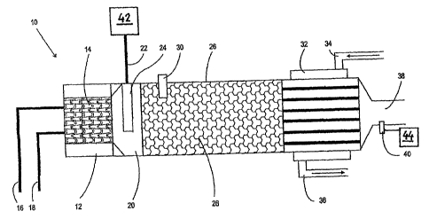
tailled by way of example with reference to the drawing in which:
FIG. 1: is a diagrammatic cross-sectional view of one embodiment
of the fuel cell stack in accordance with the invention comprising a
burner device in accordance with the invention
Referring now to FIG. 1 there is illustrated a diagrammatic cross-
sectional view of a fuel cell stack comprising a fuel cell module 42
assigned a burner device 10 in accordance with the invention as an
afterburner. Liquid fuel and combustion air are fed via a fuel inlet
line 16 and combustion air inlet line 18 respectively into a burner
device 10 preferably configured as a metallic evaporator element 14,
particularly as a metallic foam. Over the surface area of the evapo-
rator element 14, which may be catalytically coated, the supply of
liquid fuel evaporates and is mixed with the combustion air.
From the evaporation zone the resulting combustion mixture flows
into a mixture zone 20 into which fuel gas is introduced via a fuel
gas inlet line 22 which in this case is the anode exhaust of the
fuel cell module 42. In the mixture zone 20 the fuel gas inlet line
22 has preferably the form of a perforated tube or of a porous body,
particularly a porous ceramic body. This end portion of the fuel gas
inlet line 22 is termed fuel gas distributor 24 in the following.
The fuel gas distributor 24 is enveloped in the stream of the com-
3 5 bustion mixture from the evaporation zone, resulting in an homoge-
CA 02584193 2007-04-13
7
nous blend of fuel gas and combustion mixture, in other words, an
enrichment of the combustion mixture. The (enriched) combustion
mixture then flows into the combustion chamber 26 which in the
embodiment as shown is completely filled by a porous body 28. Pro-
truding into the porous body 28 is an igniter 30 which may be con-
figured as an electrical glow pin, for example. The igniter 30
ignites the (enriched) combustion mixture having entered the porous
body 28, resulting in the formation of a stabilized flame and near
total combustion of the combustion mixture. In the rear portion of
the combustion chamber a heat exchanger 32 is arranged, comprising,
for example, a spiral tube with connections for a thermal fluid
inlet line 34 and a thermal fluid outlet line 36. Thermal fluids as
used in this case may be any of the known fluids such as water,
glycol, thermal oils, etc, whereby, if necessary, gaseous sub-
stances, such as air may serve as the thermal transfer medium.
Connecting the rear portion of the combustion chamber 26 is an
exhaust discharge 38 through which the exhaust gases of the combus-
tion are discharged to the exterior.
In the embodiment as shown there is provided in the region of the
exhaust discharge a lambda sensor 40 with the aid of which the
combustion quality can be determined by sensing certain exhaust
parameters. The parameters sensed by the lambda sensor 40 can be fed
into a controller 44 which tweaks blending of the combustion compo-
nents liquid fuel, combustion air and fuel gas to optimize combus-
tion in the combustion chamber 26.
It is, of course, understood that the particular description and
example embodiment as shown in the drawing merely represent an
illustrative embodiment of the invention which is not at all in-
tended to be restrictive. Changes and modifications will be made by
the person skilled in the art. Thus, for instance, additional or
other sensors than the shown lambda sensor 40 may be used partially-
icular, or even no sensor used at all. Furthermore, the special
CA 02584193 2007-04-13
8
geometrical arrangement of the individual portions of the burner is
not necessarily the same as described in FIG. 1. For cooling the
exhaust gases or for preheating fuel gas, liquid fuel and/or combus-
tion air, the exhaust gas or components thereof may be returned to
envelope the corresponding inlet lines 16, 18, 22, it being just as
possible also to return same to the heat exchanger to improve its
efficiency.
It is understood that the features of the invention as disclosed in
the above description, in the drawing as well as in the claims may
be essential to achieving the invention both singly and in any
combination.
List of Reference Numerals:
10 burner device
12 evaporation zone
14 evaporator element
16 fuel inlet line
18 combustion air inlet line
20 mixing zone
22 fuel gas inlet line
24 fuel gas distributor
26 combustion chamber
28 porous body
igniter
32 heat exchanger
34 thermal fluid inlet line
36 thermal fluid outlet line
30 38 exhaust discharge
lambda sensor
42 fuel cell module
44 controller